 Open Access Article
Preparation of an octahedral PtNi/CNT catalyst and its application in high durability PEMFC cathodes†
Jue Wang,
Bing Li *,
Daijun Yang,
Hong Lv
 and
Cunman Zhang*
School of Automotive Studies & Clean Energy Automotive Engineering Center, Tongji University, 4800 Caoan Road, Shanghai 201804, China. E-mail: zhangcunman@tongji.edu.cn; libing210@tongji.edu.cn
First published on 21st May 2018
Abstract
In order to promote the application of proton exchange membrane fuel cells (PEMFCs) in electric vehicles (EVs), it is important to improve the activity of cathode catalysts and the corrosion resistance of carbon supports under high potentials formed during transient vehicle operating conditions. An octahedral PtNi/CNT catalyst with a well-defined structure and enhanced oxygen reduction reaction (ORR) performance was prepared through a surfactant-assisted solvothermal method. Its mass activity and specific activity reach 5.5 and 8.5 times those of the commercial Pt/C catalyst, respectively, and its stability is also higher after durability testing. In addition, the membrane electrode assembly (MEA) fabricated using the octahedral PtNi/CNT catalyst in a cathode exhibits extremely outstanding durability under high potential, and the attenuations of its maximum power density and cell voltage at 600 mA cm−2 are only 4.8% and 3.6%, respectively, which are far below those of the control prepared with commercial Pt/C. These results demonstrate that carbon materials with a graphite structure exhibit actual application potential in the preparation of octahedral catalysts. These carbon-supported octahedral catalysts are expected to be applied in PEMFC cathodes after the materials and preparation process are further improved.
1. Introduction
Proton exchange membrane fuel cells (PEMFCs) have the advantages of low operation temperature, rapid response, high power density and high energy conversion efficiency, and they are very suitable as vehicular power sources.1,2 However, their application has been restricted by some problems, including a very important one which is the activity and durability of the catalyst.3In PEMFCs, it is necessary to introduce catalysts to reduce the activation energy of the electrode reactions and ensure that the reactions can occur spontaneously. Platinum is usually employed as the active component of catalysts in both cathodes and anodes. Pt has better adsorption and catalytic abilities for anode reactions, and its hydrogen oxidation overpotential is less than 25 mV. Thus the hydrogen oxidation reaction (HOR) can be catalyzed well. However, the kinetics of the oxygen reduction reaction (ORR) is extremely slow, and the cathode overpotential can reach 300 mV under open-circuit conditions,4 so it is crucial to improve the activity of cathode catalysts. In order to enhance ORR activity, alloying and morphology control for nanocrystals are widely employed, and a variety of low platinum catalysts5–7 and shape-selective catalysts8–14 have emerged. With further research, it has been found that PtNi (111) facets have extremely high ORR activity, which is about 10 times that of the Pt (111) facets and approximately 90 times that of the commercial Pt/C catalyst.15,16 Its outstanding ORR activity is mainly attributed to the unique atomic and electronic structure of PtNi (111) facets. On the one hand, the Pt–Pt distance is reduced with the doping of 3d transition metal Ni, which is conducive to the adsorption of oxygen molecules on facets. On the other hand, the d-band structure of Pt on PtNi (111) facets is changed to improve selective adsorption for oxygen molecules because the appropriate d-band center position can promote the adsorption of oxygen molecules and decrease the adsorption of other oxygen species, which will reduce the coverage of impurities on facets and increase the exposure of active sites.17,18 Therefore, research on Pt-based octahedral catalysts with highly active (111) facets as the surface has been paid more attention, and various Pt-based octahedral catalysts have successfully emerged, some of which also show outstanding ORR performance compared with commercial Pt/C.19–23 However, this research was confined to the half cell performance of Pt-based octahedral catalysts, and there are few reports on their actual application in single cells.
Among the factors that affect the durability of catalysts, the corrosion of the carbon supports can not be ignored. Under vehicle operating conditions, the high potential resulting from the hydrogen/air interface formed during transient conditions, for example startup/shutdown, will easily cause carbon corrosion in cathodes.24 This carbon corrosion can result in decreases in the number and volume of the supports and the agglomeration of the nanocrystals, and the catalytic activity is then reduced. Moreover, oxygen containing functional groups appearing on the surface of the supports due to carbon oxidation will reduce the conductivity of the catalysts, which will cause the catalyst particles to easily sinter.25–28 These oxygen containing functional groups will also increase the hydrophilicity of the supports and affect gas permeability29 and drainage performance. In addition, carbon corrosion also reduces the thickness of catalyst layers and increases contact resistance, and thus affects the performance of fuel cells.30 To solve the problem of carbon corrosion, there is a more direct and effective way to improve support materials besides optimizing the system control strategy. Research demonstrates that the oxidation of carbon supports usually begins with defect sites on the carbon surface, while the graphite structure is helpful in avoiding defects and exhibits better thermal stability and electrochemical stability.31 Thus, carbon materials with a graphite structure can play an important role in enhancing the corrosion resistance of carbon supports.28,32,33 Vulcan XC-72 carbon black is the most commonly used support material, but its chemical and electrochemical stability need to be improved.31 Carbon nanotubes (CNTs) can be regarded as seamless and hollow tubes made of graphene sheets, and their graphite structure can effectively prevent support corrosion.
In order to make up for the deficiency of research on the durability and single cell performance of Pt-based octahedral catalysts, in this work, an octahedral PtNi catalyst was prepared with CNTs as a support using a facile surfactant-assisted solvothermal method, and the high potential durability of the membrane electrode assembly (MEA) fabricated using this catalyst in a cathode was also investigated. The electrochemical test results show that its ORR performance is better than that of the commercial Pt/C catalyst. Its mass activity and specific activity reach 5.5 and 8.5 times those of commercial Pt/C, respectively, and the attenuation of its electrochemical performance after a half cell durability test is also lower. After the high potential durability test, the MEA prepared with octahedral PtNi/CNTs exhibits an extremely high performance retention rate, and the attenuations of its cell voltage under 600 mA cm−2 and maximum power density are only 4.8% and 3.6%, respectively. These results indicate that the Pt-based octahedral catalysts supported on carbon supports with a graphite structure have enhanced ORR activity and high support corrosion resistance, and they are expected to be applied in a PEMFC cathode after further optimization.
2. Experimental section
2.1 Synthesis of the octahedral PtNi/CNT catalyst
A one-step solvothermal method was selected to prepare the octahedral PtNi/CNT catalyst. Platinum acetylacetonate (Pt(acac)2, 4 mM) and nickel acetylacetonate (Ni(acac)2, 10 mM) as precursors, cetyltrimethylammonium bromide (CTAB, 4 mM) as a structure directing agent and CNTs (81.62 mg) were dissolved into dimethylformamide (DMF, 70 mL), a reducing agent and solvent, to form a uniform mixture. This was then placed into a 100 mL Teflon-lined stainless-steel autoclave. After sealing, the autoclave was heated at 160 °C for 12 h, and was then cooled to room temperature. The products were filtrated and washed with ethanol and ultrapure water (18.2 MΩ), then dried at 80 °C for 12 h and collected.2.2 Physical characterization
Transmission electron microscopy (TEM) was carried out at 200 kV using a JEM 2010 EX microscope and TEM images were used to observe the morphology and dispersion of the catalyst. Scanning electron microscopy (SEM) was conducted using a FEI Sirion 200 to observe the structure and size of the CNTs. X-ray diffraction (XRD) was conducted using CuKα radiation at a 2θ range from 20° to 90° at 0.05° s−1 on a Philips PW 3040/60 powder diffractometer, and XRD data were processed using Jade 6 software. The crystal sizes and lattice parameters of the nanocrystals were calculated according to the Scherrer equation and Bragg’s law. Inductively coupled plasma mass spectrometry (ICP-MS) was employed to obtain the bulk composition of the catalyst.2.3 Electrochemical evaluation
The catalyst was dispersed into a Nafion/methanol solution (mass ratio of 1![[thin space (1/6-em)]](https://www.rsc.org/images/entities/char_2009.gif) :
:![[thin space (1/6-em)]](https://www.rsc.org/images/entities/char_2009.gif) 30) to obtain ink with a catalyst concentration of 2.0 mg mL−1, and then 10 μL ink was coated onto a glassy carbon (GC) electrode (0.247 cm2) as the working electrode, resulting in a Pt loading of 28 μg cm−2. A rotating disk electrode (RDE) technique and a three electrode system containing the above GC electrode, a platinum wire as the counter electrode and a reversible hydrogen electrode (RHE) as the reference electrode were employed to evaluate the ORR performance of the catalysts. The commercial 40 wt% Pt/C catalyst (Pt/C (JM), Johnson Matthey HiSpec 4000) was employed as the control. Cyclic voltammetry (CV) was carried out by sweeping a potential range from 0.05 to 1.15 V vs. RHE at a scan rate of 50 mV s−1 in N2-saturated 0.1 M HClO4 solution. The electrochemically active surface area (ECSA) was calculated based on the area of the absorption and desorption peaks of hydrogen. Linear sweep voltammetry (LSV) was conducted under the same potential range at a scan rate of 5 mV s−1 at 1600 rpm in O2-saturated 0.1 M HClO4 solution. Mass and specific activities were measured at 0.9 V vs. RHE. Accelerated durability testing (ADT) was performed between 0.6 and 1.1 V vs. RHE at 100 mV s−1 for 2000 cycles, and changes in the ECSA and mass activity before and after testing were used to evaluate the durability of the catalysts.
30) to obtain ink with a catalyst concentration of 2.0 mg mL−1, and then 10 μL ink was coated onto a glassy carbon (GC) electrode (0.247 cm2) as the working electrode, resulting in a Pt loading of 28 μg cm−2. A rotating disk electrode (RDE) technique and a three electrode system containing the above GC electrode, a platinum wire as the counter electrode and a reversible hydrogen electrode (RHE) as the reference electrode were employed to evaluate the ORR performance of the catalysts. The commercial 40 wt% Pt/C catalyst (Pt/C (JM), Johnson Matthey HiSpec 4000) was employed as the control. Cyclic voltammetry (CV) was carried out by sweeping a potential range from 0.05 to 1.15 V vs. RHE at a scan rate of 50 mV s−1 in N2-saturated 0.1 M HClO4 solution. The electrochemically active surface area (ECSA) was calculated based on the area of the absorption and desorption peaks of hydrogen. Linear sweep voltammetry (LSV) was conducted under the same potential range at a scan rate of 5 mV s−1 at 1600 rpm in O2-saturated 0.1 M HClO4 solution. Mass and specific activities were measured at 0.9 V vs. RHE. Accelerated durability testing (ADT) was performed between 0.6 and 1.1 V vs. RHE at 100 mV s−1 for 2000 cycles, and changes in the ECSA and mass activity before and after testing were used to evaluate the durability of the catalysts.
2.4 Fabrication, characterization and high potential durability testing of the MEA
The catalyst slurry was prepared by mixing catalyst, 5 wt% Nafion® solution (the mass ratio of the catalyst and Nafion was 3![[thin space (1/6-em)]](https://www.rsc.org/images/entities/char_2009.gif) :
:![[thin space (1/6-em)]](https://www.rsc.org/images/entities/char_2009.gif) 1), ultrapure water and isopropanol under ultrasonication and stirring for 1 h, and the mixture was then sprayed onto a membrane (GORE®, 50 × 50 mm) and dried. The MEA was obtained by fixing a pair of gas diffusion layers (GDLs) (SGL 28BC) onto the as-prepared membrane. In order to evaluate the single cell performance of the as-prepared octahedral PtNi/CNT catalyst, a MEA was fabricated using the octahedral PtNi/CNT catalyst in the cathode and 40 wt% Pt/C (JM) in the anode with Pt loadings of 0.4 mgPt cm−2 and 0.2 mgPt cm−2 for the cathode and anode, respectively. For comparison, a control was also fabricated using Pt/C (JM) for both electrodes with the same Pt loadings as the above MEA. The same single cell tests were performed for both MEAs as follows. The polarization curves were obtained under the operating conditions of a cell temperature of 80 °C, relative humidity (RH) of 80%, inlet gas pressure of 120 kPa and H2/air stoichiometric ratio of 1.7/3.0 on a Greenlight fuel cell testing system. Electrochemical impedance spectroscopy (EIS) was conducted at 80 °C and a RH of 80% under 0.8 V vs. RHE at a frequency range from 1000 Hz to 0.1 Hz. In situ CV curves were measured at 80 °C and a RH of 100% between 0.05 and 1.15 V vs. RHE at 20 mV s−1 with the cathode and anode supplied with N2 and H2 at 200 mL min−1, respectively. In the high potential durability test, under a cell temperature of 80 °C and a RH of 100%, MEAs were kept under a constant voltage of 1.5 V vs. RHE for 1 h with N2 and H2 at 200 mL min−1 supplied to the cathode and anode, respectively. After the high potential durability test, polarization curves, EIS and in situ CV curves were also obtained under the above single cell operating conditions.
1), ultrapure water and isopropanol under ultrasonication and stirring for 1 h, and the mixture was then sprayed onto a membrane (GORE®, 50 × 50 mm) and dried. The MEA was obtained by fixing a pair of gas diffusion layers (GDLs) (SGL 28BC) onto the as-prepared membrane. In order to evaluate the single cell performance of the as-prepared octahedral PtNi/CNT catalyst, a MEA was fabricated using the octahedral PtNi/CNT catalyst in the cathode and 40 wt% Pt/C (JM) in the anode with Pt loadings of 0.4 mgPt cm−2 and 0.2 mgPt cm−2 for the cathode and anode, respectively. For comparison, a control was also fabricated using Pt/C (JM) for both electrodes with the same Pt loadings as the above MEA. The same single cell tests were performed for both MEAs as follows. The polarization curves were obtained under the operating conditions of a cell temperature of 80 °C, relative humidity (RH) of 80%, inlet gas pressure of 120 kPa and H2/air stoichiometric ratio of 1.7/3.0 on a Greenlight fuel cell testing system. Electrochemical impedance spectroscopy (EIS) was conducted at 80 °C and a RH of 80% under 0.8 V vs. RHE at a frequency range from 1000 Hz to 0.1 Hz. In situ CV curves were measured at 80 °C and a RH of 100% between 0.05 and 1.15 V vs. RHE at 20 mV s−1 with the cathode and anode supplied with N2 and H2 at 200 mL min−1, respectively. In the high potential durability test, under a cell temperature of 80 °C and a RH of 100%, MEAs were kept under a constant voltage of 1.5 V vs. RHE for 1 h with N2 and H2 at 200 mL min−1 supplied to the cathode and anode, respectively. After the high potential durability test, polarization curves, EIS and in situ CV curves were also obtained under the above single cell operating conditions.
3. Results and discussion
3.1 Morphology and composition of the octahedral PtNi/CNT catalyst
The TEM images shown in Fig. 1a and b demonstrate that the octahedral nanocrystals were successfully prepared, and the as-prepared nanocrystals are dispersed well on the CNTs with diameters of around 15–20 nm as shown in Fig. 1d. The histogram of the particle size distribution of the octahedral PtNi/CNT catalyst inset in Fig. 1a shows that the average particle size is about 12.8 nm. The high resolution transmission electron microscopy (HRTEM) image in Fig. 1c shows a well-defined octahedral nanocrystal with (111) facets at the surface, and its (111) facet spacing is 2.15 Å, which is smaller than that of pure Pt due to the doping of Ni which has a smaller atomic radius. We suggest that the octahedral morphology of the nanocrystals is attributed to the specific adsorption of CTAB on PtNi (111) facets which decreases its surface energy and slows facet growth, and thus it is beneficial to the exposure of (111) facets.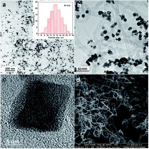 | ||
| Fig. 1 (a and b) TEM images of the octahedral PtNi/CNT catalyst. (c) HRTEM image of an individual PtNi octahedral nanocrystal. (d) SEM image of CNTs. | ||
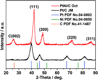
XRD patterns of the octahedral PtNi/CNT catalyst and Pt/C (JM) are exhibited in Fig. 2. In the XRD pattern of the octahedral PtNi/CNT catalyst, the peak located at 25.7° is the graphite (002) peak of CNTs, and the diffraction peaks located at 42.0°, 48.7°, 71.7°, and 86.4° can be assigned to the (111), (200), (220) and (311) facets, respectively, indicating that the octahedral PtNi nanocrystals have a face centered cubic (fcc) structure. In addition, no diffraction peaks of pure Ni or oxide species can be observed, and the diffraction peaks of the octahedral nanocrystals shift to higher 2θ angles than the corresponding peaks of pure Pt, and appear between those of pure Pt and pure Ni, demonstrating that a PtNi alloy state is formed. Due to its smaller full width at half-maximum (FWHM) and higher 2θ angle, the octahedral nanocrystal shows a greater crystal size and smaller lattice parameter as listed in Table S1,† which conforms with the above TEM images.
The composition of the octahedral PtNi/CNT catalyst measured using ICP is 30.17 wt% Pt and 9.31 wt% Ni, respectively, that is, the atom ratio of Pt and Ni is nearly 1![[thin space (1/6-em)]](https://www.rsc.org/images/entities/char_2009.gif) :
:![[thin space (1/6-em)]](https://www.rsc.org/images/entities/char_2009.gif) 1. In this paper, calculations of element content are carried out according to this ratio.
1. In this paper, calculations of element content are carried out according to this ratio.
3.2 ORR activity and durability of the octahedral PtNi/CNT catalyst
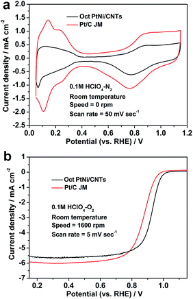
Fig. 3 shows the CV and LSV curves of the octahedral PtNi/CNT catalyst and Pt/C (JM), and their ORR activity parameters at 0.9 V vs. RHE are shown in Table 1. In Fig. 3a, hydrogen adsorption/desorption peaks appear in the region from 0.05 to 0.35 V, and oxygen adsorption/desorption peaks appear in the region from 0.6 to 1.15 V. The peak areas of Pt/C (JM) are obviously larger than those of the octahedral PtNi/CNT catalyst, which may be caused by a great difference in their crystal sizes, in accordance with TEM and XRD results. The LSV curve of the octahedral PtNi/CNT catalyst in Fig. 3b exhibits a higher half-wave potential, signifying enhanced ORR activity. Its mass activity and specific activity at 0.9 V vs. RHE are approximately 5.5 and 8.5 times those of Pt/C (JM), respectively. Reducing the theoretical Pt usage of 82.1% in a cathode can be achieved by obtaining higher mass activity, which is conducive to reducing cost. We suggest its enhanced ORR activity is mainly due to PtNi alloying and its well-defined octahedral morphology. Through forming an alloy with Ni, the Pt–Pt atomic distance can be reduced and the d-band structure is also changed, which makes it more suitable for oxygen selective adsorption.16,34–40 The surface of the as-prepared octahedral nanocrystal is composed of PtNi (111) facets with extremely high ORR activity, and more active sites can be supplied.15,16 Therefore, enhanced mass activity can be realized though the octahedral PtNi/CNT catalyst exhibits a lower ECSA.| Catalyst | ECSA (m2 gPt−1) | Mass activity (mA mgPt−1) | Specific activity (μA cmPt−2) |
|---|---|---|---|
| Oct PtNi/CNTs | 34.8 | 479.0 | 1376.4 |
| Pt/C (JM) | 53.2 | 86.4 | 162.4 |
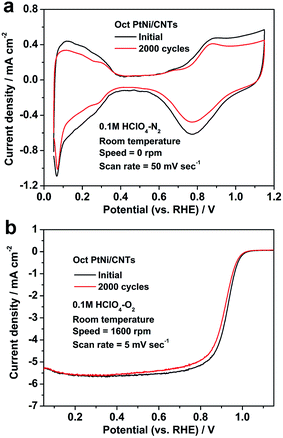
In order to investigate the durability of the octahedral PtNi/CNT catalyst in an electrochemical environment, ADT was performed, and the CV and LSV curves of the octahedral PtNi/CNT catalyst and Pt/C (JM), before and after ADT, are presented in Fig. 4 and Fig. S1,† and bar charts in Fig. S2† show the changes in their ECSAs and mass activities at 0.9 V vs. RHE. After the durability test of 2000 cycles, the ECSA, mass activity and specific activity of Pt/C (JM) are reduced by 38.9%, 64.6% and 42.0%, respectively, whereas the attenuation rates of these parameters for the octahedral PtNi/CNT catalyst are only 27.9%, 33.6% and 8.0%, respectively. In particular, its remaining mass activity is 10.4 times higher than the corresponding remaining mass activity of Pt/C (JM), and even reaches 3.7 times the initial one of Pt/C (JM). The ADT results demonstrate that the octahedral PtNi/CNT catalyst shows improved half cell durability compared with Pt/C (JM). Fig. S3† shows TEM images of Pt/C (JM) before and after ADT. The growth and agglomeration of the nanocrystals can be obviously observed. We infer that the better retention of ORR performance of the octahedral PtNi/CNT catalyst may be ascribed to the stability of its size and morphology due to the larger crystal size of the octahedral nanocrystals and better corrosion resistance of the CNTs. However, the durability of the octahedral PtNi/CNT catalyst still needs to be further improved. The TEM image in Fig. S4† exhibits the nanocrystal after ADT. Its crystal size is not significantly increased, but its morphology becomes smooth. Therefore, we suggest that the decrease in its activity is mainly due to changes in morphology and loss of PtNi (111) facets caused by Ni atoms dissolving and leaching out of the alloy under acidic conditions,21 and thus its durability could be improved by surface modification or doping with stable metal elements, such as Au, Mo and so on.
3.3 Single cell performance and high potential durability of the octahedral PtNi/CNT catalyst
To evaluate the single cell performance of the octahedral PtNi/CNT catalyst, the MEA fabricated using the as-prepared octahedral catalyst in the cathode was tested under the operating conditions described in Section 2.4, and the results are shown in Fig. 5. Its maximum power density and cell voltage at a current density of 600 mA cm−2 are 432.6 mW cm−2 and 0.643 V, respectively. According to Fig. S5,† its maximum power density, calculated using the total Pt loading in both electrodes, is 0.721 kW gPt−1, and thus the Pt loading calculated based on unit power is 1.39 gPt kW−1. The ECSA in a single cell calculated through the in situ CV curve of the octahedral PtNi/CNT catalyst shown in Fig. 6 is 25.7 m2 gPt−1, which is reduced by almost 26.1% compared with the result from the RDE test. The cathode charge transfer resistance obtained from the diameter of the semicircle between high frequency and low frequency41 in the EIS results shown in Fig. 7 is also high. Although the octahedral PtNi/CNT catalyst shows better ORR activity, its single cell performance is unsatisfactory compared with the MEA fabricated using Pt/C (JM). The performance curves are presented in Fig. S6.† As a control, the ECSA of a single cell is 50.9 m2 gPt−1, which is about 5% less than that obtained in the RDE test, revealing very high Pt utilization in the MEA. From the above results, a greatly decreased ECSA indicates that the utilization rate of the octahedral PtNi/CNT catalyst in the single cell is lower. In half cell tests, sufficient contact between the catalyst and the electrolyte can be realized due to the extremely thin catalyst layer on the working electrode, so the catalyst utilization rate is high. However, in the single cell, the electrode reactions occur on the active sites named the “three phase boundary” (TPB), where electrons, protons and gas can simultaneously come into contact with active components. In order to ensure that protons can be successfully transferred to reaction sites, ionomers that fully come into contact with the active components play an important role. In the dispersing process of catalyst slurry, CNTs easily intertwine, which will hinder the contact between ionomers and active components, and reduce the effective utilization of the catalyst. Therefore, the as-fabricated MEA shows unsatisfactory power generation performance. This may need to be solved by optimizing the support and improving the MEA preparation process.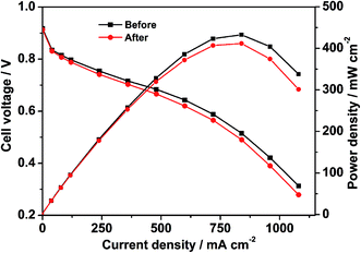 | ||
| Fig. 5 The polarization curves of the MEA, fabricated using the octahedral PtNi/CNT catalyst in the cathode, measured by the area of the MEA before and after a high potential durability test. | ||
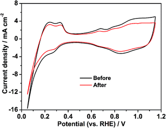 | ||
| Fig. 6 The in situ CV curves of the MEA fabricated using the octahedral PtNi/CNT catalyst in the cathode before and after a high potential durability test. | ||
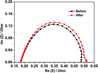 | ||
| Fig. 7 The EIS results of the MEA fabricated using the octahedral PtNi/CNT catalyst in the cathode before and after a high potential durability test. | ||
As presented in Fig. S6,† the control fabricated using Pt/C (JM) exhibits an extremely great attenuation after the high potential durability test, and its maximum power density, cell voltage at 600 mA cm−2 and ECSA are reduced by 33.6%, 16.7% and 80.9%, respectively. Because Pt is passivated at about 1.2 V, the dissolution of Pt can be ignored at the high potential of 1.5 V. In addition, oxidized Pt will be reduced in the CV test, which is not enough to cause a large drop in the ECSA. Therefore, we conclude that the shedding and loss of Pt resulting from the corrosion of the carbon support is the main reason for the decline of single cell performance according to a serious loss in the ECSA.42,43 The red and black lines shown in Fig. 5–7 exhibit comparisons of the polarization curves, in situ CV curves and EIS results of a MEA fabricated using the octahedral PtNi/CNT catalyst in the cathode before and after a high potential durability test, and their performance parameters are listed in Table 2. Under the same testing conditions as the control, the maximum power density, cell voltage at 600 mA cm−2 and ECSA in a single cell are decreased by only 4.8%, 3.6% and 12.8%, respectively, and the cathode charge transfer resistance is also only slightly increased. These results demonstrate that the as-prepared octahedral PtNi/CNT catalyst has extremely outstanding high potential durability in a single cell. We think that the excellent corrosion resistance of CNTs with a graphite structure plays a critical role in inhibiting the oxidation of the carbon support under high potential and maintaining the original structure and properties of the catalyst layer.31–33 Accordingly, though the single cell performance still needs to be improved as a result of the selected support and preparation technique, we believe that this supported octahedral PtNi catalyst has a certain application value under high potential, if the graphitization of well-dispersed carbon supports and making full use of the active components can be achieved.
| Catalyst | Maximum power density (mW cm−2) | Cell voltage@600 mA cm−2 (V) | ECSA (m2 gPt−1) |
|---|---|---|---|
| Before | 432.6 | 0.643 | 25.7 |
| After | 411.6 | 0.620 | 22.4 |
4. Conclusion
In summary, the octahedral PtNi/CNT catalyst was successfully synthesized using a facile surfactant-assisted solvothermal process. In a RDE test, it exhibited better ORR activity and durability. Its mass activity and specific activity at 0.9 V vs. RHE are 5.5 and 8.5 times those of the commercial Pt/C, respectively, and the retention rate of its ORR performance is also higher after ADT. In addition, the MEA fabricated using the octahedral PtNi/CNT catalyst in the cathode demonstrates extremely high performance retention rates after a high potential durability test, and the attenuations of both the maximum power density and cell voltage at 600 mA cm−2 are less than 5%. Although there is potential to increase the single cell performance of the octahedral PtNi/CNT catalyst, our research still proves that carbon materials with a graphite structure as supports have application potential in preparing octahedral catalysts. After further improving the materials and preparation process, we insist that carbon-supported Pt-based octahedral catalysts with prominent high potential durability should be expected to be applied in PEMFC cathodes.Conflicts of interest
There are no conflicts to declare.Acknowledgements
The authors thank the National Natural Science Foundation (No. 21676204).Notes and references
- M. Ball and M. Wietschel, Int. J. Hydrogen Energy, 2009, 34, 615–627 CrossRef.
- B. Hum and X. G. Li, Two-dimensional analysis of PEM fuel cells, J. Appl. Electrochem., 2004, 34, 205–215 CrossRef.
- J. Larminie and A. Dicks, Fuel Cell Systems Explained, 2nd edn, UK, 2003 Search PubMed.
- J. K. Norskv, J. Rossmeisl and A. Logadottir, J. Phys. Chem. B, 2004, 108, 17886–17892 CrossRef.
- H. Y. Zhang, R. Lin, C. H. Cao, J. Zhao and J. X. Ma, Electrochim. Acta, 2011, 56, 7622–7627 CrossRef.
- Z. M. Peng and H. Yang, Nano Today, 2009, 4, 143–164 CrossRef.
- R. F. Wang, S. J. Liao, H. Y. Liu and H. Meng, J. Power Sources, 2007, 171, 471–476 CrossRef.
- N. Toshima, R. Ito, T. Matsushita and Y. Shiraishi, Catal. Today, 2007, 122, 239–244 CrossRef.
- Y. J. Kang, J. Snyder, M. F. Chi, D. G. Li, K. L. More, N. M. Markovic and V. R. Stamenkovic, Nano Lett., 2014, 14, 6361–6367 CrossRef PubMed.
- X. L. Sun, D. G. Li, Y. Ding, W. L. Zhu, S. J. Guo, Z. L. Wang and S. H. Sun, J. Am. Chem. Soc., 2014, 136, 5745–5749 CrossRef PubMed.
- W. Shimizu, K. Okada, Y. Fujita, S. S. Zhao and Y. Murakami, J. Power Sources, 2012, 205, 24–31 CrossRef.
- S. J. Guo, D. G. Li, H. Y. Zhu, S. Zhang, N. M. Markovic, V. R. Stamenkovic and S. H. Sun, Angew. Chem., Int. Ed., 2013, 52, 3465–3468 CrossRef PubMed.
- M. Górzny, A. S. Walton and S. D. Evans, Adv. Funct. Mater., 2010, 20, 1295–1300 CrossRef.
- L. Gancs, T. Kobayashi, M. K. Debe, R. Atanasoski and A. Wieckowski, Chem. Mater., 2008, 20, 2444–2454 CrossRef.
- V. R. Stamenkovic, B. Fowler and B. S. Mun, Science, 2007, 315, 493–497 CrossRef PubMed.
- V. R. Stamenkovic, B. S. Mun, M. Arenz, K. J. J. Mayrhofer, C. A. Lucas, G. F. Wang, P. N. Ross and N. M. Marković, Nat. Mater., 2007, 6, 241 CrossRef PubMed.
- N. Jung, D. Y. Chung, J. Ryua, S. J. Yoo and Y. E. Sun, Nano Today, 2014, 9, 433–456 CrossRef.
- J. Wang, B. Li, T. Yersak, D. J. Yang, Q. F. Xiao, J. L. Zhang and C. M. Zhang, J. Mater. Chem. A, 2016, 4, 11559–11581 Search PubMed.
- S. Ryogo, O. Kaoru, F. Terumi and I. Masao, J. Power Sources, 2014, 269, 117–123 CrossRef.
- C. H. Cui, L. Gan, H. H. Li, S. H. Yu, M. Heggen and P. Strasser, Nano Lett., 2012, 12, 5885 CrossRef PubMed.
- C. H. Cui, L. Gan, M. Heggen, S. Rudi and P. Strasser, Nat. Mater., 2013, 12, 765–771 CrossRef PubMed.
- X. Q. Huang, Z. P. Zhao, Y. Chen, E. B. Zhu, M. F. Li, X. F. Duan and Y. Huang, Energy Environ. Sci., 2014, 7, 2957–2962 Search PubMed.
- X. Q. Huang, Z. P. Zhao, L. Cao, Y. Chen, E. B. Zhu, Z. Y. Lin, M. F. Li, A. M. Yan, A. Zettl, M. Y. Wang, X. F. Duan, T. Mueller and Y. Huang, Science, 2015, 348, 1230–1234 CrossRef PubMed.
- S. Maass, F. Finsterwalder and G. Frank, J. Power Sources, 2008, 176, 444–451 CrossRef.
- Y. Shao, G. Yin and Y. Gao, J. Power Sources, 2007, 171, 558–566 CrossRef.
- K. H. Kangasniemi, D. A. Condit and T. D. Jarvi, J. Electrochem. Soc., 2004, 151, E125–E132 CrossRef.
- M. Cai, M. S. Ruthkosky and B. Merzougui, J. Power Sources, 2006, 160, 977–986 CrossRef.
- F. Coloma, A. Sepulvedaescribano and F. Rodriguezreinoso, J. Catal., 1995, 154, 299–305 CrossRef.
- Z. Siroma, N. Fujiwara and T. Ioroi, J. Power Sources, 2004, 126, 41–45 CrossRef.
- E. Guilminot, A. Corcella and F. Charlot, J. Electrochem. Soc., 2007, 154, B96–B105 CrossRef.
- D. Stevens, M. Hicks and G. Haugen, J. Electrochem. Soc., 2005, 152, A2309–A2315 CrossRef.
- B. Eastwood, P. Christensen and R. Armstrong, J. Solid State Electrochem., 1999, 3, 179–186 CrossRef.
- Y. Shao, G. Yin and J. Zhang, Electrochim. Acta, 2006, 51, 5853–5857 CrossRef.
- I. E. L. Stephens, A. S. Bondarenko, U. Grønbjerg, J. Rossmeisl and I. Chorkendorff, Energy Environ. Sci., 2012, 5, 6744–6762 Search PubMed.
- C. Wang, M. Chi, G. Wang, D. Vliet, D. Li, K. More, H. H. Wang, J. A. Schlueter, N. M. Markovic and V. R. Stamenkovic, Adv. Funct. Mater., 2011, 21, 147 CrossRef.
- Y. Bing, H. Liu, L. Zhang, D. Ghosh and J. Zhang, Chem. Soc. Rev., 2010, 39, 2184 RSC.
- P. Liu and J. K. Nørskov, Phys. Chem. Chem. Phys., 2001, 3, 3814–3818 RSC.
- J. R. Kitchin, J. K. Nørskov, M. A. Barteau and J. G. Chen, J. Chem. Phys., 2004, 120, 10240–10246 CrossRef PubMed.
- N. M. Marković, H. A. Gasteiger, B. N. Grgur and P. N. Ross, J. Electroanal. Chem., 1999, 467, 157–163 CrossRef.
- B. Hammer and J. K. Nørskov, Adv. Catal., 2000, 45, 71–129 Search PubMed.
- B. Li, R. Lin, D. J. Yang and J. X. Ma, Int. J. Hydrogen Energy, 2010, 35, 2814–2819 CrossRef.
- T. A. Bekkedahl, L. J. Bregoli, R. D. Breault, E. A. Dykeman, J. P. Meyers, T. W. Patterson, T. Skiba, C. Vargas, D. Yang and J. S. Yi, US pat., 6 913 845, 2005.
- C. R. Reiser, L. Bregoli, T. W. Patterson, J. S. Yi, J. D. Yang, M. L. Perry and T. D. Jarvi, Electrochem. Solid-State Lett., 2005, 8, A273 CrossRef.
Footnote |
| † Electronic supplementary information (ESI) available. See DOI: 10.1039/c8ra02158a |
| This journal is © The Royal Society of Chemistry 2018 |

