 Open Access Article
A hybrid electric field assisted vacuum membrane distillation method to mitigate membrane fouling
Qinglin Huang *abc,
Huan Liuab,
Yafeng Wangb and
Changfa Xiaoac
aState Key Laboratory of Separation Membranes and Membrane Process, Tianjin Polytechnic University, 399 West Binshui Road, Xiqing District, Tianjin, 300387, P. R. China. E-mail: huangqinglin@tjpu.edu.cn; Tel: +86-22-83955795
bDepartment of Material Science and Engineering, Tianjin Polytechnic University, Tianjin 300387, P. R. China
cNational Center for International Research on Membrane Science and Technology Tianjin Polytechnic University, Tianjin, 300387, P. R. China
First published on 16th May 2018
Abstract
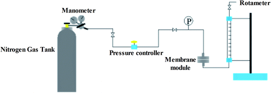
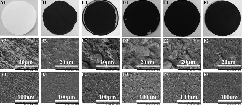
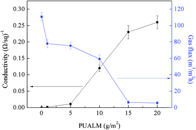
We proposed a novel method for vacuum membrane distillation (VMD) called Electric Field Assisted Vacuum Membrane Distillation (EVMD) that can be used to mitigate membrane fouling. A biaxial stretching polytetrafluoroethylene (PTFE) membrane was utilized as the base membrane, and multi-walled carbon nanotubes (MWCNTs) or a mixture of MWCNTs/graphene as a conductive substrate. During EVMD, the conductive PTFE membrane acted as the cathode while a stainless-steel wire mesh surrounding the conductive membrane acted as the anode. The effect of the per unit area loading mass (PUALM) of the conductive substrate on the membrane performance were investigated. Results revealed that for a PUALM of 10 g m−2, the PTFE membrane not only exhibited excellent conductivity but also showed a high rate of gas flux. Doping graphene into the MWCNT conductive substrate led to the formation of nano-channels which served to improve the membrane distillation flux and the membrane hydrophobicity. The effects of the electric field strength as well as humic acid (HA) concentration on the antifouling performance during EVMD were also investigated. Results showed that during EVMD, the PTFE conductive membrane exhibited the best antifouling ability using an intermittent electric field with a field strength of 1.0 V cm−1.
1. Introduction
Due to a growing scarcity of water resources, improvements in water treatment technologies have become increasingly important.1 Membrane technologies such as microfiltration (MF), ultrafiltration (UF), nanofiltration (NF), and membrane distillation (MD) have increased in popularity due to their low investment costs and high efficiency. In particular, non-isothermal membrane separation technology membrane distillation (MD) is a promising emerging separation and purification technology. In this method, the trans-membrane vapor pressure acts as the driving force2 while a hydrophobic microporous membrane acts as the medium. As a configuration of MD, Vacuum Membrane Distillation (VMD) attracts more attention owing to the vacuum in the permeate side which brings about a higher driving force and further membrane flux.3 Compared with traditional separation technologies, as well as other pressure-driven membrane separation processes, MD has advantages of low energy consumption and nearly 100% rejection,4,5 the ability to condense non-volatile agents while removing volatile organic agents in the water solution,6,7 and so on.8,9However, despite its many attractive advantages, MD has yet to be widely applied.10 The large scale development of membrane separation technologies, such as UF, NF, and MD,4,5,10–19 have been hindered by membrane fouling, a problem which results in a sharp decline in the membrane flux and shortens the membrane's lifespan. Membrane fouling during MD is primarily caused by inorganic scaling, particulate and colloidal fouling, and/or bio-fouling.14 Natural organic matter (NOM), such as humic acid (HA), bovine serum albumin (BSA), and Sodium Alginate (SA), has also been seen to lead to membrane fouling.20 HA in particular has been identified as a principal NOM foulant for membrane processes, leading many researches to focus on HA fouling during MD.4,11,13,21,22 Multiple strategies have been employed in order to inhibit membrane fouling for MD, including pretreatment of the feeding solution, membrane flushing, gas bubbling,18 surface modification to create an anti-fouling membrane,23 photo-catalysis24 and so on.12,25 Despite all efforts however, membrane fouling continues to be a challenge for implementation of the technique.26
In recent decades, electro-chemical techniques have been coupled with membrane separation technologies and applied to water treatment of industrial wastewater,27 particularly in the degradation of phenol.28,29 Many studies have shown that use of a Membrane Bioreactor (MBR) coupled with an electric field is able to effectively mitigate membrane fouling.30–32 For example, Raed Hashaikeh used periodic electrolysis to effectively clean membranes,33 Boor Singh Lalia employed electrically conductive membranes able to self-clean any bio-fouling,34 and Li et al.35 introduced an electro-catalytic membrane reactor able to mitigate membrane fouling. More recently, carbon nanotubes and graphene have been used as good conductive materials across many fields.36–41 Use of these materials for water treatment is also developing rapidly.42–45
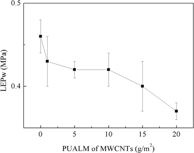
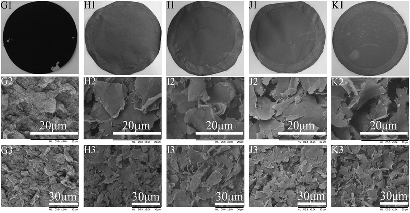
In this article, we propose a novel method of improved, anti-fouling MD called Electric Field Assisted Vacuum Membrane Distillation (EVMD). This method utilizes a biaxial stretching PTFE membrane as a base membrane and multi-walled carbon nanotubes (MWCNTs), or a mixture of MWCNTs/garphenes, as a conductive substrate.33,46,47 The effects of the per unit area loading mass (PUALM) of the MWCNTs on the overall membrane performance were investigated in terms of the surface morphology, gas flux, and conductivity. The effects of the electric field strength and HA concentration on the antifouling performance during EVMD were also investigated.
2. Experimental
2.1. Materials
Biaxial stretching PTFE membranes with an average pore diameter of 0.22 μm were supplied by Haining Nengda Filter Equipment Co., Ltd (Haining, China). Sodium chloride (NaCl, AR grade) was obtained from Tianjin Fengchuan Chemical Reagent Co., Ltd (Tianjin, China). Humic acid (HA, CP) was purchased from Tianjin Guangfu Fine Chemical Research Institute (Tianjin, China). Carboxylated MWCNTs were purchased from Beijing BOYU GAOKE New Material Technology Co., Ltd (Beijin, China). Graphene was obtained from Ximen Knano Graphene Technology Co., LTD (Xiamen, China). N,N-Dimethylacetamide (DMAc, AR grade) was obtained from Tianjin Kemiou Chemical Reagent Co., Ltd (Tianjin, China).2.2. Preparation of a conductive PTFE membrane
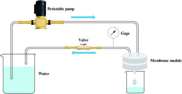
0.01% by wt of MWCNTs, or 0.01% by wt of a mixture of MWCNTs/graphenes, was dispersed in DMAc using an ultrasonic cleaner with the fixing frequency set at 40 kHz for 4 h. Before vacuum filtration, the PTFE was soaked in ethanol in order to clean the membrane surface as well as decrease resistance during the vacuum filtration process. Next, an appropriate amount of the suspension containing the conductive substrate was filtered through the membrane using vacuum filtration at 30 kPa, as showed in Fig. 1. The membrane was then vacuum dried at 0.09 MPa and 60 °C. The effective area of the prepared membrane was 38.48 cm2.2.3. EVMD test
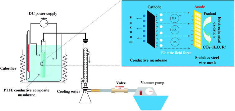
A prepared PTFE conductive membrane (with an effective surface area of 20 cm2) was fixed to a porous tube to create a tubular shaped membrane module. During the EVMD test, an aqueous solution of HA (20 mg L−1) pretreated with an aqueous solution of NaOH (40 g L−1) was used as the pollutant. Additionally, an aqueous solution of NaCl (3.5% by wt) was used as both an electrolyte and an inorganic contaminant. During the EVMD process, the temperature of the feed liquid was kept constant at 70 °C and the vacuum pressure was set at 0.095 MPa. An intermittent electric field with an interval of 0.5 h was applied in order to hopefully mitigate membrane fouling (Fig. 2).2.4. Characterization
2.5. EVMD separation performance
 | (1) |
 | (2) |
3. Results and discussion
3.1. Effects of the PUALM of MWCNTs on membrane performance
3.2. Effects of graphene doped MWCNTs on membrane performance
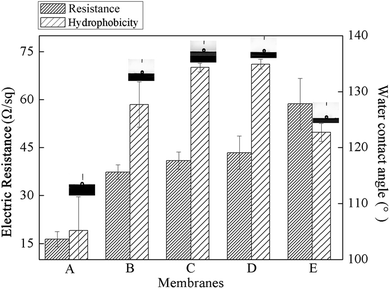
Kunli Goh48 had previously reported the formation of a nanostructure on the membrane that improved the membrane hydrophobicity as well as the distillation flux. In hopes of seeing such benefits and build this nanostructure, a mixture of graphenes and MWCNTs were used as the conductive substrate and the subsequent effects on membrane performance were investigated. The PUALM for all tests was kept at 10 g m−2 in order to maintain the good conductivity and separation performance of the membrane.![[thin space (1/6-em)]](https://www.rsc.org/images/entities/char_2009.gif) :
:![[thin space (1/6-em)]](https://www.rsc.org/images/entities/char_2009.gif) 2 ratio of graphene to MWCNTs showed both good hydrophobicity and conductivity, and they were then applied to EVMD process.
2 ratio of graphene to MWCNTs showed both good hydrophobicity and conductivity, and they were then applied to EVMD process.
3.3. Antifouling performance during EVMD
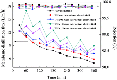
Use of EVMD was observed to obviously mitigate any decline in membrane distillation flux, indicating effective suppression of membrane fouling. As shown in Fig. 10, all rejection values were measured to be above 99.5%. When raw PTFE membranes were used for VMD, the membrane distillation flux declined sharply to 36.38% after only 6 hours operation due to serious membrane fouling. It was also observed that membrane fouling resulted from adhesion of HA to the membrane surface and subsequent blocking of membrane pores, as shown in Fig. 11. Compared with a raw PTFE membrane, the rate of decrease for distillation flux across the membrane was slower using the PTFE conductive microporous membrane to conduct VMD without an intermittent electric field, dropping only to 47.37%. Due to the electronegativity of the carboxylated MWCNTs,49 it was difficult for HA to adhere to the membrane surface. Also, MWCNTs and graphenes both have excellent thermal conductivities and can act to reduce the temperature polarization and thereby further mitigate the decline in membrane distillation flux. The conductive substrate layer can also act as an anti-pollution layer. When an intermittent electric field was applied during the VMD process, the membrane distillation flux was unstable, with volatile ups and downs over time. HA is negatively charged and is strongly electronegative, therefore when the PTFE conductive microporous membrane was employed as the cathode, HA in solution was electrically repulsed from the membrane surface and thereby relieved membrane fouling. Furthermore, due to electrochemical oxidation, HA can be degraded near the anode, resulting in a decline of the HA concentration in the feeding liquid during the EVMD process. Another factor for these results may be the generation of H2O2 in solution which could act to clean the membrane surface at the cathode. The in situ cleaning of the membrane by electrochemically produced H2O2 has been previously reported to decrease potential membrane fouling.50 Furthermore, electrolysis led to the formation of micro-bubbles along the membrane surface, which acted to remove foulants and prevent adsorption of HA onto the membrane surface.34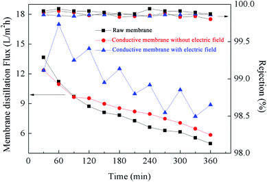 | ||
| Fig. 10 Membrane distillation flux measured using raw PTFE membranes and conductive microporous PTFE membranes with or without an intermittent electric field at 1.0 V cm−1. | ||
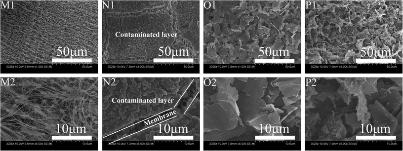 | ||
| Fig. 11 SEM images of raw PTFE membranes before (M) and after (N) VMD tests as well as PTFE conductive microporous membranes before (O) and after (P) EVMD tests. | ||
4. Conclusions
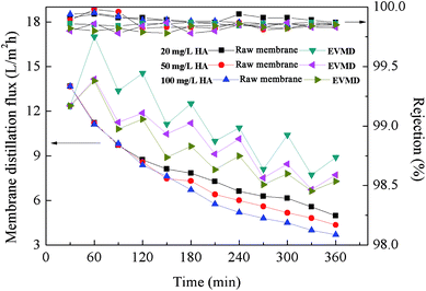
In conclusion, the prepared PTFE conductive microporous membranes possessed excellent conductivity and membranes with a fixed PUALM of 10 g m−2. EVMD was observed to effectively mitigate membrane fouling due to electric field and electrochemical action on the pollutants. It was determined that the best antifouling performance and membrane distillation flux recovery rate was achieved using an intermittent electric field with a field strength of 1.0 V cm−1. Also, it was observed that the antifouling performance of EVMD was weakened with an increase in HA concentration due to the increased likelihood of HA coming into contact with the membrane surface.Conflicts of interest
There are no conflicts to declare.Acknowledgements
This work was supported by the Young Elite Scientists Sponsorship Program by China Association for Science and Technology (No. YESS20160168), Tianjin Municipal University Science and Technology Development Fund Project (No. TJ 20140306), and the Science and Technology Plans of Tianjin (No. 15PTSYJC00240).References
- M. A. Shannon, P. W. Bohn, M. Elimelech, J. G. Georgiadis, B. J. Marinas and A. M. Mayes, Science and technology for water purification in the coming decades, Nature, 2008, 452, 301–310 CrossRef PubMed.
- M. Khayet, Membranes and theoretical modeling of membrane distillation: a review, Adv. Colloid Interface Sci., 2011, 164, 56–88 CrossRef PubMed.
- L. D. Tijing, J.-S. Choi, S. Lee, S.-H. Kim and H. K. Shon, Recent progress of membrane distillation using electrospun nanofibrous membrane, J. Membr. Sci., 2014, 453, 435–462 CrossRef.
- G. Naidu, S. Jeong, S.-J. Kim, I. S. Kim and S. Vigneswaran, Organic fouling behavior in direct contact membrane distillation, Desalination, 2014, 347, 230–239 CrossRef.
- L. D. Tijing, Y. C. Woo, J.-S. Choi, S. Lee, S.-H. Kim and H. K. Shon, Fouling and its control in membrane distillation—A review, J. Membr. Sci., 2015, 475, 215–244 CrossRef.
- E. Drioli, A. Ali and F. Macedonio, Membrane distillation: Recent developments and perspectives, Desalination, 2015, 356, 56–84 CrossRef.
- F. Shao, C. Hao, L. Ni, Y. Zhang, R. Du, J. Meng, Z. Liu and C. Xiao, Experimental and theoretical research on N-methyl-2-pyrrolidone concentration by vacuum membrane distillation using polypropylene hollow fiber membrane, J. Membr. Sci., 2014, 452, 157–164 CrossRef.
- A. Criscuoli, P. Bafaro and E. Drioli, Vacuum membrane distillation for purifying waters containing arsenic, Desalination, 2013, 323, 17–21 CrossRef.
- J. Chen, Y. Zhang, Y. Wang, X. Ji, L. Zhang, X. Mi and H. Huang, Removal of inhibitors from lignocellulosic hydrolyzates by vacuum membrane distillation, Bioresour. Technol., 2013, 144, 680–683 CrossRef PubMed.
- X. Lu, Y. Peng, L. Ge, R. Lin, Z. Zhu and S. Liu, Amphiphobic PVDF composite membranes for anti-fouling direct contact membrane distillation, J. Membr. Sci., 2016, 505, 61–69 CrossRef.
- S. Srisurichan, R. Jiraratananon and A. G. Fane, Humic acid fouling in the membrane distillation process, Desalination, 2005, 174, 63–72 CrossRef.
- D. Hou, L. Zhang, Z. Wang, H. Fan, J. Wang and H. Huang, Humic acid fouling mitigation by ultrasonic irradiation in membrane distillation process, Sep. Purif. Technol., 2015, 154, 328–337 CrossRef.
- Y. Z. Tan, J. W. Chew and W. B. Krantz, Effect of humic-acid fouling on membrane distillation, J. Membr. Sci., 2016, 504, 263–273 CrossRef.
- D. M. Warsinger, J. Swaminathan, E. Guillen-Burrieza, H. A. Arafat and J. H. Lienhard V, Scaling and fouling in membrane distillation for desalination applications: A review, Desalination, 2015, 356, 294–313 CrossRef.
- A. Kayvani Fard, T. Rhadfi, M. Khraisheh, M. A. Atieh, M. Khraisheh and N. Hilal, Reducing flux decline and fouling of direct contact membrane distillation by utilizing thermal brine from MSF desalination plant, Desalination, 2016, 379, 172–181 CrossRef.
- A. Zarebska, D. R. Nieto, K. V. Christensen and B. Norddahl, Ammonia recovery from agricultural wastes by membrane distillation: Fouling characterization and mechanism, Water Res., 2014, 56, 1–10 CrossRef PubMed.
- M. Gryta, Fouling in direct contact membrane distillation process, J. Membr. Sci., 2008, 325, 383–394 CrossRef.
- Z. Ding, L. Liu, Z. Liu and R. Ma, The use of intermittent gas bubbling to control membrane fouling in concentrating TCM extract by membrane distillation, J. Membr. Sci., 2011, 372, 172–181 CrossRef.
- J. W. Chew, W. B. Krantz and A. G. Fane, Effect of a macromolecular- or bio-fouling layer on membrane distillation, J. Membr. Sci., 2014, 456, 66–76 CrossRef.
- Y. Hao, A. Moriya, T. Maruyama, Y. Ohmukai and H. Matsuyama, Effect of metal ions on humic acid fouling of hollow fiber ultrafiltration membrane, J. Membr. Sci., 2011, 376, 247–253 CrossRef.
- J. I. M. M. Khayet, Effect of salt concentration during the treatment of humic acid solutions by membrane distillation, Desalination, 2004, 168, 9 Search PubMed.
- G. Naidu, S. Jeong and S. Vigneswaran, Interaction of humic substances on fouling in membrane distillation for seawater desalination, Chem. Eng. J., 2015, 262, 946–957 CrossRef.
- J. R. Du, S. Peldszus, P. M. Huck and X. Feng, Modification of membrane surfaces via microswelling for fouling control in drinking water treatment, J. Membr. Sci., 2015, 475, 488–495 CrossRef.
- J. Grzechulska-Damszel, S. Mozia and A. W. Morawski, Integration of photocatalysis with membrane processes for purification of water contaminated with organic dyes, Catal. Today, 2010, 156, 295–300 CrossRef.
- D. Hou, G. Dai, H. Fan, H. Huang and J. Wang, An ultrasonic assisted direct contact membrane distillation hybrid process for desalination, J. Membr. Sci., 2015, 476, 59–67 CrossRef.
- Y. Yang, J. Li, H. Wang, X. Song, T. Wang, B. He, X. Liang and H. H. Ngo, An Electrocatalytic Membrane Reactor with Self-Cleaning Function for Industrial Wastewater Treatment, Angew. Chem., Int. Ed., 2011, 50, 2148–2150 CrossRef PubMed.
- D. Rajkumar and K. Palanivelu, Electrochemical treatment of industrial wastewater, J. Hazard. Mater., 2004, 113, 123–129 CrossRef PubMed.
- Y. J. Feng and X. Y. Li, Electro-catalytic oxidation of phenol on several metal-oxide electrodes in aqueous solution, Water Res., 2003, 37, 2399–2407 CrossRef PubMed.
- Y. Q. Wang, B. Gu and W. L. Xu, Electro-catalytic degradation of phenol on several metal-oxide anodes, J. Hazard. Mater., 2009, 162, 1159–1164 CrossRef PubMed.
- L. Liu, F. Zhao, J. Liu and F. Yang, Preparation of highly conductive cathodic membrane with graphene (oxide)/PPy and the membrane antifouling property in filtrating yeast suspensions in EMBR, J. Membr. Sci., 2013, 437, 99–107 CrossRef.
- J. Huang, Z. Wang, J. Zhang, X. Zhang, J. Ma and Z. Wu, A novel composite conductive microfiltration membrane and its anti-fouling performance with an external electric field in membrane bioreactors,, Sci. Rep., 2015, 5, 9268 CrossRef PubMed.
- K. Akamatsu, Y. Yoshida, T. Suzaki, Y. Sakai and H. Nagamoto, S.-i. Nakao, Development of a membrane–carbon cloth assembly for submerged membrane bioreactors to apply an intermittent electric field for fouling suppression, Sep. Purif. Technol., 2012, 88, 202–207 CrossRef.
- R. Hashaikeh, B. S. Lalia, V. Kochkodan and N. Hilal, A novel in situ membrane cleaning method using periodic electrolysis, J. Membr. Sci., 2014, 471, 149–154 CrossRef.
- B. S. Lalia, F. E. Ahmed, T. Shah, N. Hilal and R. Hashaikeh, Electrically conductive membranes based on carbon nanostructures for self-cleaning of biofouling, Desalination, 2015, 360, 8–12 CrossRef.
- Y. Yang, J. Li, H. Wang, X. Song, T. Wang, B. He, X. Liang and H. H. Ngo, An electrocatalytic membrane reactor with self-cleaning function for industrial wastewater treatment, Angew. Chem., 2011, 50, 2148–2150 CrossRef PubMed.
- X. Huang, Z. Zeng, Z. Fan, J. Liu and H. Zhang, Graphene-Based Electrodes, Adv. Mater., 2012, 24, 5979–6004 CrossRef PubMed.
- N. O. Weiss, H. Zhou, L. Liao, Y. Liu, S. Jiang, Y. Huang and X. Duan, Graphene: An Emerging Electronic Material, Adv. Mater., 2012, 24, 5782–5825 CrossRef PubMed.
- H. Chen, M. B. Müller, K. J. Gilmore, G. G. Wallace and D. Li, Mechanically Strong, Electrically Conductive, and Biocompatible Graphene Paper, Adv. Mater., 2008, 20, 3557–3561 CrossRef.
- O. C. Compton, D. A. Dikin, K. W. Putz, L. C. Brinson and S. T. Nguyen, Electrically conductive “alkylated” graphene paper via chemical reduction of amine-functionalized graphene oxide paper, Adv. Mater., 2010, 22, 892–896 CrossRef PubMed.
- S. Garaj, W. Hubbard, A. Reina, J. Kong, D. Branton and J. A. Golovchenko, Graphene as a subnanometre trans-electrode membrane, Nature, 2010, 467, 190–193 CrossRef PubMed.
- Z. Q. Tian, S. H. Lim, C. K. Poh, Z. Tang, Z. Xia, Z. Luo, P. K. Shen, D. Chua, Y. P. Feng, Z. Shen and J. Lin, A Highly Order-Structured Membrane Electrode Assembly with Vertically Aligned Carbon Nanotubes for Ultra-Low Pt Loading PEM Fuel Cells,, Adv. Energy Mater., 2011, 1, 1205–1214 CrossRef.
- Y. Han, Z. Xu and C. Gao, Ultrathin Graphene Nanofiltration Membrane for Water Purification, Adv. Funct. Mater., 2013, 23, 3693–3700 CrossRef.
- H. Y. Yang, Z. J. Han, S. F. Yu, K. L. Pey, K. Ostrikov and R. Karnik, Carbon nanotube membranes with ultrahigh specific adsorption capacity for water desalination and purification, Nat. Commun., 2013, 4, 2220 Search PubMed.
- L. Dumée, V. Germain, K. Sears, J. Schütz, N. Finn, M. Duke, S. Cerneaux, D. Cornu and S. Gray, Enhanced durability and hydrophobicity of carbon nanotube bucky paper membranes in membrane distillation, J. Membr. Sci., 2011, 376, 241–246 CrossRef.
- S. Kar, R. C. Bindal and P. K. Tewari, Carbon nanotube membranes for desalination and water purification: Challenges and opportunities, Nano Today, 2012, 7, 385–389 CrossRef.
- D. A. Dikin, S. Stankovich, E. J. Zimney, R. D. Piner, G. H. Dommett, G. Evmenenko, S. T. Nguyen and R. S. Ruoff, Preparation and characterization of graphene oxide paper, Nature, 2007, 448, 457–460 CrossRef PubMed.
- A. S. Brady-Estevez, S. Kang and M. Elimelech, A single-walled-carbon-nanotube filter for removal of viral and bacterial pathogens, Small, 2008, 4, 481–484 CrossRef PubMed.
- W. J. Kunli Goh, H. E. Karahan, S. Zhai, L. Wei, D. Yu, R. Wang, A. G. Fane and Y. Chen, All-Carbon Nanoarchitectures as High-Performance Separation Membranes with Superior Stability, Adv. Funct. Mater., 2015, 25, 12 CrossRef.
- S.-M. Park, J. Jung, S. Lee, Y. Baek, J. Yoon, D. K. Seo and Y. H. Kim, Fouling and rejection behavior of carbon nanotube membranes, Desalination, 2014, 343, 180–186 CrossRef.
- Y. K. Wang, W. W. Li, G. P. Sheng, B. J. Shi and H. Q. Yu, In-situ utilization of generated electricity in an electrochemical membrane bioreactor to mitigate membrane fouling, Water Res., 2013, 47, 5794–5800 CrossRef PubMed.
| This journal is © The Royal Society of Chemistry 2018 |


