 Open Access Article
Influence of offset angle of mid-secondary air nozzles on gas-particle flow characteristics in a furnace
Zhiqiang Wang,
Yingjie Hu ,
Xingxing Cheng
 *,
Ming Liu and
Chunyuan Ma
National Engineering Laboratory for Coal-fired Pollutants Emission Reduction, Shandong University, 17923 Jingshi Road, Jinan 250061, P. R. China. E-mail: xcheng@sdu.edu.cn
First published on 15th May 2018
Abstract
A three-component particle-dynamics anemometer was used to measure the characteristics of two-phase gas-particle flows in a primary air nozzle using a gas/particle two-phase test facility. The jet trajectory of primary air velocities, Reynolds stress and particle concentration profiles were obtained. Based on this, the advantages and disadvantages of increasing the offset angle were analyzed to optimize performance. The results show that gas-particle slippage is not noticeable in the furnace, even though the mid-secondary air offset angle changes. Within the jet's free developing zone, the location of the peak concentration does not change with the mid-secondary air offset angles. Properly enlarging the offset angle of mid-secondary air nozzles will delay the mixing of the secondary air into the primary-air-and-coal mixture and realize horizontal-staged combustion in a furnace. It also can enhance the stability of airflow and form a better blended jet tail, meanwhile reducing the vortex at the back-fire side and avoiding a short circuiting of the airflow. It is favorable for increasing combustion efficiency and preventing slagging and high-temperature corrosion.
1. Introduction
Thermal power plants consume 44.8% of total coal production and generate 75.7% of total electricity in China,1 which is expected to continue for many years to come. Meanwhile, pollutant emission is serious and new pollution control techniques are required. Moreover, the kind of coal for utility boilers varies within a certain range and a lot of low grade coal that features low volatile content and low ash fusion temperature is consumed.2 So it has a tendency of slagging when burning and NOx emission is difficult to control.3,4 One effective way to decrease NOx emission is to raise the pulverized coal concentration in the combustion area.5 However, this could result in slag, high-temperature corrosion and a decrease in combustion efficiency.3,6 Raising the temperature of the combustion area has a favorable effect on combustion efficiency and stability, but it will increase NOx emission and cause high-temperature corrosion. The corrosion mechanisms can be attributed to the attack from sulfur species (H2S and [S]) and chlorine-based species (HCl and Cl2), and to the deposition of unoxidized material (FeS and char).7,8 This is because the pulverized coal-air flow may strike the wall to form a reducing atmosphere near the water-cooled wall.9,10 And it will lead to reducing substances being released from coal. These substances (H2S, [S], HCl and Cl2) will diffuse to and react with the bare tube metal forming FeS, Fe3O4, FeCl2, FeS2, etc.11 Furthermore, a high pulverized coal concentration could be formed near the water-cooled wall. And the ash melting point temperature of that pulverized coal will be much higher than the fireside water-cooled wall temperature because of the endothermic effect of the water-cooled wall,11 so it is more likely to form slagging. Moreover, this process may become more serious in a tangential-fired boiler because the trend of primary air jet deflection occurring more easily.11,12 Therefore, it is significant to develop combustion techniques with combustion stability, slagging resistance, anti-high-temperature corrosion, pollution control and high combustion efficiency.13There are two main firing modes for utility boilers in China: the corner arranged tangential pulverized coal burner and on-wall arranged swirl pulverized coal burner. Based on installed capacity, the corner arranged mode accounts for more than 70% of the total amount. In consideration of this situation, many researchers have done plenty of work on this aspect and have invented various new pulverized coal burners.14–23 Among these technologies, the horizontal bias burner proposed by Qin Yukun and co-workers performs well in engineering applications.4,6,13 The primary air is divided into flow A with high concentration pulverized coal and flow B with low concentration pulverized coal. Flow A injects tangentially at the fire-facing side and flow B at the back side. The combustion of the two flows deviates from stoichiometric ratio and approaches stoichiometric ratio in total, resulting in low NOx emission and high combustion efficiency. At the fire-facing side, pulverized coal can achieve timely ignition and stable combustion. At the back fire side, the ash fusion temperature increases as a result of an oxidizing atmosphere near the water-cooled wall, which is favorable for preventing slagging and high-temperature corrosion.
However, the horizontal bias burner performance is expected to be improved to adapt to low-grade coal and increasingly stringent environmental standards. One of the key factors for research is the offset angle of mid-secondary air nozzles, which has a significant influence on combustion. To date, there are a number of factors that are not well described, such as the influence of offset angle on the jet trajectory of primary air, diameter of tangential circle, slagging, high-temperature corrosion, etc. In this experiment, three-dimensional phase Doppler anemometry (PDA) is used to study the influence of the offset angle of mid-secondary air nozzles on gas-particle flow characteristics for gas/solid two-phase cold test beds. Based on this, the advantages and disadvantages of increasing the offset angle were analyzed to optimize performance.
2. Experimental
A three-dimensional PDA system was used to study the effect of offset angles of mid-secondary air nozzles on the characteristics of gas–solid flows in a furnace. It is virtually impossible to replicate all the physical and chemical processes of a full-sized industrial burner in a scaled-down model used in research, but it would be too expensive to conduct experiments in a full-sized burner. However, results from a great number of different small-scale cold-flow tests compared with those from full-size burner tests show that reliable predictions can be made from the scaled-down model tests.4,6,16,24–26A three-dimensional PDA system made by Dantec was used in this study. The instrument includes an argon ion laser, a transmitter, fiber optics, receiver optics, signal processors, a traversing system, a computer system and a three-dimensional auto-coordinated rack. The instrument is based on PDA, which is an extension of laser Doppler anemometry (LDA).27 The velocity is measured from the frequency of the Doppler burst as for LDA.26 Using PDA, the velocity and concentration of two-phase flow can be measured.4,6,16,28–31
The PDA system uses the proven phase Doppler principle for simultaneous non-intrusive and real-time measurements of three velocity components and turbulence characteristics, and makes use of new methods for determination of phase differences between Doppler signals received by three detectors located in different positions. The instrument uses 60× fiber flow optics and 57 × 10 PDA receiver optics. All instrument settings, such as bandwidth and voltage, are computer controlled. An analog–digital converter allows the computer to read the anode current of the photomultipliers. The combination of photomultiplier and particle velocity correlation bias can contribute to uncertainty, but the error is likely to be small. Overall uncertainties for measured values of the mean velocity, particle diameter and particle-volume flux are 1%, 4% and 30% respectively, and the measurable ranges for size and velocity are 0.5–1000 μm and −500 to 500 m s−1, respectively.
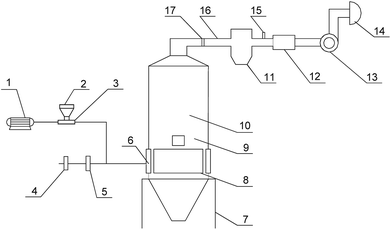
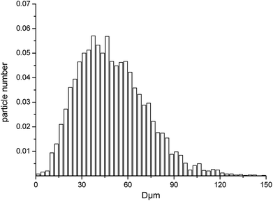
The test facility is illustrated in Fig. 1. It consists of a screw feeder, a furnace model, a test chamber, a suction fan and a bag filter. An air flow is induced from the duct to the furnace by the suction fan. Glass beads are fed via the screw feeder into the primary air duct. The degree of sphericity of the glass beads is greater than 95%. The density of the glass beads used was 2500 kg m−3. The particle size distribution obtained by PDA is shown in Fig. 2. The mean diameter was 42 μm. Since coal particles cannot meet the sphericity and reflectance characteristics required for PDA particle measurements, glass beads, which do meet these requirements, were used instead.
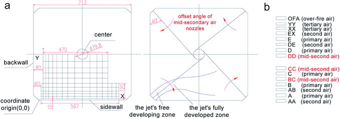
The full industrial-scale furnace studied in the experiments was designed for a 1025 t h−1 coal-fired boiler. For installation in the test facility, the furnace had to be scaled. As shown in Fig. 3a, a scale ratio of 1![[thin space (1/6-em)]](https://www.rsc.org/images/entities/char_2009.gif) :
:![[thin space (1/6-em)]](https://www.rsc.org/images/entities/char_2009.gif) 18 was employed for the model furnace and the cross-sectional area of the furnace model was 713 mm × 713 mm. The imaginary circle diameter was 39.9 mm. The initial angle of mid-secondary air nozzle in the scaled-down model is based on the full-size burner, and the initial angle between mid-secondary air nozzle and sidewall/backwall is 40°. The primary air velocity was 12.6 m s−1, the glass feeding rate of primary air nozzle was 15.6 kg h−1 and the secondary air velocity was 17.3 m s−1 in the furnace model. The design of the burners is shown in Fig. 3b. In this study, the burners included a total of 15 spouts. The mid-secondary air nozzles of three layers (BC, CC, DD) swung horizontally at the same time with the offset angles of primary air, other secondary/tertiary air and over-fire air kept invariant.
18 was employed for the model furnace and the cross-sectional area of the furnace model was 713 mm × 713 mm. The imaginary circle diameter was 39.9 mm. The initial angle of mid-secondary air nozzle in the scaled-down model is based on the full-size burner, and the initial angle between mid-secondary air nozzle and sidewall/backwall is 40°. The primary air velocity was 12.6 m s−1, the glass feeding rate of primary air nozzle was 15.6 kg h−1 and the secondary air velocity was 17.3 m s−1 in the furnace model. The design of the burners is shown in Fig. 3b. In this study, the burners included a total of 15 spouts. The mid-secondary air nozzles of three layers (BC, CC, DD) swung horizontally at the same time with the offset angles of primary air, other secondary/tertiary air and over-fire air kept invariant.
The offset angle of mid-secondary air nozzle is relative to the initial angle (case 1). The offset angles of mid-secondary air nozzle were 0°, 10°, 18°, 20°, 22° and 25°. So the angles between mid-secondary air nozzle and sidewall/backwall are 40°, 30°, 22°, 20°, 18° and 15°, respectively. The mixing rule of the two primary air flows in the C layer and furnace flow field was used to study the gas/solid mixing characteristics of the burner jet. By taking the central horizontal cross-section of the C layer as the initial section, the central section was measured as in Fig. 3a. The rectangular region on the horizontal cross-section of the nozzle was the measurement area. The left inferior vertex, 60 mm distant from the backwall and 10 mm distant from the sidewall, was the measurement origin of PDA, namely point (0,0). The directions of the sidewall and backwall are defined as the X axis and Y axis, respectively.
3. Results and discussion
3.1. Jet trajectory of primary air
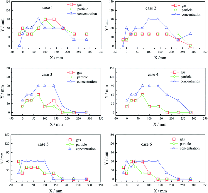
Fig. 4 shows the profiles of primary air jet trajectories in the furnace (the maximum gas/particle tangent velocity means the point on the jet center-line, and the maximum concentration point means the point on particle flow center-line). Under case 1, the particle flow diffuses gradually in the jet's free developing zone. Because of the wake vortices, particles are closer to the wall than the primary air. In the diffusion process, due to low jet flow rigidity, the primary air gradually tends to the wall with the deflection of particles. When the jet flow merges into the rotating airflow in the furnace, the gas trajectory coincides with the particle trajectory, which means the two phases rotate synchronously with a little tangential slippage in the jet's fully developed zone. The trajectory of the jet central line, represented by the line of points with maximum concentration, coincides with the gas trajectory in the jet's free developing zone and is closer to the water-cooled wall than the central line of gas/particle in the fully developed zone, which shows a tendency to pulverized coal divergence. It is obvious that the three items are in full accord through qualitative expression. They all show the jet flow process of keeping their own direction, parallel to the wall and deflecting to the wall.For the other cases, the jet central lines on the spout central section are qualitatively consistent with that of case 1. However, with the offset angle of mid-secondary air nozzles increasing, the jet deflects earlier in the furnace. For instance, the deflection position is at x = 200 mm in cases 1 and 2, x = 70 mm in case 3 and x = 40 mm in cases 4, 5 and 6. As a result, the diameter of tangential circle will increase and the combustion process will improve in the furnace. On the one hand, the space utility will improve, which will benefit the complete combustion of the pulverized coal, strengthen the exchange of mass, heat and momentum, delay the mixing between primary and secondary air and form fuel-enriched combustion to reduce thermal NOx in the early stages of combustion. On the other hand, the reducing atmosphere near the water-cooled wall will be weakened which is beneficial for preventing slagging and high-temperature corrosion.
It can also be seen that when the offset angle of mid-secondary air nozzles is increased, the maximum concentration line is always at the inner side of the other two lines, which illustrates that a good gas–solid two-phase flow field, characterized by air surrounding fuel, is formed. This is favorable for the occurrence of fuel-enriched combustion in the jet's free developing zone and reduction of thermal NOx. The air velocity and volume are also increased in the near-wall region which can form a relatively stronger oxidizing atmosphere to raise the sintering temperature, reduce slag and avoid high-temperature corrosion. For case 6, the pulverized coal concentration is lower in the jet's developing zone and equivalent near the sidewall region compared with case 3. In addition, the air velocity at the corresponding positions is lower than in case 3. As a result, the possibility of slagging is relatively reduced.
Fig. 5 shows a comparison of tangential velocities on the cross central line on the spout horizontal central section. The slippage between gas and particle is not obvious on the whole. The actual tangential circle diameter is smallest in case 1, and it increases with the increasing of offset angle of mid-secondary air nozzles from 0° to 10°, but there are little changes in cases 2–6. For all cases except case 1, the dimensionless wall velocity32 (the ratio of the air velocity in the cross central line of the furnace near the water-cooled wall to the maximum air velocity on the central line) is greater than 0.8, indicating that the diameter of the actual tangential circle is too large. The measured results of aerodynamic fields in the furnace of Anyang power plant's no. 9 boiler indicated that when the side-secondary air door opened from 35% to 100%, the ring diameter of strong air current changed from 7.8 m to 8 m. This means that the primary air rigidity can be enhanced by increasing the side-secondary air volume in a certain range.33 However, when further increasing the volume, the primary air was entrained by side-secondary air, which led to a larger diameter of the actual tangential circle in the furnace. This may be the reason for the larger actual tangential circle in this paper, being similar to our test results.
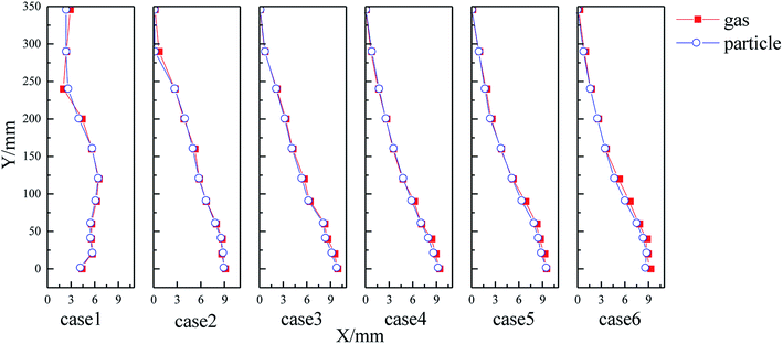 | ||
| Fig. 5 Profiles of gas/particle mean tangential velocity on the spout horizontal central section in cases 1–6. | ||
3.2. Mean tangential velocity of gas/particle
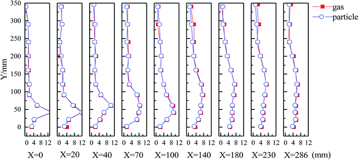
Fig. 6 shows the mean tangential velocities on the spout horizontal central section in case 1. It can be seen that the slippage between gas and particle is not obvious. The mean tangential velocity on the first three sections near the spout shows a unimodal distribution. With the development of the jet flow, the peak gradually moves towards the center of the furnace which illustrates the development process of jet flow. The main jet trajectory, reflected by the line connecting the peaks, indicates the process of jet development: the mean tangential velocities are smaller at the fire-facing side and back side of jet's free developing zone; near the peak point of the fourth section, the jet flow mixes intensely with the main flow upstream and subsequently enters the fully developed zone characterized with relatively gentle velocity distribution; the mean tangential velocity decreases gradually from outside to center in the quasi-solid zone and the velocity is relatively high in the main air swirl flow; compared with the flow in the quasi-solid zone, the velocity decreases gradually from the center to the outside in the quasi-equipotential zone, the absolute velocity being higher. As a result, the static pressure in the furnace gradually increases from center to outside, i.e., the pressure is higher on the periphery. The rotating flare surrounded by air flow has a good flame with certain shape and position, which led to a steady combustion field.Fig. 7 compares the mean tangential velocities of particles on the spout horizontal central section in typical cases 1, 2, 3 and 6. For the four cases, the changing velocity trends are similar, but the velocity near the wall obviously increases with an increase in offset angle of the mid-secondary air nozzles. The reason is that the secondary air entrains primary air and the diameter of the actual tangential circle thereby increases.34
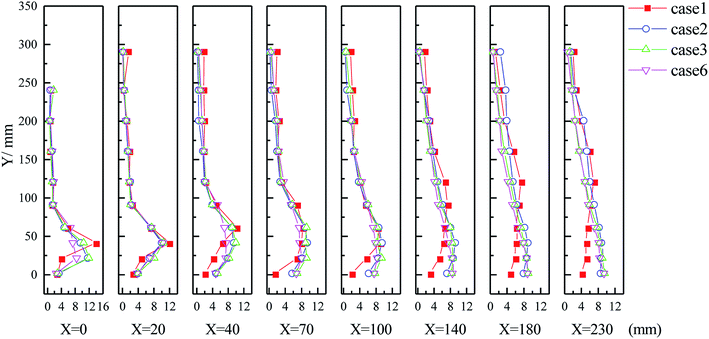 | ||
| Fig. 7 Profiles of tangential velocity (m s−1) of particles on spout central section in cases 1, 2, 3 and 6. | ||
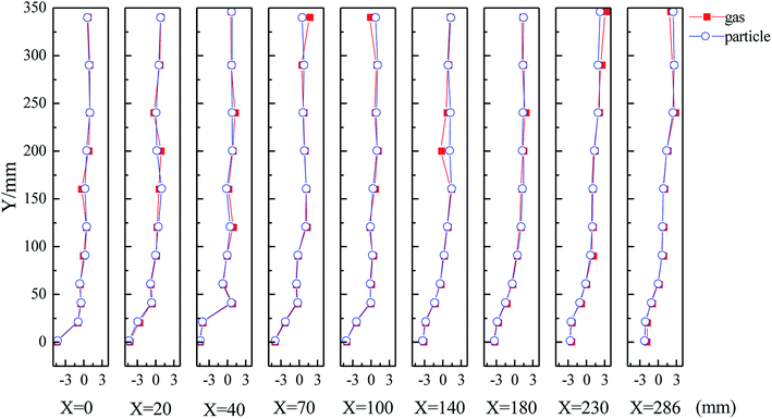
Fig. 8 shows the mean axial velocities on the horizontal central section of the spout in case 1. The other 5 cases have similar changing patterns. It can be seen that the slippage between gas and particle is not obvious. The valley on the section Y = 0 mm indicates that the air near the wall moves downward. At the beginning, the axial velocity is downward with a large velocity gradient in the sidewall region which indicates that the particles have a tendency to deposit downward near the wall. This may be caused by kinetic energy loss when the particles impact the sidewall.34 Then the velocity has a uniform distribution along the back wall, and the farther it is from the origin, the smaller the velocity is and the bigger is the range. The curve shows a “J” shape which indicates that the mean axial velocity is downward. The positive axial velocity component in the main swirl air zone and quasi-solid zone indicates that the air flow has a tendency to move upward.
3.3. Reynolds stress on horizontal section
Fig. 9 shows Reynolds stress in case 1 and case 3. The Reynolds stress in the u–v direction is perpendicular to that in the v–w direction. The strong material exchange in a large vortex at the center of the furnace, a large shear vortex at the fire-facing side and the wake vortex at the back-fire side can be seen from the distribution of Reynolds stress. The large vortex in the furnace is mainly located in the horizontal direction, so the shear stress in the u–v direction acts in a wide range. Because the jet flow sticks to the wall for a short time, shear stress is caused by the large vortex in the furnace except for the larger Reynolds stress caused by the wake vortex at the back-fire side.34,35 Besides, a greater Reynolds stress and turbulent kinetic energy exist at the impacting point of the jet and upstream as a result of the shear vortex and attaching vortex at the fire-facing side. The Reynolds stress in the v–w direction shows intense material exchange between the primary air jet and the transverse jet flow, i.e., the fire-facing side of the primary air jet has a larger shear stress. Besides, as shown in Fig. 9, with the increasing of offset angle of mid-secondary air nozzles, the vortex on the fire-backing side in the u–v direction decreases. This can avoid airflow short circuit. Meanwhile, the region with large Reynolds stress moves down and the angle between this region and the X-axis decreases. It can be demonstrated that the jet deflection is in advance and the actual tangential circle diameter is bigger.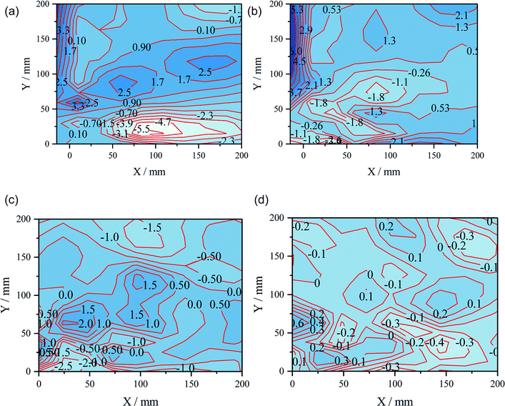 | ||
| Fig. 9 Equipotential maps of Reynolds stress (Pa). (a) u–v Reynolds stress in case 1; (b) v–w Reynolds stress in case 1; (c) u–v Reynolds stress in case 3; (d) v–w Reynolds stress in case 3. | ||
3.4. Concentration of gas/particle two-phase flow field
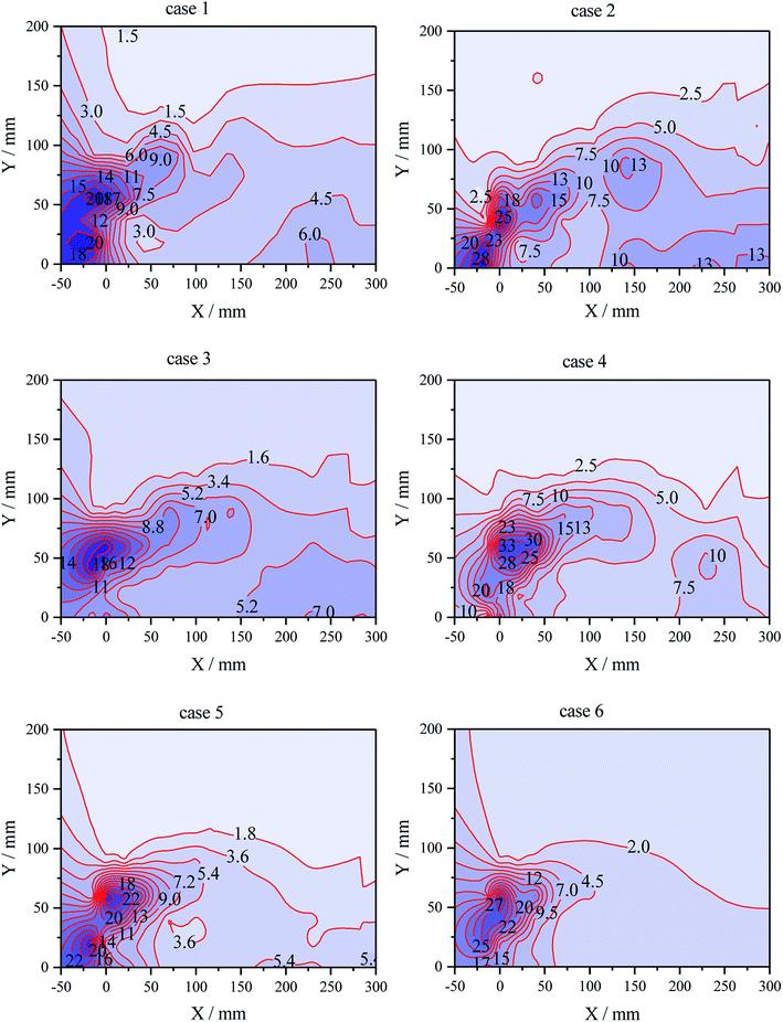
Fig. 10 shows the equipotential map of particle volume concentration on the spout horizontal central section for cases 1–6. In order to make the six cases comparable, the data for each case are multiplied by a coefficient to equate the concentration sum of all points for each case, which makes the concentration dimensionless. The concentration distribution shows a single peak in cases 3, 4 and 6, and two peaks in cases 1, 2 and 5. Because the main peak is located in the initial period of the jet flow, the location of the peak does not change with the change in offset angles of the mid-secondary air nozzles in three of the cases (cases 3, 4 and 6).It can be seen that there are many coal particles around the spout and the furnace corners, indicating that the turbulent diffusion of the primary air jet is strong. One reason is that the deflected burner jet loses less momentum after collision with the side burner jet.36 Another reason is that the free space is bigger and the secondary vortex is stronger in the furnace corner compared with the main vortex in the furnace center, which has a strong entrainment effect on the coal particles.15 So the concentration distribution shows two peaks in cases 1, 2 and 5.
The secondary air jet is relatively strong and can entrain the primary air jet with an increase in the offset angle of the mid-secondary air nozzles, which results in the primary air jet deflection in advance and larger diameter of the tangential circle. At the same time, the oxygen-poor combustion forms a reducing atmosphere in the furnace center which is beneficial for NOx reduction.
It also can be seen that with the increasing offset angle of the mid-secondary air nozzles, the concentration gradient increases near the concentration peak.
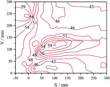
Fig. 11 shows the distribution of mean particle size on the spout cross-section in case 1 in order to explain the effect of the wake vortex on the actual concentration diffusion. Based on the results shown in Fig. 10, the concentration distribution in cases 3, 4 and 6 is different from that in cases 1, 2 and 5. However, the wake vortex was observed only in cases 1, 2 and 5. So we just explain the effect of the wake vortex on the actual concentration diffusion in case 1. Because the small particles have better following performance and are more easily entrained by the wake vortex (the larger particles are taken into the main flow region), the mean particle size is smaller at the back-fire side of the jet, which indicates that the wake vortex plays a role in the actual concentration diffusion.
4. Conclusions
(1) With an increase in offset angle of the mid-secondary air nozzles, the diameter of actual tangent circles will increase, which is beneficial for combustion space utility and complete burning for pulverized coal; with an increased offset angle, the line with maximum concentration is basically at the inner side of the line with maximum velocity and a good gas/particle two-phase flow field with air-surrounding-fuel is formed.(2) With an increase in offset angle of the mid-secondary air nozzles, the diameter of the tangent circle increases. The rigidity of jet flow, the stability of airflow and the disturbance are also enhanced, which results in a better blend of jet tail.
(3) The mean tangential velocity distribution on the spout horizontal cross-section shows a single peak and the slippage is not obvious in axial and tangential directions.
(4) The shear vortex at the fire-facing side and the wake vortex at the back-fire side result in larger shear stress, greater turbulent kinetic energy and intense energy/mass exchange at both sides of the jet. With an increase in offset angle of the mid-secondary air nozzles, the vortex at the back-fire side diminishes to avoid a short circuiting of the airflow.
(5) The position of the main concentration peak is maintained invariant in the jet's free developing zone. Besides, with an increase in offset angle of the mid-secondary air nozzles, the particle concentration peak near the water-cooled wall increases, the distance from the peak to front wall increases and the jet flow diffusion in later stages is improved.
Conflicts of interest
There are no conflicts to declare.Acknowledgements
The authors thank the National Key R&D Program of China (no. 2017YFB0602904) for financial support.References
- D. X. Zhang, P. Liu, X. L. Lu, L. L. Wang and T. Y. Pan, Fuel Process. Technol., 2016, 141, 117–122 CrossRef.
- C. F. You and X. C. Xu, Energy, 2010, 35, 4467–4472 CrossRef.
- M. U. Degereji, D. B. Ingham, L. Ma, M. Pourkashanian and A. Williams, Fuel, 2012, 101, 171–178 CrossRef.
- Z. C. Chen, Z. Q. Li, J. P. Jing, F. Q. Wang, L. Z. Chen and S. H. Wu, Fuel Process. Technol., 2008, 89, 958–965 CrossRef.
- X. C. Xu, C. H. Chen, H. Y. Qi, R. He, C. F. You and G. M. Xiang, Fuel Process. Technol., 2000, 62, 153–160 CrossRef.
- Z. C. Chen, Z. Q. Li, F. Q. Wang, J. P. Jing, L. Z. Chen and S. H. Wu, Fuel, 2008, 87, 2102–2110 CrossRef.
- S. C. Kung, Corrosion, 2014, 70, 749–763 CrossRef.
- H. S. Shim, J. R. Valentine, K. Davis, S. I. Seo and T. H. Kim, Fuel, 2008, 87, 3353–3361 CrossRef.
- H. Liu, Y. H. Liu, G. Z. Yi, L. Nie and D. F. Che, Energy Fuels, 2013, 27, 5831–5840 CrossRef.
- A. A. Bhuiyan, A. S. Blicblau and J. Naser, J. Energy Inst., 2017, 90, 838–854 CrossRef.
- H. H. Ma, L. Zhou, S. X. Ma and H. J. Du, Appl. Therm. Eng., 2017, 124, 865–870 CrossRef.
- Y. H. Song, J. H. Pohl, J. M. Beer and A. F. Sarofim, Combust. Sci. Technol., 1982, 28, 31–39 CrossRef.
- Z. Q. Li, R. Sun, L. Z. Chen, Z. X. Wan, S. H. Wu and Y. K. Qin, Fuel, 2002, 81, 829–835 CrossRef.
- R. Luo, Y. F. Zhang, N. Li, Q. L. Zhou and P. Sun, Exp. Therm. Fluid Sci., 2014, 54, 136–150 CrossRef.
- J. P. Jing, Z. Q. Li, Q. Y. Zhu, Z. C. Chen, L. Wang and L. Z. Chen, Energy, 2011, 36, 258–267 CrossRef.
- D. F. Tian, L. J. Zhong, P. Tan, L. Ma, Q. Y. Fang, C. Zhang, D. P. Zhang and G. Chen, Fuel Process. Technol., 2015, 138, 616–628 CrossRef.
- S. G. Ti, Z. C. Chen, Z. Q. Li, K. Min, Q. Y. Zhu, L. Z. Chen and Z. F. Wang, Appl. Therm. Eng., 2017, 125, 951–962 CrossRef.
- H. W. Chen, Z. X. Feng, L. S. An, Z. Z. Li, Q. L. Huang, Y. M. Pang and Y. H. Li, Proceedings of the CSEE, 2007, 27, 11–15 Search PubMed.
- W. H. Feng, Y. Bing, Z. H. Cai and Z. C. G. An, Power Equipment, 2003, 17, 11–14 Search PubMed.
- F. U. Yi-Jun, X. J. Zhang, R. Zhang and F. U. Wei-Biao, Electr. Power, 2006, 39, 49–52 Search PubMed.
- J. R. Fan, Z. H. Xia, X. Y. Zhang and K. F. Cen, Fuel, 2000, 79, 1853–1860 CrossRef.
- S. Rui, Chin. J. Mech. Eng., 2004, 40, 35 Search PubMed.
- C. Moon, Y. Sung, S. Eom and G. Choi, Exp. Therm. Fluid Sci., 2015, 62, 99–108 CrossRef.
- R. Weber, Symposium on Combustion, 1996, vol. 26, pp. 3343–3354 Search PubMed.
- D. Shin, S. Park, B. Jeon, T. Yu and J. Hwang, Journal of Mechanical Science and Technology, 2006, 20, 2284–2291 CrossRef.
- T. M. Pickett, R. E. Jackson and D. R. Tree, Combust. Sci. Technol., 1999, 143, 79–107 CrossRef.
- V. M. Zemlianskii, J. Aerosol Sci., 1996, 27, S325–S326 CrossRef.
- S. Moon, C. Bae, J. Choi and E. Abo-Serie, Fuel, 2007, 86, 400–409 CrossRef.
- A. W. Hubner, M. J. Tummers, K. Hanjalic and T. H. van der Meer, Exp. Therm. Fluid Sci., 2003, 27, 481–489 CrossRef.
- X. F. Liu, W. H. Doub and C. N. Guo, Int. J. Pharm., 2012, 423, 235–239 CrossRef PubMed.
- L. Zhang and J. Kulon, IEEE Trans. Instrum. Meas., 2011, 60, 1397–1407 CrossRef.
- F. Ren, Z. Q. Li, Z. C. Chen, Z. X. Xu and G. H. Yang, Fuel, 2011, 90, 997–1003 CrossRef.
- Y. G. Zhou, M. C. Zhang, T. M. Xu and S. E. Hui, Energy Fuels, 2009, 23, 5375–5382 CrossRef.
- M. Kuang, Z. Q. Li, Q. Y. Zhu and H. Y. Zhang, Int. J. Therm. Sci., 2013, 68, 148–157 CrossRef.
- M. Kuang, Z. Q. Li, P. F. Yang, J. Z. Jia and Q. Y. Zhu, Fuel Process. Technol., 2011, 92, 1261–1271 CrossRef.
- M. Kuang, Z. Q. Li, Q. Y. Zhu, Y. Wang, L. Z. Chen and Y. Zhang, Energy, 2012, 42, 411–423 CrossRef.
| This journal is © The Royal Society of Chemistry 2018 |

