 Open Access Article
Fabrication of novel electrochemical sensors based on modification with different polymorphs of MnO2 nanoparticles. Application to furosemide analysis in pharmaceutical and urine samples
Mohamed I. Saida,
Azza H. Rageh *b and
Fatma A. M. Abdel-aalb
aDepartment of Chemistry, Faculty of Science, Assiut University, Assiut 71516, Egypt
bDepartment of Pharmaceutical Analytical Chemistry, Faculty of Pharmacy, Assiut University, Assiut 71526, Egypt. E-mail: azhesham@yahoo.com; azzarageh@aun.edu.eg; Fax: +20 882 080774; Tel: +20 882 411009
First published on 23rd May 2018
Abstract
A novel MnO2 nanoparticles/chitosan-modified pencil graphite electrode (MnO2 NPs/CS/PGE) was constructed using two different MnO2 polymorphs (γ-MnO2 and ε-MnO2 nanoparticles). X-ray single phases of these two polymorphs were obtained by the comproportionation reaction between MnCl2 and KMnO4 (molar ratio of 5![[thin space (1/6-em)]](https://www.rsc.org/images/entities/char_2009.gif) :
:![[thin space (1/6-em)]](https://www.rsc.org/images/entities/char_2009.gif) 1). The temperature of this reaction is the key factor governing the formation of the two polymorphs. Their structures were confirmed by powder X-ray diffraction (XRD), Fourier transform infrared (FTIR) and energy dispersive X-ray (EDX) analysis. Scanning electron microscopy (SEM) was employed to investigate the morphological shape of MnO2 NPs and the surface of the bare and modified electrodes. Moreover, cyclic voltammetry and electrochemical impedance spectroscopy (EIS) were used for surface analysis of the modified electrodes. Compared to bare PGE, MnO2 NPs/CS/PGE shows higher effective surface area and excellent electrocatalytic activity towards the oxidation of the standard K3[Fe(CN)6]. The influence of different suspending solvents on the electrocatalytic activity of MnO2 was studied in detail. It was found that tetrahydrofuran (THF) is the optimum suspending solvent regarding the peak current signal and electrode kinetics. The results reveal that the modified γ-MnO2/CS/PGE is the most sensitive one compared to the other modified electrodes under investigation. The modified γ-MnO2/CS/PGE was applied for selective and sensitive determination of FUR. Under the optimized experimental conditions, γ-MnO2/CS/PGE provides a linear response over the concentration range of 0.05 to 4.20 μmol L−1 FUR with a low limit of detection, which was found to be 4.44 nmol L−1 (1.47 ng mL−1) for the 1st peak and 3.88 nmol L−1 (1.28 ng mL−1) for the 2nd one. The fabricated sensor exhibits a good reproducibility and selectivity and was applied successfully for the determination of FUR in its dosage forms and in spiked urine samples with good accuracy and precision.
1). The temperature of this reaction is the key factor governing the formation of the two polymorphs. Their structures were confirmed by powder X-ray diffraction (XRD), Fourier transform infrared (FTIR) and energy dispersive X-ray (EDX) analysis. Scanning electron microscopy (SEM) was employed to investigate the morphological shape of MnO2 NPs and the surface of the bare and modified electrodes. Moreover, cyclic voltammetry and electrochemical impedance spectroscopy (EIS) were used for surface analysis of the modified electrodes. Compared to bare PGE, MnO2 NPs/CS/PGE shows higher effective surface area and excellent electrocatalytic activity towards the oxidation of the standard K3[Fe(CN)6]. The influence of different suspending solvents on the electrocatalytic activity of MnO2 was studied in detail. It was found that tetrahydrofuran (THF) is the optimum suspending solvent regarding the peak current signal and electrode kinetics. The results reveal that the modified γ-MnO2/CS/PGE is the most sensitive one compared to the other modified electrodes under investigation. The modified γ-MnO2/CS/PGE was applied for selective and sensitive determination of FUR. Under the optimized experimental conditions, γ-MnO2/CS/PGE provides a linear response over the concentration range of 0.05 to 4.20 μmol L−1 FUR with a low limit of detection, which was found to be 4.44 nmol L−1 (1.47 ng mL−1) for the 1st peak and 3.88 nmol L−1 (1.28 ng mL−1) for the 2nd one. The fabricated sensor exhibits a good reproducibility and selectivity and was applied successfully for the determination of FUR in its dosage forms and in spiked urine samples with good accuracy and precision.
1. Introduction
The use of either chemically or physically modified electrodes, which are based on nanostructured materials such as metal or metal oxide nanoparticles in addition to graphene, graphene oxide, carbon nanotubes and polymers,1–14 has attracted the interest of many researchers to explore their utilization in electrochemical analysis of various substances of biological, environmental or pharmaceutical interest due to the outstanding physical and catalytic properties of these materials.Because of the structural variability and different oxidation states of Mn (i.e., +2, +3 and +4), MnO2 has wide applications in various areas. Manganese(IV) oxide (MnO2) has several polymorphs such as α-, β-, γ-, δ- and ε-MnO2, which possess the same basic structural units ([MnO6] octahedrons); however, they differ in the way by which these units are connected.15,16 MnO2 was utilized as a chemical sensor or bio-sensor together with glassy carbon electrode (GCE),16–19 glassy carbon paste electrode (GCPE)20,21 or carbon paste electrode (CPE).22,23 The difference between these polymorphs in the field of electrochemical analysis has not been discussed previously. In the present study, two different polymorphs (γ-MnO2 and ε-MnO2) are selected to be discussed. The efficiency of γ- and ε-MnO2 as modifiers for electrode surfaces and subsequently their influence on enhancement of the electroanalytical signal of some selected analytes will be the main focus of the current work.
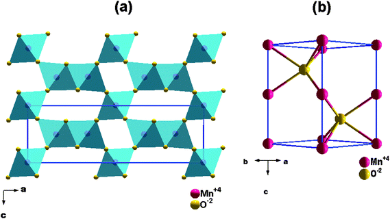
The γ-MnO2 (nsutite minerals) polymorph has a structure which is composed of MnO6 octahedrons that share their edges and corners to form tunnels extended in the c direction over the structure (Fig. 1a).24 Indeed, γ-MnO2 structure is considered as a random microscopic intergrowth of β-MnO2; pyrolusite (r) with 1 × 1 tunnels and R-MnO2; ramsdellite (R) with 1 × 2 tunnels.25 De Wolff has quantified the relative amount of them as Pr, i.e. replacement of a single chain of octahedrons by double chains25 which is known as “De Wolff defect”. Chabre and Pannetier26 proposed a way for Pr estimation, and presented the parameter Tw (defined later by Mt) which identifies the percentage of “microtwinning” (change of ca. 60/120° in the c-axis direction) and represents the microtwinning of the (021) and (061) growth planes. They referred to the possibility of continuous evolution (theoretical probability) from a γ-MnO2 structure with only De Wolff defects to a ε-MnO2 structure (Fig. 1b). Hexagonal symmetry arises as a result of extreme twinning (the twinning not being dependent on the De Wolff defects). In this case, the double chains of R and/or single chains of r parallel to the c-axis undergo a lot of changes in direction at ca. 60/120° upon twinning leading to a mean hexagonal structure.
Characteristic features concomitant with the structure of γ-MnO2 are the cationic vacancies, manganese cations with low valence (MnIII), and structural water existing as protons linked to oxide anions which compensate for the charge deficiency caused by cationic vacancies and Mn(III) ions.26–29 Accordingly, the chemical composition of γ-MnO2 has been described as:30
| (Mn4+)1−x−y·(□)x·(Mn3+)y·(O2−)2−4x−y·(OH−)4x+y |
Modification of disposable pencil graphite electrodes (PGE) with MnO2 NPs has not been reported so far, even though PGE have several advantages over commercial metal- or other carbon-based electrodes such as the low cost, availability, low background current, wide potential window and ease of modification besides the renewable and reproducible surface.31 These unique properties have been reflected through the work reported by Wang and Kawde,32 which showed that PGE exhibits favourable responses over GCE for stripping detection of DNA and RNA. Despite these distinctive properties, the most commonly used electrodes, which are modified with metal oxide nanoparticles, are based on CPEs or GCPEs. Therefore, it was the main task of the present work to investigate the modification of PGE via physically attaching MnO2 NPs to the electrode surface.
From the field of organic synthesis, it is a known fact that the choice of solvent in the oxidation of organic compounds with manganese dioxide is very important. Solvents play a crucial role in activation of MnO2 towards oxidation of organic compounds.33 The solvents most widely used for oxidation with active manganese dioxide at room temperature are saturated or chlorinated hydrocarbons, benzene, toluene, THF, ethylacetate, etc.33 On the other hand, it was reported that water and other hydrogen-bond donor solvents (protic solvents) and, to a lesser extent, polar aprotic solvents have a strong deactivating effect on active MnO2 as they can negatively influence the oxidation power of active MnO2.34,35 This results in the prevention of adsorption of analytes to oxidatively active polar sites on the surface of MnO2.35
From a literature survey, it is obvious that the influence of solvents on activation of metal oxide nanomaterials, especially MnO2 NPs, used for electrochemical applications, is passed over or underestimated. According to the previously mentioned background, it was the target to study and provide an explanation for the influence of different suspending organic solvents on the electrocatalytic activity of MnO2 NPs (as a modifier for PGE). In this regard, it is worth mentioning that classical CPEs cannot be used for this investigation as they suffer from being unstable in a medium containing high percentage of organic solvents, which are capable of dissolving the binding oil, making the paste friable.36
Chitosan is a biodegradable polysaccharide biopolymer that is chemically produced by partial deacetylation of natural chitin.37 Its unique properties such as good adhesive properties, cheapness, ability to be chemically modified due to the presence of hydroxyl and reactive amino functional groups in addition to excellent film-forming ability, nontoxicity, biocompatibility, pH-dependent chargeability and solubility in aqueous media justify its use as an immobilization matrix for biosensors.16,18,37–40 Here, it was decided to combine the advantages of using chitosan as binder together with excellent electrocatalytic activity of MnO2 NPs for fabrication of novel sensors based on PGE.
Furosemide (FUR), which is chemically known as 4-chloro-N-furfuryl-5-sulfamoylanthranilic acid, is a potent loop diuretic. It is used mainly for the treatment of hypertension and edema associated with chronic renal failure and congestive heart failure. It exerts its action predominantly in the nephron by inhibition of NaCl/KCl/2Cl transporter in the loop of Henle preventing tubular re-absorption of sodium and results ultimately in diuresis. The prompt action of FUR is attributed to rapid absorption after oral administration (within one hour) and its diuretic effect persists for about 6–8 hours.41 However, if the therapeutic dose of FUR is not carefully monitored, it might result in depletion of sodium, body water and other minerals, thus affecting negatively the ion–water balance in the human body.42,43 Therefore, the development of analytical methodologies to monitor its concentration is highly important.
Several analytical methods have been reported for the determination of FUR in different matrices such as pharmaceutical dosage forms, plasma and urine samples. The developed methods for determination of FUR include chromatographic methods such as high-performance liquid chromatography,44,45 micellar liquid chromatography46 and liquid chromatography tandem mass spectrometry,47 capillary electrophoresis,48 and spectrofluorimetric and spectrophotometric methods.49–52 If compared with other reported methods, electrochemical methods have several advantages such as simplicity, low operational cost, high sensitivity and short analysis time. There are few electrochemical methods that were reported for the determination of FUR;53–59 however, all of them lack the simplicity and selectivity to the negatively charged FUR.
In the current study, two novel, highly sensitive and selective MnO2 nanoparticles/chitosan-modified pencil graphite electrodes (MnO2 NPs/CS/PGE), constructed using two different polymorphs of MnO2 NPs, are described. The synthesis and characterization of the two polymorphs are discussed. For the first time, the effect of solvents on the electrocatalytic activity of MnO2 NPs is investigated in detail and the electrochemical activities of the modified electrodes are calculated. The applicability and selectivity of the fabricated electrodes are demonstrated through the sensitive determination of FUR in its dosage forms and in spiked urine samples.
2. Experimental
2.1. Materials and reagents
Potassium permanganate, manganese chloride, graphite powder, paraffin oil, methanol, ethanol, acetonitrile, N,N-dimethylformamide (DMF), tetrahydrofuran (THF), 1,4-dioxane, toluene, chloroform and diethylether were purchased from Merck, Darmstadt, Germany. FUR standard (purity 99.2%), boric acid, sodium hydroxide, potassium chloride, acetic acid and phosphoric acid were obtained from Sigma-Aldrich, Steinheim, Germany. Chitosan (CS, MW 5–6 × 10⁵, >90% deacetylation), potassium ferricyanide and hydrochloric acid were from Fluka, Buchs, Switzerland. All chemicals were of analytical reagent grade and were used without further purification. FUR ampoules, i.e., Lasix (20 mg per ampoule), were purchased from sanofi-aventis, Egypt, under licence of sanofi-aventis, Germany. Methanol was used for the preparation of stock and working standard solutions of FUR and these solutions were kept protected from light at 4 °C for one week. Double distilled water was used throughout this work. Drug-free human urine samples, obtained from five healthy volunteers, were centrifuged and filtered through 0.45 μm membrane filter and stored frozen until the assay. All procedures performed in this study involving human participants were in accordance with the ethical standards of Assiut University research committee and with the 1964 Helsinki Declaration and its later amendments and were approved by the Department of Pharmaceutical Analytical Chemistry, Faculty of Pharmacy, Assiut University. For experiments with human urine, informed consents were obtained from the volunteers.2.2. Instrumentation
Electrochemical studies were carried out using a Princeton VersaSTAT MC (VersaSTAT 3, Model RE-1, Princeton Applied Research, AMETEK, USA). The electrochemical study was performed by using a conventional three-electrode system consisting of a bare/modified PGE as working electrode, the counter electrode was a platinum wire, while the reference electrode was Ag/AgCl (saturated KCl). Pencil graphite was available as pencil lead from Rotring Co. Ltd (Germany, S0312670 of type 2B, B, HB, H and 2H). All leads possessed a diameter of 0.5 mm and were used as received.The pH values of buffer solutions were recorded using a pH meter (Hanna Instruments Brazil, São Paulo, SP, Brazil). All measurements were done at room temperature.
For morphological characterization of prepared NP-modified PGEs, samples were coated with 10 nm thick gold by using a PECS fine grinding and coating device (Gatan, Model 682, UK). Then a scanning electron microscopy (SEM) instrument (JEOL JSM-5400 LV, Oxford, USA) was used.
2.3. Preparation of the sensors
![[thin space (1/6-em)]](https://www.rsc.org/images/entities/char_2009.gif) :
:![[thin space (1/6-em)]](https://www.rsc.org/images/entities/char_2009.gif) 1. To the mixture 100 mL of dist. H2O was added and the reaction mixture was stirred vigorously for 1 h at room temperature. The reaction was repeated once again at 100 °C. The final pH of the reaction mixture was measured after the termination of reaction as ∼1.4. The obtained products were separated by centrifugation (6000 rpm for 5 min), washed many times with deionized water and dried in air at 60 °C. Formation of MnO2 NPs can take place according to the following equation:
1. To the mixture 100 mL of dist. H2O was added and the reaction mixture was stirred vigorously for 1 h at room temperature. The reaction was repeated once again at 100 °C. The final pH of the reaction mixture was measured after the termination of reaction as ∼1.4. The obtained products were separated by centrifugation (6000 rpm for 5 min), washed many times with deionized water and dried in air at 60 °C. Formation of MnO2 NPs can take place according to the following equation:| 2KMnO4 +3MnCl2 + 2H2O → 5MnO2 + 2KCl + 4HCl | (1) |
SEM was carried out using a JEOL JSM-7500F field emission scanning electron microscope at an accelerating voltage of 2–5 kV. All samples were sputtered with platinum prior to observation.
In our work Fourier transform infrared (FT-IR) spectra were recorded in the wavenumber range 4000–400 cm−1 with a TENSOR 37 (Bruker Optics) spectrometer.
EDX measurements for the samples were done using a CamScan scanning electron microscope equipped with EDX system from Noran Instruments. The samples were mounted on a holder coated with a carbon film; quantitative measurements for the constituents of the sample were done by single point measurement. Several measurements were done thereafter. For each constituent atom the average of the measurements was then estimated.
2.4. Impedance measurements
Electrochemical impedance spectroscopy (EIS) measurements were conducted using an excitation AC signal of 10 mV amplitude and a frequency range from 1 Hz to 10 kHz in the presence of 1.0 mmol L−1 K3[Fe(CN)6] in 0.1 mol L−1 KCl adjusted to pH 2.5 using 1 mol L−1 HCl. EIS results were fitted to a Randles indented equivalent circuit. Zview software was used to analyze the EIS results (Zview version 3.1c).3. Results and discussion
3.1. Characterization of MnO2 NPs
The crystal structure of the obtained MnO2 NPs was investigated by XRD analysis. XRD pattern of the sample obtained at room temperature (Fig. 2b) shows two main reflections at 2θ = 37 and 65°. The pattern is related to a clean epsilon phase of manganese dioxide (akhtenskite with space group P63/mmc) as compared to a reference pattern (ICSD-76430, hexagonal) shown in Fig. 2a. The broad reflections are considered as an indication for the low crystallinity of the obtained nanoparticles. The average particle size estimated from band broadening using Scherrer's equation is 8.5 nm. On the other hand, XRD pattern of the sample obtained at 100 °C and illustrated in Fig. 2d shows reflections which are matched with those of γ-MnO2 (nsutite with space group Pnam) as compared to the reference JCPDS card (no. 14-0644, orthorhombic) shown in Fig. 2c. The main particle size for this sample is 12 nm.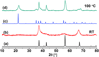 | ||
| Fig. 2 XRD diffractograms of ε-MnO2 (b) and γ-MnO2 (d). Also shown are reference patterns for ε-MnO2 (a) and γ-MnO2 (c). | ||
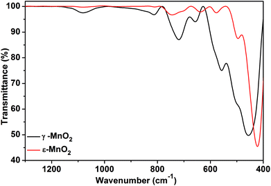
FT-IR spectra of both phases are presented in Fig. 3. For akhtenskite, six absorption bands in the range of 400–800 cm−1 are observed; the bands are correlated with the lattice vibrations of Mn–O within MnO6 octahedrons. The absorption bands observed in the FT-IR spectrum of nsutite are attributed to Mn–O vibrations in MnO6 octahedrons as well and match with those found in the literature.60 The band at 1626 cm−1 is ascribed to O–H vibration, whereas the band appearing at 1050 cm−1 represents vibration due to interaction of Mn with OH.61 The shift in the absorption peaks of akhtenskite relative to those of nsutite gives a hint about the structural divergence between them.
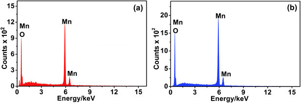
The elemental composition of the MnO2 phases was identified using EDX analysis. The spectra are depicted in Fig. 4, and the data extracted from EDX analysis are listed in Table 1. In fact, nsutite has a small tunnel size (0.24 nm × 0.48 nm) which cannot accommodate the large K cations. Accordingly, K cation insertion into such tunnels is not probable. Indeed, no peak characteristic of the presence of K cations can be detected in the EDX spectrum of nsutite. The elemental analysis of Mn and O atoms is typical for MnO2 formula as one can see from Table 1. Similarly, the EDX spectrum of akhtenskite does not show any peak corresponding to the existence of K cations, only Mn and O peaks are present. The elemental data shown in Table 1 correspond to MnO2 formula.
| Mn (%) | O (%) | K (%) | Cl (%) | |
|---|---|---|---|---|
| ε-MnO2 | 36.15 | 63.7 | 0.15 | 0.0 |
| γ-MnO2 | 36.64 | 63.11 | 0.11 | 0.13 |
3.2. Morphology investigation
The morphology of the different MnO2 phases was identified using SEM. The SEM images are depicted in Fig. 5. Exploration of the morphological shape of ε-MnO2 sample indicates spherical-like aggregates (Fig. 5a) which have a diameter falling in the range of 500–750 nm. The spheres are composed of many nanosheets with ∼9 nm thickness, which are inclined to each other as seen from Fig. 5b. A plate-like morphology is observed for nsutite, the plates having a thickness of about 5 nm and a diameter of 100 nm. These plates do not have a regular shape as illustrated in Fig. 5c.3.3. Preliminary investigations
We started our investigations by trying different electrode types including different types of PGE (2B, B, HB, H and 2H), GCE, CPE and GCPE using 1.0 mmol L−1 K3[Fe(CN)6] in 0.1 mol L−1 KCl, pH 2.5, as standard. The highest current intensity (results not shown) was obtained using PGE. Optimized parameters are: scan potential, −0.2 to 0.6 V (vs. Ag/AgCl electrode); scan rate, 100 mV s−1; and deposition time, 10 s. After trying various types of pencil lead, it was found that the H-type provides the most favourable signal with low background noise. This type was employed for further investigations.32The next step was to attach MnO2 NPs to PGE. Firstly, Kawde's procedure62 was adopted for which it was reported that immersion of bare PGE in a synthesized gold nanoparticle (AuNP) solution for 15 min at elevated temperature (75 °C) permits efficient attachment of AuNPs to the electrode surface if compared to the same procedure carried out at room temperature (minimal attachment). In the current study, PGE was immersed in the synthesized MnO2 NP suspension (without removing initial reactants) for 15 min either at room temperature or at 75 °C; however, this procedure was unsuccessful to attach MnO2 NPs to the electrode surface as reflected by the electroanalytical signal obtained using 1.0 mmol L−1 K3[Fe(CN)6] in 0.1 mol L−1 KCl (no difference between the bare PGE and the immersed electrodes).
3.4. Effect of solvent type using MnO2-modified PGE (MnO2/PGE)
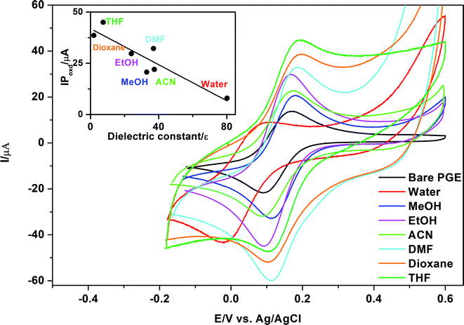
As Kawde's procedure was non-transferable to our case,62 the idea was to study the influence of MnO2 NPs on the oxidation peak current of K3[Fe(CN)6] after suspending MnO2 NPs in different solvents types. The selected solvents show differences in their dielectric constants and relative polarity as indicated in Table 2.63| Solvent | Relative polarity | Dielectric constant, ε | IPoxd, μA |
|---|---|---|---|
| Water | 1.000 | 80.1 | 8.0 |
| Methanol | 0.762 | 33.0 | 20.7 |
| Ethanol | 0.654 | 24.0 | 29.7 |
| Acetonitrile | 0.460 | 37.5 | 22.0 |
| DMF | 0.386 | 37.0 | 32.2 |
| THF | 0.207 | 7.5 | 44.9 |
| 1,4-Dioxane | 0.164 | 2.0 | 38.6 |
| Diethyl ether | 0.117 | 4.3 | No peak |
| Chloroform | 0.259 | 4.8 | No peak |
| Toluene | 0.099 | 2.4 | Distorted peak |
In the current study, it was a major task to investigate the effect of different types of solvents on activation of MnO2 NPs and consequently their effect on oxidation of K3[Fe(CN)6] using the peak current as a criterion for selection of the best solvent type. It is clear from Table 2 and Fig. 6 that polar protic solvents such as water, methanol or ethanol give lower current signals than aprotic solvents such as DMF, THF or 1,4-dioxane. On the other hand, irregular or distorted peaks were obtained using non-polar solvents such as chloroform, diethylether and toluene. A good correlation (r = 0.91) exists between either the relative polarity or dielectric constants63 of the examined solvents and the peak currents (Table 2). The highest peak current was obtained using THF as a suspending solvent. This result can explain why THF is used frequently with MnO2 in catalysis. Being a polar aprotic solvent, we can assume that THF does not contribute to any hydrogen bond formation with abundant surface OH− groups present on MnO2 NPs,64 permitting accessibility of the analyte to active oxidation sites present on the surface of MnO2. In the case of non-polar solvents such as toluene, irregular or distorted oxidation/reduction peaks of K3[Fe(CN)6] might be due to hydrophobic or non-polar character that was imparted by toluene to PGE surface or MnO2 NP surface that results in insufficient attachment of MnO2 NPs to PGE and slows to some extent the oxidation/reduction kinetics of K3[Fe(CN)6] at the electrode surface.
3.5. MnO2 NPs/chitosan-modified PGE (MnO2/CS/PGE)
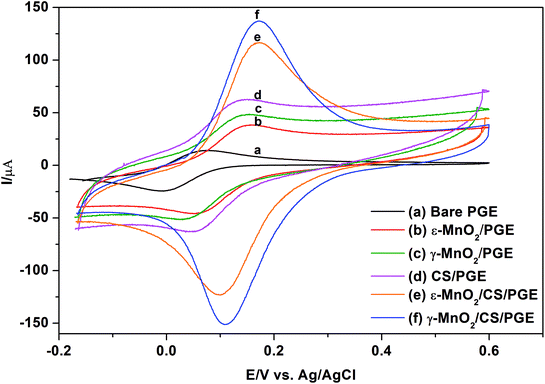
Although immersing PGE in MnO2 NPs suspended in THF gives approximately four-fold improvement in the peak current of K3[Fe(CN)6] compared to bare PGE, it was the idea to furthermore use a binder which might beneficially permit efficient sticking of MnO2 NPs to the electrode surface and accordingly increase peak current due to synergistic electrocatalytic effect of both. Bare PGE was suspended for 30 min in 0.5% chitosan polymer, which is used as a binder. After air drying for 5 min, chitosan-modified PGE (CS/PGE) was dipped in MnO2 NP suspension in THF for one hour. As presented in Fig. 7, the strong adsorptive property of chitosan is revealed by the significant decrease in the concentration of the suspended MnO2 NPs after one hour of immersing CS/PGE in MnO2 NP suspension in THF (fading in the black colour of the original suspension). Here, it should be emphasized that the positive charge on the surface of chitosan (pKa of amino group of chitosan ∼6.3)39 adds an additional advantage because it attracts negatively charged OH− present on MnO2 NP surface and consequently permits efficient attachment of suspended MnO2 NPs on CS/PGE. This efficiency manifests itself by a considerable increase in the oxidation/reduction peak currents of K3[Fe(CN)6] when using MnO2/CS/PGE (γ or ε forms) if compared to (1) bare PGE, (2) CS/PGE or (3) MnO2/PGE (Fig. 8). Although γ-form gives higher signal than ε-form, the difference between the two forms is small, which proves the usefulness of both forms in electrochemical applications.Immersing the bare PGE in MnO2 NPs suspended in chitosan solution or dipping bare PGE in chitosan solution then in MnO2 NP suspension in water results in very low peak currents, which can be explained on the basis that very polar protic solvents such as water in addition to hydrogen bond formation with surface OH− on MnO2 NPs, can neutralize or stabilize the charge on the surface hydroxyl via H+ obtained from water dissociation and deactivate the oxidation capability of MnO2 NPs. This leads to inefficient attachment of NPs to chitosan-modified PGE and might result in deactivation of active adsorption sites, making MnO2 less accessible to analytes. Recently, Huang et al.16 utilized ε-MnO2 microspheres together with chitosan-modified GCE in the determination of Ponceau 4R, a synthetic colorant. The major difference between the current study and the previously reported one16 is that chitosan is used to immobilize ε-MnO2 microspheres; however, no additional or synergistic effect of chitosan on the peak current was described. In addition, ε-MnO2 microspheres were dispersed into chitosan solution directly; nevertheless no deactivation consequence for ε-MnO2 microspheres was observed.
3.6. SEM characterization of bare and modified PGE
A comparison between morphological characteristics of bare and modified PGE was carried out using SEM. The top-view SEM images for the bare and modified electrodes after drying and before the electrochemical experiments are shown in Fig. 9. Fig. 9a indicates the surface morphology of the bare PGE, which shows that graphite flakes are fragile, flat with large pores. After modification of PGE with either γ-form (Fig. 9b) or ε-form (Fig. 9c) of MnO2 NPs, it is clear that NPs cover completely the PGE surface and fill the gaps between the graphite layers. Moreover, their appearance indicates that they are slightly swollen due to the influence of THF on NPs. The surface of the PGE attains a shiny appearance due to complete coverage of its surface with MnO2 NPs. After modification of PGE with chitosan polymer (Fig. 9d), it is clear that major parts of PGE become invisible due to immobilization of chitosan polymer on the electrode surface. On the other hand, it is obvious that γ-form (Fig. 9e) or ε-form (Fig. 9f) of MnO2 NPs are well distributed within chitosan polymer and show a great surface coverage for CS/PGE. The difference in the surface morphology of the bare and modified PGE electrodes reflects its influence by the synergistic increase in the oxidation/reduction peak current of [Fe(CN)6]3− when using MnO2/CS/PGE (γ or ε forms) if compared to (1) bare PGE, (2) CS/PGE or (3) MnO2/PGE (Fig. 8). The obtained results highlight the importance of both electrocatalytic activity of MnO2 NPs and electrostatic interaction provided by chitosan polymer in the significant improvement of the oxidation/reduction peak current of [Fe(CN)6]3−.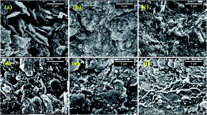 | ||
| Fig. 9 SEM images of (a) bare PGE; (b) γ-MnO2/PGE; (c) ε-MnO2/PGE; (d) CS/PGE; (e) γ-MnO2/CS/PGE; and (f) ε-MnO2/CS/PGE. | ||
For further confirmation of the importance of THF as a suspending solvent for MnO2 NPs, the surface morphology of PGE, immersed in γ-MnO2 NPs suspension in water for one hour and dried before the electrochemical experiment, was examined. As shown in Fig. 10, significant parts of PGE were not covered with γ-MnO2 NPs exposing the black surface of the bare PGE (cf. Fig. 9b). This result greatly supports the idea that water cannot be employed as a suspending solvent for MnO2 NPs due to either inefficient attachment of MnO2 NPs to the electrode surface or the negative impact of water on the electrocatalytic activity of MnO2 NPs.
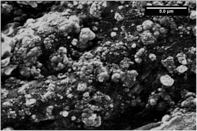 | ||
| Fig. 10 SEM image of γ-MnO2/PGE after immersing bare PGE for one hour in γ-MnO2 NPs suspended in water. | ||
3.7. Comparison between electrochemical activities of modified electrodes by electron-transfer kinetics
Electrochemical properties of the modified electrodes were studied using [Fe(CN)6]3− by the cyclic voltammetric technique (Fig. 8). The cyclic voltammograms of 1.0 mmol L−1 [Fe(CN)6]3− in 0.1 mol L−1 KCl were recorded at a scan rate of 100 mV s−1 using bare PGE (Fig. 8a), chitosan-modified PGE (Fig. 8d), γ-MnO2-modified PGE (Fig. 8c), ε-MnO2-modified PGE (Fig. 8b), γ-MnO2/chitosan-modified PGE (Fig. 8f) and ε-MnO2/chitosan-modified PGE (Fig. 8e). The peak separation values (ΔEp) are indicated in Table 3. The ΔEp value is considered as an indication for electron transfer rate, as the smaller the ΔEp value, the higher the electron transfer rate. Using bare PGE (Fig. 8a), the ΔEp value is significantly large and the peak is weak and broad. On modification of the surface of bare PGE with γ- or ε-MnO2 NPs, the peak becomes sharper with higher current intensity and moderately low ΔEp values. On modifying the bare PGE surface with chitosan binder alone, the sensitivity is enhanced by 4 times; nevertheless the change in the ΔEp value was not significant when compared to that of bare PGE. Therefore, chitosan as a binder and MnO2 NPs as electrode modifier were used simultaneously to enhance the electrocatalytic activity and the electron transfer rate of the electrode. Upon adsorption of MnO2 NPs on the chitosan-modified PGE, the sensitivity was enhanced by about 3 times if compared to that obtained when using MnO2 NPs in the absence of chitosan binder. In addition, the presence of γ- or ε-MnO2 NPs improves the electron transfer rate as indicated by the low ΔEp values. The calculated peak voltage separation between the oxidation and reduction peaks for the two types of MnO2/chitosan-modified PGE was equal to or slightly higher than the theoretical value (ΔEp = 0.059/n, where n = 1) indicating the perfect reversibility of these electrodes, while the other types of electrodes give higher ΔEp values that implies the quasi-reversible behavior of these electrodes.| Electrodes | CV anodic current (μA) of 1.0 mmol L−1 [Fe(CN)6]3− | Peak separation (ΔEp, mV) | Aeff (mm2) | Charge transfer resistance (Rct, Ω) |
|---|---|---|---|---|
| Bare PGE | 14.1 | 101.00 | 12.1 | 112.2 |
| ε-MnO2/PGE | 38.6 | 72.99 | 26.7 | 39.4 |
| γ-MnO2/PGE | 48.4 | 79.13 | 35.3 | 33.9 |
| CS/PGE | 69.5 | 96.61 | 34.8 | 30.4 |
| ε-MnO2/CS/PGE | 116.7 | 59.19 | 104.0 | 22.27 |
| γ-MnO2/CS/PGE | 132.4 | 61.34 | 105.0 | 16.97 |
In order to confirm this explanation, the effective surface area (Aeff) of each electrode was calculated using the Randles–Sevcik equation:65
| Ip = 2.69 ×10⁵ n3/2AeffD1/2υ1/2C | (2) |
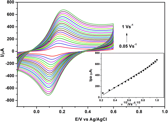 | ||
| Fig. 11 Cyclic voltammograms of 1.0 mmol L−1 K3[Fe(CN)6] in 0.1 mol L−1 KCl obtained at different scan rates using γ-MnO2/CS/PGE. Accumulation time, 60 s. | ||
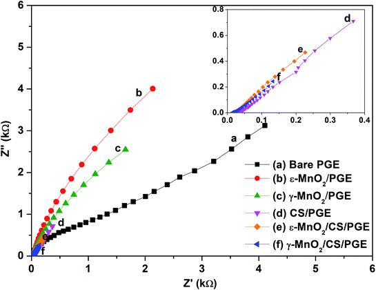
EIS as a non-destructive technique was used to study the interfacial properties of the electrode and solution. EIS measurements were performed in 1.0 mmol L−1 K3[Fe(CN)6] in 0.5 mol L−1 KCl adjusted to pH 2.5 with 1.0 mol L−1 HCl. The measurements were performed at a potential amplitude of 10 mV and in the frequency range of 1.0 Hz to 10 kHz. From the results of EIS, charge transfer resistance (Rct) can be calculated with the aid of Zview software (Zview version 3.1c). Charge transfer resistance (Rct) calculated here is an important parameter of electron transfer across the electrode interface. Therefore, the lower Rct value of γ-MnO2/CS/PGE indicates the maximum catalytic activity of the modified electrode and highest electro-conductivity if compared to bare PGE and the other modified electrodes. Electrochemical impedance spectra of modified and unmodified PGEs are shown in Fig. 12.
The Nyquist plots of ε-MnO2/CS/PGE and γ-MnO2/CS/PGE or ε-MnO2/PGE and γ-MnO2/PGE exhibit only linear plots relevant to a more diffusion-like behavior, while that for bare PGE or CS/PGE exhibits a linear plot with a slight circular part. This behavior in the presence and absence of MnO2 NPs implies that the charge-transfer process is highly correlated to MnO2 NPs. This slowness in electron transfer was due to the high resistance that explains the appearance of the circular part in the plot of bare PGE or CS/PGE if compared with the other electrodes. Although CS/PGE is less than ε-MnO2/PGE and γ-MnO2/PGE in terms of resistance, nevertheless the small circular part indicates the slow transfer to some extent. The fitted values of Rct for bare PGE, ε-MnO2/PGE, γ-MnO2/PGE, CS/PGE, ε-MnO2/CS/PGE and γ-MnO2/CS/PGE were calculated and shown in Table 3. The obtained results confirm that the fabricated γ-MnO2 NPs coating on chitosan-modified PGE enhances the electron transfer and diminishes the resistance across the electrode–solution interface.
3.8. Selectivity of γ-MnO2/CS/PGE for negatively charged compounds
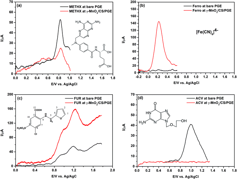
Four different model compounds were selected to carry out this study. Their chemical structures are presented in Fig. 13. The selected compounds have differences in their acidic/basic characters and hence differences in their protonation/deprotonation states. The tested compounds are: methotrexate (METHX), ferrocyanide (Ferro), furosemide (FUR) and acyclovir (ACV). The pH used to perform this investigation (after carrying out preliminary trials) is the optimum or near optimum for oxidation each compound. Here, it is the target to confirm the assumption that the positively charged γ-MnO2/CS/PGE at the studied pH values is selective only for negatively charged compounds.METHX is an antitumor drug with two acidic groups (pKa1 = 3.4 and pKa2 = 4.7) and one basic group (pKa3 = 5.7).66 At pH 3, this compound possesses partial negative and full positive charges (zwitterionic), which correspond to the dissociation of α-carboxyl group (pKa1 = 3.4) and N(1) of the pteridine ring (pKa3 = 5.7). As shown in Fig. 13a, the peak current using bare PGE is higher than that obtained using γ-MnO2/CS/PGE. By increasing the pH value to 5, which corresponds to full dissociation of α-carboxyl group (pKa1 = 3.4) and partial dissociation of γ-carboxyl group (pKa2 = 4.7), an increase of the peak current of METHX using γ-MnO2/CS/PGE was observed; however, it is still lower than that obtained using bare PGE due to partial positive charge of METHX (results not shown). On the other hand, the peak current of Ferro (at pH 2.2), which is an anticaking agent used in table salt, is greatly enhanced in the presence of γ-MnO2/CS/PGE (Fig. 13b) due to electrostatic interaction between negative charge of Ferro and positive charge of chitosan together with the complexation effect with chitosan.67
The same observation holds true for FUR, which is a potent antidiuretic with a pKa = 3.6 (for carboxylic acid moiety).54 The partial negative charge of FUR at pH 3 (optimum pH for oxidation of FUR) permits efficient interaction with positively charged γ-MnO2/CS/PGE as reflected by Fig. 13c. A shift of acid dissociation constant of FUR to lower values in the presence of chitosan is possible, which permits higher degree of dissociation and more attraction to the electrode surface.
Finally, ACV, an antiviral drug (pKa1 (basic) = 2.27 and pKa2 (acidic) = 9.25),68 has a positive charge in 0.1 mol L−1 H2SO4. No peak is observed at all using γ-MnO2/CS/PGE due to electrostatic repulsion (Fig. 13d).
3.9. Application of the modified electrode for determination of the diuretic drug FUR
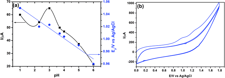
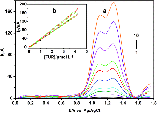
It was found that the highest peak current was obtained at pH 3.0. It can be clearly observed that the peak current and potential for the oxidation of FUR are closely related to the pH value of the supporting electrolyte. It was found that the oxidation peak potential of FUR shifted toward less positive potential values with increasing pH (Fig. 14a). Based on the results obtained, over the studied pH range, a linear relationship was obtained between EP and pH, which can be expressed by the following equation: EP (V) = 1.0621–0.0155 pH (r = 0.9269). This supporting electrolyte (pH 3.0) was chosen with respect to sharp response and better peak shape for the construction of calibration curve and for determination of FUR in its standard solution and in pharmaceutical and biological samples. Based on the voltammetric experimental results reported by Malode et al.56 and Semaan et al.,54 it was found that the number of electrons transferred (n) equals two; therefore we have two rate-limiting steps in the electro-oxidation of FUR (Fig. 13c). They suggested that the reaction occurred at the amine position attached to C6, which will initially give rise to a cation radical with loss of one proton and one electron. The 1st limiting step must then be immediately followed by loss of a second electron and of a proton (2nd limiting step) with the formation of 2-chloro-4-[(furan-2-lymethylene)amino]benzenesulfonamide.56
The effects of accumulation potential (Eacc) and time (tacc) on the stripping peak currents of 15.0 μmol L−1 FUR were also studied. The accumulation potential (Eacc) was studied over the potential range of −0.4 to 0.4 V. The results showed that the peak currents increased with changing potential until 0.0 V potential, then decreased again gradually. Hence 0.0 V was selected as an optimum potential for the determination of FUR. With regard to the accumulation time (tacc), it was observed that the optimum time is 240 s and thereafter no further increase in the current signal was obtained due to the blockage of the electrode surface by the products of oxidation of FUR. Thus, 240 s was chosen as the optimum accumulation time for oxidation of FUR.
The operational voltammetric parameters were optimized as well by measuring the peak current against these parameters including pulse height, step height and frequency. SW voltammograms of 15.0 μmol L−1 FUR in BR buffer of pH 3.0 using γ-MnO2/CS/PGE were recorded for various pulse parameters (frequency in the range of 10–250 Hz; pulse height in the range of 5–30 mV; and step height in the range of 5–25 mV). The best developed voltammetric peak was obtained using the following parameters: frequency = 250 Hz, pulse height = 20 mV and step height = 10 mV, which were chosen for the rest of the study.
a Limit of detection.b Limit of quantitation.c Standard deviation of the intercept.d Standard deviation of the slope.e Confidence interval calculated at P = 0.95.f Sum of square errors.g Residual standard deviation (standard error of estimate (SEE).h Method standard deviation (=Syx/b).i Relative standard deviation of the method (=Sx0/![[x with combining macron]](https://www.rsc.org/images/entities/i_char_0078_0304.gif) ).j n is the number of experiments and RSD is the relative standard deviation. ).j n is the number of experiments and RSD is the relative standard deviation. |
||
|---|---|---|
| Parameter | Peak I | Peak II |
| Linearity range (μmol L−1) | 0.05–4.20 | 0.05–4.20 |
| LOD (nmol L−1)a | 4.44 (1.47 ng mL−1) | 3.88 (1.28 ng mL−1) |
| LOQ (nmol L−1)b | 13.46 | 11.77 |
| Intercept, a (μA) ± SDc | −2.340 ± 0.765 | −3.972 ± 1.527 |
| Slope, b (μA μmol−1 L) ± SDd | 37.134 ± 0.370 | 42.469 ± 0.739 |
| Confidence interval of (a)e | ±1.763 | ±3.522 |
| Confidence interval of (b)e | ±0.853 | ±1.704 |
| SSEf | 19.957 | 79.637 |
| Syxg | 1.579 | 3.155 |
| Sx0 (μmol L−1)h | 0.043 | 0.074 |
| Sr%i | 2.75 | 4.73 |
| Correlation coefficient (r) | 0.9996 | 0.9988 |
| Determination coefficient (r2) | 0.9992 | 0.9976 |
| Intra-day precision (n = 8) RSD (%)j for 2.0 μmol L−1 FUR | 2.53 | 2.70 |
| Inter-day precision, 5 days, n = 40 (%) for 2.0 μmol L−1 FUR | 3.72 | 4.15 |
| Electrode | LOD (nmol L−1) | Ref. |
|---|---|---|
| Carboxyl-MWCNT sensor | 21.20 | 59 |
| Gold electrode | 41.20 | 55 |
| Glassy carbon electrode | 151.00 | 53 |
| Multi-walled carbon nanotube paste electrode | 290.00 | 56 |
| Graphite–polyurethane composite electrode | 150.00 | 54 |
| Carbon paste electrode | 4.70 | 58 |
| Graphene oxide-modified glassy carbon electrode | 110.00 | 57 |
| γ-MnO2/chitosan-modified PGE | 3.88 | Present work |
The applicability of the proposed method for the determination of FUR in biological fluid taking human urine as an example was attempted. FUR is a potent diuretic which, if given in excessive amounts, can lead to a profound diuresis with water. It is detectible in urine within 24 h following injection.41,42 Drug-free human urine samples, obtained from five healthy volunteers, were centrifuged and filtered through 0.45 μm membrane filter and stored frozen until the assay. Urine samples were diluted 10 times with BR buffer before taking the measurements, without further pretreatment and no additional peaks were obtained for oxidation of any substance that might be present in the urine samples. Then urine samples were spiked with different amounts of FUR standard and the developed SWV method was applied. The recoveries from urine were measured by spiking drug-free urine with known amounts of FUR, and then the % recoveries were calculated by comparison with the same concentrations in the standard curve. The results of four urine samples are listed in Table 7. The recovery determined was in the range from 98.72% to 99.43% and the SD was not more than 1.89. Good recoveries of FUR were achieved from these matrices, indicating that application of the proposed method to the analysis of FUR in biological fluid could be easily assessed.
3.10. Interference studies
To determine the selectivity of the proposed method for the determination of FUR, the influence of potentially interfering substances on its determination was investigated using the SWV method at the γ-MnO2/chitosan-modified PGE. The tolerance limit for interfering species was considered as the maximum concentration of foreign substances that caused a relative error less than 5% for determination of 15.0 μmol L−1 FUR under the optimum conditions. For 15.0 μmol L−1 FUR, the results showed that over 100-fold excess of ascorbic acid, uric acid, guanine derivatives, glucose, citric acid and some metals such as Cu2+ and Pb2+ did not interfere with the FUR response. The oxidation peaks for these metals were observed at different potentials, which are 0.05 V for Cu2+ and −0.2 V for Pb2+ at initial potential of −0.6 and −0.8 V for Cu2+ and Pb2+, respectively. The results obtained show recoveries in the range from 95.6 to 102.3% for 15.0 μmol L−1 FUR solution, indicating that there was no matrix interference with FUR by the proposed SWV method using the γ-MnO2/chitosan-modified PGE. These results indicate the high selectivity of the fabricated sensor for negatively charged compounds such as FUR.3.11. Stability of the electrode
The SWV curve of 15.0 μmol L−1 of FUR was daily recorded to test the stability of the newly modified electrode after its preservation in THF. It was found that it is highly stable even after 7 days and the peak retained 96.7% of its initial reading with a standard deviation of 1.76. This shows the high stability of the γ-MnO2/chitosan-modified PGE.4. Conclusions
In the current work, a novel method was developed for the synthesis of two MnO2 polymorphs (ε and γ) from the comproportionation reaction of KMnO4 and MnCl2 depending on reaction temperature. ε- and γ-MnO2 NPs were used for fabrication of a novel, sensitive and selective electrosensor that was applied for determination of FUR in different pharmaceutical and biological samples. Chitosan as a binder improves the adsorption of MnO2 NPs on the surface of the electrode. The suspending solvent of the MnO2 NPs has a great influence on the activation and adsorption of MnO2 NPs. THF was the best suspending solvent, resulting in high sensitivity and selectivity. The developed modified electrode exhibits a remarkable increase in peak current and fast electron transfer reaction for the electro-oxidation process of FUR. The SWV current increased linearly while increasing the concentration of FUR from 0.05 to 4.20 μmol L−1 with low detection limit of 4.44 nmol L−1 (1.47 ng mL−1) and 3.88 nmol L−1 (1.28 ng mL−1) respectively for the two peaks. High selectivity and low detection limit promote the use of the proposed method in the determination of FUR in its ampoule form and in human urine as a biological sample without any effect from interfering matrices. The utility of the developed method can be further expanded to other negatively charged compounds of pharmaceutical, environmental or biological interest.Conflicts of interest
There are no conflicts of interest to declare.References
- M. L. Yola and N. Atar, Electrochim. Acta, 2014, 119, 24–31 CrossRef.
- H. Karimi-Maleh, F. Tahernejad-Javazmi, N. Atar, M. L. Yola, V. K. Gupta and A. A. Ensafi, Ind. Eng. Chem. Res., 2015, 54, 3634–3639 CrossRef.
- S. K. Srivastava, V. K. Gupta and S. Jain, Analyst, 1995, 120, 495–498 RSC.
- M. L. Yola, T. Eren and N. Atar, Electrochim. Acta, 2014, 125, 38–47 CrossRef.
- C. Gode, M. L. Yola, A. Yilmaz, N. Atar and S. Wang, J. Colloid Interface Sci., 2017, 508, 525–531 CrossRef PubMed.
- M. Beytur, F. Kardas, O. Akyildirim, A. Ozkan, B. Bankoglu, H. Yuksek, M. L. Yola and N. Atar, J. Mol. Liq., 2018, 251, 212–217 CrossRef.
- S. Mert, B. Bankoglu, A. Ozkan, N. Atar and M. L. Yola, J. Mol. Liq., 2018, 254, 8–11 CrossRef.
- M. L. Yola, V. K. Gupta and N. Atar, Mater. Sci. Eng., C, 2016, 61, 368–375 CrossRef PubMed.
- M. L. Yola, T. Eren and N. Atar, J. Electrochem. Soc., 2016, 163, B588–B593 CrossRef.
- M. L. Yola and N. Atar, Ind. Eng. Chem. Res., 2017, 56, 7631–7639 CrossRef.
- S. Salmanpour, A. Sadrnia, F. Karimi, N. Majani, M. L. Yola and V. K. Gupta, J. Mol. Liq., 2018, 254, 255–259 CrossRef.
- M. L. Yola, V. K. Gupta, T. Eren, A. E. Sen and N. Atar, Electrochim. Acta, 2014, 120, 204–211 CrossRef.
- D. Manoj, R. Saravanan, J. Santhanalakshmi, S. Agarwal, V. K. Gupta and R. Boukherroub, Sens. Actuators, B, 2018, 266, 873–882 CrossRef.
- B. Hayati, A. Maleki, F. Najafi, F. Gharibi, G. McKay, V. K. Gupta, S. Harikaranahalli Puttaiah and N. Marzban, Chem. Eng. J., 2018, 346, 258–270 CrossRef.
- S. L. Suib, J. Mater. Chem., 2008, 18, 1623–1631 RSC.
- J. Huang, Q. Zeng and L. Wang, Electrochim. Acta, 2016, 206, 176–183 CrossRef.
- Y. H. Bai, J. J. Xu and H. Y. Chen, Biosens. Bioelectron., 2009, 24, 2985–2990 CrossRef PubMed.
- A. Salimi, B. Pourbahram, S. Mansouri-Majd and R. Hallaj, Electrochim. Acta, 2015, 156, 207–215 CrossRef.
- S. MansouriMajd, H. Teymourian, A. Salimi and R. Hallaj, Electrochim. Acta, 2013, 108, 707–716 CrossRef.
- S. C. Sultan, P. Kara, U. Anik and M. Ozsoz, RSC Adv., 2014, 4, 39691–39696 RSC.
- C. Serdar, A. Oguz and A. Ulkü, Food Anal. Methods, 2016, 9, 500–504 CrossRef.
- K. Schachl, H. Alemu, K. Kalcher, J. Jezkova, I. Svancara and K. Vytras, Analyst, 1997, 122, 985–989 RSC.
- E. Mehmeti, D. M. Stankovic, S. Chaiyo, L. Svorc and K. Kalcher, Microchim. Acta, 2016, 183, 1619–1624 CrossRef PubMed.
- A. M. Bystrom, Acta Chem. Scand., 1949, 3, 163–173 CrossRef.
- P. M. de Wolff, Acta Crystallogr., 1959, 12, 341–345 CrossRef.
- Y. Chabre and J. Pannetier, Prog. Solid State Chem., 1995, 23, 1–130 CrossRef.
- P. Ruetschi, J. Electrochem. Soc., 1984, 131, 2737–2744 CrossRef.
- P. Ruetschi, J. Electrochem. Soc., 1988, 135, 2657–2663 CrossRef.
- P. Ruetschi and R. Giovanoli, J. Electrochem. Soc., 1988, 135, 2663–2669 CrossRef.
- J. B. Arnott, R. P. Williams, A. G. Pandolfo and S. W. Donne, J. Power Sources, 2007, 165, 581–590 CrossRef.
- M. Akanda, M. Sohail, M. Aziz and A. N. Kawde, Electroanalysis, 2016, 28, 408–424 CrossRef.
- J. Wang, A. N. Kawde and E. Sahlin, Analyst, 2000, 125, 5–7 RSC.
- A. J. Fatiadi, The oxidation of organic compounds by active manganese dioxide, in Organic Syntheses by Oxidation with Metal Compounds, ed. W. J. Mijs and C. R. H. I. de Jonge, Plenum Press, New York, 1986, pp. 119–260 Search PubMed.
- G. Cahiez and M. Alami, Manganese Dioxide, in Handbook of Reagents for Organic Synthesis: Oxidizing and Reducing Agents, ed. S. D. Burke and R. L. Danheiser, John Wiley & Sons, New York, 1999, pp. 231–236 Search PubMed.
- G. Cahiez and M. Alami, Manganese Dioxide, in Encyclopedia of Reagents for Organic Synthesis, John Wiley & Sons, Ltd, 2004 Search PubMed.
- J. Barek, A. Muck, J. Wang and J. Zima, Sensors, 2004, 4, 47–57 CrossRef.
- F. Kuralay, T. Vural, C. Bayram, E. B. Denkbas and S. Abaci, Colloids Surf., B, 2011, 87, 18–22 CrossRef PubMed.
- Y. Liu, X. Qu, H. Guo, H. Chen, B. Liu and S. Dong, Biosens. Bioelectron., 2006, 21, 2195–2201 CrossRef PubMed.
- Y. C. Tsai, S. Y. Chen and H. W. Liaw, Sens. Actuators, B, 2007, 125, 474–481 CrossRef.
- X. Kang, Z. Mai, X. Zou, P. Cai and J. Mo, Anal. Biochem., 2007, 369, 71–79 CrossRef PubMed.
- Furosemide, https://www.drugs.com/ppa/furosemide.html, (accessed 27.01.2018).
- L. L. Boles Ponto and R. D. Schoenwald, Clin. Pharmacokinet., 1990, 18, 381–408 CrossRef.
- M. Espinosa Bosch, A. J. Ruiz Sanchez, F. Sanchez Rojas and C. Bosch Ojeda, J. Pharm. Biomed. Anal., 2008, 48, 519–532 CrossRef PubMed.
- T. Bansal, M. Singh, G. Mishra, S. Talegaonkar, R. K. Khar, M. Jaggi and R. Mukherjee, J. Chromatogr. B: Anal. Technol. Biomed. Life Sci., 2007, 859, 261–266 CrossRef PubMed.
- S. Chawla, S. Ghosh, V. Sihorkar, R. Nellore, T. R. S. Kumar and N. R. Srinivas, Biomed. Chromatogr., 2006, 20, 349–357 CrossRef PubMed.
- S. Carda-Broch, M. C. Garcia-Alvarez-Coque, E. F. Simo-Alfonso and J. S. Esteve-Romero, Anal. Chim. Acta, 1997, 353, 215–226 CrossRef.
- D. I. Sora, S. Udrescu, F. Albu, V. David and A. Medvedovici, J. Pharm. Biomed. Anal., 2010, 52, 734–740 CrossRef PubMed.
- J. Caslavska and W. Thormann, J. Chromatogr. B: Anal. Technol. Biomed. Life Sci., 2002, 770, 207–216 CrossRef.
- F. Silva Semaan and E. T. G. Cavalheiro, Anal. Lett., 2006, 39, 2557–2567 CrossRef.
- M. S. Garcia, C. Sanchez-Pedreno, M. I. Albero and V. Rodenas, J. Pharm. Biomed. Anal., 1997, 15, 453–459 CrossRef PubMed.
- C. M. Peralta, L. P. Fernandez and A. N. Masi, Anal. Chim. Acta, 2010, 661, 85–90 CrossRef PubMed.
- M. L. Luis, J. M. G. Fraga, A. I. Jimenez, F. Jimenez, O. Hernandez and J. J. Arias, Talanta, 2004, 62, 307–316 CrossRef PubMed.
- M. B. Barroso, R. M. Alonso and R. M. Jimenez, Anal. Chim. Acta, 1995, 305, 332–339 CrossRef.
- F. S. Semaan, E. M. Pinto, E. T. Cavalheiro and C. M. Brett, Electroanalysis, 2008, 20, 2287–2293 CrossRef.
- N. P. Shetti, L. V. Sampangi, R. N. Hegde and S. T. Nandibewoor, Int. J. Electrochem. Sci., 2009, 4, 104–121 Search PubMed.
- S. J. Malode, J. C. Abbar, N. P. Shetti and S. T. Nandibewoor, Electrochim. Acta, 2012, 60, 95–101 CrossRef.
- M. Hasanzadeh, M. H. Pournaghi-Azar, N. Shadjou and A. Jouyban, RSC Adv., 2014, 4, 6580–6590 RSC.
- S. D. Bukkitgar and N. P. Shetti, Cogent Chem., 2016, 2, 1152784 CrossRef.
- R. Heidarimoghadam and A. Farmany, Mater. Sci. Eng., C, 2016, 58, 1242–1245 CrossRef PubMed.
- C. M. Julien, M. Massot and C. Poinsignon, Spectrochim. Acta, Part A, 2004, 60A, 689–700 CrossRef.
- M. V. Ananth, S. Pethkar and K. Dakshinamurthi, J. Power Sources, 1998, 75, 278–282 CrossRef.
- M. Abdul Aziz and A. N. Kawde, Talanta, 2013, 115, 214–221 CrossRef PubMed.
- C. Reichardt and T. Welton, Appendix A. Properties, Purification, and Use of Organic Solvents, Solvents and Solvent Effects in Organic Chemistry, Wiley-VCH Verlag GmbH & Co. KGaA, 2010, pp. 549–586 Search PubMed.
- H. Chen, P. K. Chu, J. He, T. Hu and M. Yang, J. Colloid Interface Sci., 2011, 359, 68–74 CrossRef PubMed.
- Electrochemical Methods: Fundamentals and Applications, ed. A. J. Bard and L. R. Faulkner, Wiley & Sons, 2000 Search PubMed.
- K. Mioduszewska, J. Dolzonek, D. Wyrzykowski, L. Kubik, P. Wiczling, C. Sikorska, M. Tonski, Z. Kaczynski, P. Stepnowski and A. Bialk-Bielinska, Trends Anal. Chem., 2017, 97, 283–296 CrossRef.
- C. A. Rodrigues, E. Stadler, M. C. M. Laranjeira and V. Drago, J. Braz. Chem. Soc., 1997, 8, 07–11 Search PubMed.
- Acyclovir. https://www.drugbank.ca/drugs/DB00787 (accessed 27/1/2018).
- Challenges in Analytical Quality Assurance, ed. M. Reichenbaecher and J. W. Einax, Springer-Verlag, Berlin Heidelberg, 2011 Search PubMed.
- ICH Harmonised Tripartite Guidelines, Validation of analytical procedures: text and methodology Q2(R1), http://www.ich.org/products/guidelines/quality/article/quality-guidelines.html, (accessed 27.01.2018).
| This journal is © The Royal Society of Chemistry 2018 |

