 Open Access Article
Insight into the dispersion behavior of 1-butyl-3-methylimiazolium chloride confined in nanoscale pores of carbon materials†
Shuxia Di ,
Yiqi Xu,
Qunfeng Zhang,
Xiaolong Xu,
Yuanyuan Zhai,
Bolin Wang,
Haihua He,
Qingtao Wang
 ,
Hao Xu,
Yishu Jiang,
Jia Zhao
 and
Xiaonian Li*
Industrial Catalysis Institute, Laboratory Breeding Base of Green Chemistry-Synthesis Technology, Zhejiang University of Technology, Hangzhou 310014, China. E-mail: jiazhao@zjut.edu.cn; xnli@zjut.edu.cn; Fax: +86 57188320002; Tel: +86 57188320002
First published on 2nd July 2018
Abstract
It is important to understand the behaviour of ionic liquids (ILs) in nanoscale pores, as application of supported ionic liquid phase (SILP) materials has attracted much attention. The main intention of this investigation is to study the dispersion performance of ionic liquid on activated carbons with different surface oxygen groups. Several active carbons with diverse oxygenated surface groups were obtained by oxidation and reduction methods. All samples were impregnated with [Bmim]Cl at different loadings. The blocked porosity of ionic liquid on SILP materials mainly depends on the amount of ionic liquid and surface oxygen content. In addition, stability of the supported IL in water was tested by analyzing the leached amount of IL. We found that the supported IL is not easily leached from the interface of carbon with low amount of surface oxygen. This may be due to the high free π-electron density of oxygen-free supports, forming more CH–π bonds with H atoms at the C2 position of the acidic cation. In addition, we propose that dispersion of ionic liquid in the pores depends on the density of surface free π-electrons of carbon materials.
1 Introduction
Ionic liquids possess an array of unique physicochemical properties, namely, negligible vapor pressure, relatively low viscosity, effective non-volatility, thermal stability, and relatively high ionic conductivity,1–3 and have strongly attracted scientific attention. They are considered as promising green solvents to replace conventional volatile organic compounds. A variety of new valuable applications of ILs have continuously been developed in some industries, such as gas separation,4–7 catalysts,8–10 extractants,11,12 materials synthesis,13,14 explosives and propellant fuels.15 In some cases, it is necessary to immobilize ionic liquids on porous materials, which disperses the ionic liquids on the inter-surfaces of the porous structure and at the same time, allows the retention of high specific surface areas and structural properties. In particular to the catalysis field, such as in acetylene hydrochlorination reaction,16,17 the introduction of ionic liquids promotes both catalytic activity and stability of the catalysts. Therefore, it is of great value to investigate the dispersion behavior of ionic liquids as they play a key role in the SILC system, particularly in gas–solid reactions.To our knowledge, ionic liquids can be easily supported on porous materials, forming functionalized materials with a “thin film”, which has made SILP systems a topic of intensive scientific research. For example, Li et al.16 proposed that the weak van der Waals interaction between imidazolium-based ionic liquid and single-walled carbon nanotubes (SWCNTs) dispersed the SWCNTs into the IL. Rodriguez et al.17 found that the IL tends to fill micropores first, then mesopores and finally macropores in SILP systems. Szesni et al.18 studied the distribution of IL immobilized onto silica gel using solid-state NMR characterization, presenting optimum ionic liquid loading. Stark et al.19 studied the solid-ionic liquid interfaces between IL and ordered or disordered mesoporous silica; they proposed that the formation of layer or droplet depended on the physicochemical properties of the ionic liquid. To the best of our knowledge, only the stability (immobilization and thermal stability) of immobilized ionic liquids has so far been reported,20 but almost no group has analyzed the relationship between IL and carbon materials in detail due to the complexity of surface chemicals and random porosity of the carbon materials. The relation of dispersion behavior of ionic liquid confined in nanoscale pores of carbon materials to the surface chemical properties is still an open question.
In the present study, a series of carbon materials with different surface chemical functional groups were investigated. Also, the dispersion behavior of ionic liquid supported on carbon materials was analyzed via a variety of characterization methods. We discovered that the surface free π-electron density of porous carbon materials not only enhanced the distribution of ionic liquid on the surface of porous carbons materials, but also contributed to immobilizing the ionic liquid on the support due to the formation of CH–π bond with H atom at the C2 position of the acidic cation.
2 Experimental
2.1 Preparation of SILP materials
Columnar activated carbon NORIT ROX 0.8 with diameter of 0.8 mm and length of 5 mm was chosen as the support, which contains almost no surface oxygen groups. In order to investigate effects of surface oxygen groups on distribution behavior of ionic liquid on the surface of activated carbon, the original carbon material was treated with concentrated nitric acid, followed by thermal treatment.Specifically, the surface oxygen groups on activated carbon were introduced by dipping the activated carbon into concentrated nitric acid (65 wt%) at room temperature for 12 h. Then, the activated carbon was filtered and rinsed with deionized water until the pH value of the filtrate was about 7. Eventually, the treated activated carbon was dried at 120 °C under vacuum for 12 h and labelled as AC-n. Next, the as-prepared AC-n was thermally treated at 500 °C or 900 °C for 4 h in N2 atmosphere, with a heating rate of 10 °C min−1, and the obtained samples were denoted as AC-n-N500 and AC-n-N900, respectively.
In this study, the SILP materials were prepared from the treated activated carbon by loading different amounts of 1-butyl-3-methylimiazolium chloride ([Bmim]Cl). The SILP materials with different IL loadings of 10 wt%, 20 wt% and 40 wt% were treated in vacuum environment, so that the entire impregnation solution could be adsorbed into the pores of the supports. Then, the materials were dried at 120 °C under vacuum for 12 h to remove water. The obtained SILP materials were labeled as AC-n-10 wt%, AC-n-20 wt%, AC-n-40 wt%, AC-n-N500-10 wt%, AC-n-N500-20 wt%, AC-n-N500-40 wt%, AC-n-N900-10 wt%, AC-n-N900-20 wt%, and AC-n-N900-40 wt%, according to preparation method.
2.2 Characterization of SILP materials
The types and amounts of oxygenated surface groups on activated carbon were determined by CO- and CO2-temperature-programmed desorption (TPD) using automated AMI-200 equipment (Altamira Instruments). The sample (100 mg) was placed in a quartz tube and heated from 30 °C to 900 °C at a heating rate of 5 °C min−1 under helium flow (30 mL min−1). CO and CO2 signals were monitored by a quadrupole mass spectrometer. TPD profiles of CaC2O4 were used to calibrate the quantification of CO and CO2 released from carbon materials.N2 adsorption–desorption was employed to measure porous structure parameters of the supports and SILP materials on a Micromeritics ASAP 2020 instrument. Before measurements, all samples were degassed at 150 °C for 3 h. The BET equation was used to calculate specific surface areas (SBET); pore size distributions and pore volumes were determined by BJH model.
3 Results and discussion
3.1 Carbon materials characterization
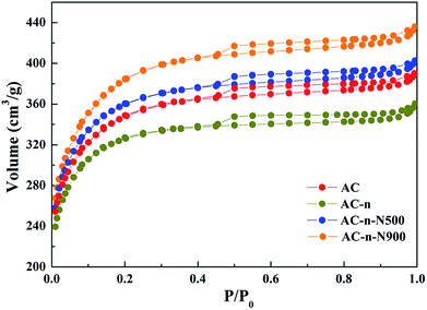
In order to investigate the physical structures of activated carbon, the Brunauer–Emmett–Teller (BET) method was employed to clarify specific textural parameters of the as-prepared materials. In addition, TPD experiments were carried out to characterize the surface chemistry of activated carbon materials.The textural parameters of the three samples were calculated from the nitrogen physisorption experiments and are summarized in Table 1. Results suggested that no significant differences in textural properties exist among the activated carbons that were thermally treated in inert atmosphere and under different temperatures. The specific surface area and pore volume for all the materials increased, which might be caused by the sharp decrease in oxygenated groups.
| Sample | SBET (m2 g−1) | Dpore (nm) | Vpore (cm3 g−1) | VMicrop. (cm3 g−1) | VMecrop. (cm3 g−1) |
|---|---|---|---|---|---|
| AC-n | 1012.82 | 2.20 | 0.5576 | 0.3357 | 0.2219 |
| AC-n-500 | 1126.22 | 2.21 | 0.6225 | 0.3440 | 0.2785 |
| AC-n-900 | 1216.95 | 2.22 | 0.6743 | 0.3146 | 0.3597 |
It has been reported in many studies that thermal treatments for activated carbon under inert atmosphere did not engender drastic changes to its textural properties,21,22 which conforms with the results summarized in Table 1.
| Samples | CO2 (μmol g−1 s−1) | CO (μmol g−1 s−1) | O wt% |
|---|---|---|---|
| AC-n | 301.3 | 593.3 | 1.9 |
| AC-n-N500 | 103.2 | 686.5 | 1.4 |
| AC-n-N900 | 0 | 155.2 | 0.2 |
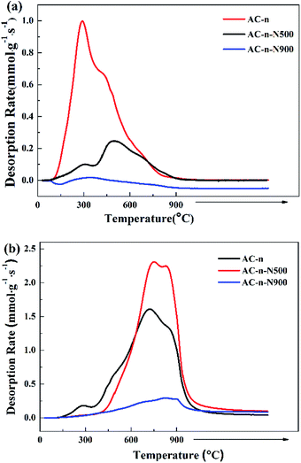
As expected, the data in Fig. 2 and Table 2 show that amount of surface oxygen groups in the AC-n samples decreased upon thermal treatment. However, thermal treatment at different temperatures led to different surface chemistries of the carbon materials. Treatment at 500 °C under nitrogen atmosphere resulted in the decomposition of carboxylic acid groups. Further, almost all of the surface oxygen groups decomposed at 900 °C. The results of the TPD profiles were consistent with those obtained in a previous study.23
In summary, the modified activated carbon differs widely in surface oxygen content and the nature of the surface oxygen groups from the untreated activated carbon. Therefore, when this series of samples were used as supports for SILP materials, the effects of surface oxygen chemistry on IL distribution and the interfacial effect of the SILP materials can be analyzed.
3.2 SILP materials properties
In SILP materials, it is likely that ionic liquids can be distributed on both external and internal surfaces of the supports. Therefore, it is relevant to investigate the effect of surface chemical properties of activated carbon on dispersion behavior of ionic liquid on SILP materials. In the present study, we analyzed the physical properties of SILP materials with different IL loadings, namely, surface area, pore volume, pore diameter distribution, and blocked porosity. Furthermore, we studied the stability of the SILP materials in water using weighing method.| Sample | SBET (m2 g−1) | Dpore (nm) | Vpore (cm3 g−1) | VMicrop. (cm3 g−1) | VMecrop. (cm3 g−1) |
|---|---|---|---|---|---|
| AC-n | 1012.82 | 2.20 | 0.5576 | 0.3357 | 0.2219 |
| AC-n-10% IL | 863.60 | 2.29 | 0.4530 | 0.2184 | 0.2346 |
| AC-n-20% IL | 297.70 | 2.42 | 0.1794 | 0.0260 | 0.1534 |
| AC-n-40% IL | 17.07 | 5.97 | 0.0255 | 0.0017 | 0.0238 |
| AC-n-500 | 1126.22 | 2.21 | 0.6225 | 0.3440 | 0.2785 |
| AC-n-500-10% IL | 975.95 | 2.24 | 0.5184 | 0.2577 | 0.2607 |
| AC-n-500-20% IL | 521.88 | 2.41 | 0.3145 | 0.1015 | 0.2130 |
| AC-n-500-40% IL | 25.32 | 4.88 | 0.0308 | 0.0025 | 0.0283 |
| AC-n-900 | 1216.95 | 2.22 | 0.6743 | 0.3146 | 0.3597 |
| AC-n-900-10% IL | 1094.67 | 2.22 | 0.5697 | 0.2849 | 0.2848 |
| AC-n-900-20% IL | 724.59 | 2.24 | 0.4058 | 0.1351 | 0.2707 |
| AC-n-900-40% IL | 89.77 | 3.18 | 0.0715 | 0.0052 | 0.0663 |
| Sample | 1 | 2 | 3 | 4 |
|---|---|---|---|---|
| Total pore volume (cm3 g−1) | Not accessible pore volume (cm3 g−1) | Loaded IL volume (cm3 g−1) | Blocked porosity (cm3 g−1) | |
| a 1 – Total pore volume, determined by amount adsorbed at P/P0 = 0.99 in N2 adsorption isotherm at −196 °C. 2 – Pore volume not accessible to N2 determined as total pore volume of support AC minus total pore volume of SILP samples. 3 – Amount of IL in SILP samples (loaded IL volume calculated with ρ = 1.08 g cm−3). 4 – Calculated by difference of columns 2 and 3. In parentheses: percentage of support total pore volume marked as XV, that is (blocked porosity (cm3 g−1)/support total pore volume (cm3 g−1)) × 100. | ||||
| AC-n | 0.5576 | — | — | — |
| AC-n-10% IL | 0.4530 | 0.1046 | 0.0926 | 0.0120 (2.15%) |
| AC-n-20% IL | 0.1794 | 0.3782 | 0.1852 | 0.1930 (34.61%) |
| AC-n-40% IL | 0.0255 | 0.5321 | 0.3704 | 0.1617 (29.00%) |
| AC-n-N500 | 0.6225 | — | — | — |
| AC-n-N500-10% IL | 0.5184 | 0.1041 | 0.0926 | 0.0155 (1.85%) |
| AC-n-N500-20% IL | 0.3145 | 0.3080 | 0.1852 | 0.1228 (19.73%) |
| AC-n-N500-40% IL | 0.0308 | 0.5917 | 0.3704 | 0.2213 (35.55%) |
| AC-n-N900 | 0.6743 | — | — | — |
| AC-n-N900-10% IL | 0.5697 | 0.1046 | 0.0926 | 0.0120 (1.78%) |
| AC-n-N900-20% IL | 0.4058 | 0.2655 | 0.1852 | 0.0803 (11.91%) |
| AC-n-N900-40% IL | 0.0715 | 0.5998 | 0.3704 | 0.2294 (34.02%) |
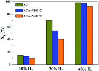
Table 4 shows that the pores of all samples were blocked to a certain extent, which has been previously reported.20 This is because the ionic liquid did not exist as a uniform or consecutive film. For the three samples, with the increase in IL loading, the blocked porosity of AC-n first rose and then dropped, while that of both AC-n-N500 and AC-n-N500 increased monotonically. When IL loading is 10 wt%, the blocked porosity for all samples was relatively low and almost the same as interface interaction between IL and active carbon played a predominant role, leading to well distributed IL on different active carbon materials. However, when IL loading reached 20 wt%, the blocked porosity of the three samples exhibited significant differences. The blocked porosity of AC-n was 34.61%, while that of AC-n-500 was only 11.91%. These results suggested that larger interaction exists between IL and the surface of active carbon calcinated at high temperature, promoting the dispersion of IL over the active carbon and thus decreasing the blocked porosity. Therefore, the variation in blocked porosity is mainly related to the loading amounts of IL and surface chemistry of the supports.
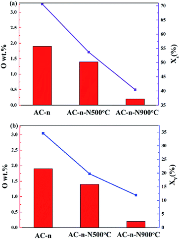
To investigate the influence of the surface chemistry of activated carbon on blocked porosity, the relationship between surface oxygen content of carbon materials and decrease in their pore volume and surface area was obtained. As shown in Fig. 4a and b, the BET surface area and the blocked porosity of pore volume within SILP materials were drastically decreased due to the reduction of surface oxygen content. Hence, we considered that the distribution performance of IL was related to the surface oxygen content of carbon materials.
Fig. 5 shows the colour change of the filtrate in AgNO3 solution with the increase in washing. As the washing cycles increased, the colour of filtrate in AgNO3 solution changed from ivory-white to watery-white, suggesting that less ionic liquid was being washed off. Furthermore, we employed the Mohr method (GB11896-89) to analyze the amount of chloridion in the filtrate. Table 5 showed that concentration of chloridion in the filtrate decreased with the washing cycle. When the washing cycle increased to four times, for these three samples, concentration of chloridion in the filtrate was only 100 ppb. There are two reasons accounting for this finding: the first is that most of the ionic liquid was washed away by the water; the second is that part of the ionic liquid was difficult to wash off because of strong interactions between ionic liquid and active carbon.
| Sample | First wash (CCl−: mol L−1) | Second wash (CCl−: mol L−1) | Third wash (CCl−: mol L−1) | Fourth wash (CCl−: mol L−1) |
|---|---|---|---|---|
| AC-n | 5.19 × 10⁻³ | 6.97 × 10⁻⁴ | 5.81 × 10⁻⁵ | 6.12 × 10⁻⁷ |
| AC-n-N500 | 3.52 × 10⁻³ | 2.10 × 10⁻⁴ | 2.07 × 10⁻⁵ | 6.08 × 10⁻⁷ |
| AC-n-N900 | 2.13 × 10⁻³ | 1.09 × 10⁻⁴ | 2.08 × 10⁻⁵ | 6.01 × 10⁻⁷ |
Table 6 suggests that the ionic liquid loaded on the carbon materials was not washed completely. Furthermore, the residual quantity of the ionic liquid on active carbon varied among different treatment methods.
| Sample | Theoretical value/g | Actual value/g | Actual immobilization/% |
|---|---|---|---|
| AC-n | 5.5 | 5.08 | 1.6 |
| AC-n-500 | 5.5 | 5.12 | 2.4 |
| AC-n-900 | 5.5 | 5.18 | 3.6 |
After four washing cycles, the actual immobilization values of AC-n, AC-n-500 and AC-n-900 with 10 wt% IL loading were 1.6%, 2.4% and 3.6%, respectively. A number of studies have reported that surface polarity of AC supports was enhanced by the increase in surface oxygen content, making them adsorb polar molecules more easily. However, this theory does not explain the results obtained in this experiment as the actual immobilization amount increased with the reduced surface oxygen content of the AC support (Tables 2 and 6).
Therefore, three aspects must be considered to explain these results. (i) The first aspect is the phase state of immobilized ionic liquid. For example, Hu et al.26 proposed that the coexistence of liquid and solid phases for ionic liquid was intuitively observed on the surface of mica using atomic force microscopy (AFM). Also, the drop-on-the-layer phenomenon, proposed by this group, was believed to be a special microscopic property of liquids when contacted with a solid surface. Furthermore, the drop layer had the natural property of the bulk phase. In addition, Hardacre et al.27 proposed multilayer stacking of ILs on the surface of Si (111) wafers using X-ray diffraction. Therefore, in our study, liquid and solid phases of the ionic liquid may coexist on the carbon materials, from which the liquid phase is easily leached, but the solid phase is hardly leached. (ii) The H atom in the C2 position of imidazolium cation of the ionic liquid possesses high acidity to easily form CH–π hydrogen bond with free π-electrons. For example, Sheng Su et al.28 proposed a strong interaction between IL and CNT from thermogravimetric characterization and further verified the formation of CH–π hydrogen bond29–31 between IL and CNT using X-ray diffraction and FTIR spectra. The properties of hydrogen bonds have been studied by a number of researchers.32–34 In nanoscience, the π–H hydrogen bonds are currently characterized by their weak interaction strength, where the contribution of dispersion energy dominates upon the formation and stabilization of the analysed system.35 (iii) Carbon materials having C![[double bond, length as m-dash]](https://www.rsc.org/images/entities/char_e001.gif) C bonds, particularly oxygen-free carbon materials can release some amount of free π-electrons.36–38
C bonds, particularly oxygen-free carbon materials can release some amount of free π-electrons.36–38
As shown in Fig. S1,† it reported that the content of C![[double bond, length as m-dash]](https://www.rsc.org/images/entities/char_e001.gif) C bond increased through thermal treatment and hence, C
C bond increased through thermal treatment and hence, C![[double bond, length as m-dash]](https://www.rsc.org/images/entities/char_e001.gif) C bonds can release more free π-electrons.39,40 Therefore, we suggest a reasonable explanation for the immobilization behaviour of ionic liquid. The interaction between IL and the surface of active carbon, viz., the CH–π hydrogen bond, has a crucial effect on the stability of IL supported on carbon materials. As shown in Fig. 6, there are two phases of IL on the activated carbon. One is called the “solid-phase ionic liquid”, where IL is well-distributed on the support through the formation of CH–π hydrogen bonds between IL and the surface of AC. The other phase of ionic liquid, apart from the disordered molecular arrangement on the surface of active carbon, is called the “liquid-phase ionic liquid” and its physicochemical property is similar to that of the ionic liquid in bulk phase, which is easily washed off by water. In this experiment, a large number of oxygen functional groups were introduced by treating the activated carbon with concentrated nitric acid and thus, the density of free π-electrons decreased and consequently, the intensity of CH–π hydrogen bonds between IL and the surface of AC was weakened. As a result, the ionic liquid became unstable and could easily be washed from the support. However, when active carbons were calcined under inert gas, the surface oxygen decomposed and desorbed in the form of carbon monoxide and carbon dioxide, thus increasing the density of free π-electrons. In this case, the interaction intensity between IL and surface of active carbon enhanced and hence, the IL was more difficult to wash off.
C bonds can release more free π-electrons.39,40 Therefore, we suggest a reasonable explanation for the immobilization behaviour of ionic liquid. The interaction between IL and the surface of active carbon, viz., the CH–π hydrogen bond, has a crucial effect on the stability of IL supported on carbon materials. As shown in Fig. 6, there are two phases of IL on the activated carbon. One is called the “solid-phase ionic liquid”, where IL is well-distributed on the support through the formation of CH–π hydrogen bonds between IL and the surface of AC. The other phase of ionic liquid, apart from the disordered molecular arrangement on the surface of active carbon, is called the “liquid-phase ionic liquid” and its physicochemical property is similar to that of the ionic liquid in bulk phase, which is easily washed off by water. In this experiment, a large number of oxygen functional groups were introduced by treating the activated carbon with concentrated nitric acid and thus, the density of free π-electrons decreased and consequently, the intensity of CH–π hydrogen bonds between IL and the surface of AC was weakened. As a result, the ionic liquid became unstable and could easily be washed from the support. However, when active carbons were calcined under inert gas, the surface oxygen decomposed and desorbed in the form of carbon monoxide and carbon dioxide, thus increasing the density of free π-electrons. In this case, the interaction intensity between IL and surface of active carbon enhanced and hence, the IL was more difficult to wash off.
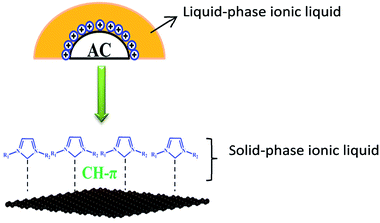 | ||
| Fig. 6 Schematic of interaction between ionic liquid and carbon surface (orange: liquid-phase ionic liquid; blue: solid-phase ionic liquid). | ||
Moreover, the disparity of IL supported on activated carbon depended on the density of the surface free π-electrons due to the formation of CH–π bonds between the surface of AC and IL. The blocked porosity could not be easily formed because of the surface chemical effects with low IL loading. Comparing the data for the three SILP samples with 20 wt% IL loading, we found that supporting IL on AC-n resulted in the highest blocked porosity because of the lower density of free π-electrons on the support, causing disorder of IL at the interface. On the contrary, the distribution of IL was more ordered on the supports with high temperature treatment for the formation of CH–π bonds between the surface of AC and IL.
4 Conclusion
The distribution behavior of ionic liquid supported on porous carbon materials was investigated using a series of carbon supports with a variety of textural, chemical and morphological properties. We found that the blocked porosity of the ionic liquid on SILP materials was not only related to the amount of ionic liquid, but also to the surface oxygen content. The blocked porosity decreased for carbon materials with low surface oxygen content. Furthermore, the stability of the supported IL was tested in water until the IL was not leached. We discovered that the supported IL was not easily washed from the activated carbon with low concentration of surface oxygen groups because the oxygen-free supports have a high density of free π-electrons and the H atom on the C2 position of the acidic cation in the IL structure forms a CH–π bond with the surface π-electrons on carbon materials. In addition, we proposed that the distribution of ionic liquid supported on thermally treated activated carbon could be enhanced by increasing the density of surface free π-electrons of carbon materials. While investigating IL loading, the supported IL led to some blocked porosity for three different carbons. However, the distribution of IL on the surface of activated carbon supports with high temperature treatment is much more ordered than that on the merely oxidized activated carbon support. These results showed that the formation of CH–π hydrogen bonds between the ionic liquids with imidazole ring and carbon materials with high free π-electrons can enhance the dispersion of ionic liquid on the surface of the support.Conflicts of interest
There are no conflicts to declare.Acknowledgements
Financial support by the National Natural Science Foundation of China (NSFC; Grant 21606199, 21476207) is gratefully acknowledged.Notes and references
- K. R. Seddon, J. Chem. Technol. Biotechnol., 1997, 68, 351–356 CrossRef.
- P. Wasserscheid and W. Keim, Angew. Chem., Int. Ed., 2000, 39, 3772–3789 CrossRef PubMed.
- E. D. Bates, R. D. Mayton, I. Ntai and J. H. Davis, J. Am. Chem. Soc., 2002, 124, 926–927 CrossRef PubMed.
- M. E. Bluhm, M. G. Bradley, R. Butterick, U. Kusari and L. G. Sneddon, J. Am. Chem. Soc., 2006, 128, 7748–7749 CrossRef PubMed.
- G. B. Damas, A. B. A. Dias and L. T. Costa, J. Phys. Chem. B, 2014, 118, 9046–9064 CrossRef PubMed.
- K. B. Sezginel, S. Keskin and A. Uzun, Langmuir, 2016, 32, 1139–1147 CrossRef PubMed.
- Y. F. Chen, Y. Y. Zhang, S. J. Yuan, X. Y. Ji, C. Liu, Z. H. Yang and X. H. Lu, J. Chem. Eng. Data, 2016, 61, 3428–3437 CrossRef.
- Q. H. Zhang, S. G. Zhang and Y. Q. Deng, Green Chem., 2011, 13, 2619–2637 RSC.
- F. Jutz, J. M. Andanson and A. Baiker, Chem. Rev., 2011, 111, 322–353 CrossRef PubMed.
- P. Zhang, T. B. Wu and B. X. Han, Adv. Mater., 2014, 26, 6810–6827 CrossRef PubMed.
- E. S. Farrell and G. E. Pacey, Anal. Chem., 2000, 72, 1819–1822 CrossRef PubMed.
- X. Q. Sun, H. M. Luo and S. Dai, Chem. Rev., 2012, 112, 2100–2128 CrossRef PubMed.
- E. R. Cooper, C. D. Andrews, P. S. Wheatley, P. B. Webb, P. Wormald and R. E. Morris, Nature, 2004, 430, 1012–1016 CrossRef PubMed.
- B. K. Price, J. L. Hudson and J. M. Tour, J. Am. Chem. Soc., 2005, 127, 14867–14870 CrossRef PubMed.
- Q. H. Zhang and J. M. Shreeve, Chem. Rev., 2014, 114, 10527–10574 CrossRef PubMed.
- J. Y. Wang, H. B. Chu and Y. Li, ACS Nano, 2008, 2, 2540–2546 CrossRef PubMed.
- J. Lemus, J. Palomar, M. A. Gilarranz and J. J. Rodriguez, Adsorption, 2011, 17, 561–571 CrossRef.
- M. Haumann, A. Schönweiz, H. Breitzke, G. Buntkowsky, S. Werner and N. Szesni, Chem. Eng. Technol., 2012, 35, 1421–1426 CrossRef.
- M. T. Heinze, J. C. Zill, J. Matysik, W. D. Einicke, R. Glaser and A. Stark, Phys. Chem. Chem. Phys., 2014, 16, 24359–24372 RSC.
- M. Rufete-Beneite, M. C. Roman-Martinez and A. Linares-Solano, Carbon, 2014, 77, 947–957 CrossRef.
- E. G. Rodrigues, M. F. R. Pereira, X. W. Chen, J. J. Delgado and J. J. M. Orfao, J. Catal., 2011, 281, 119–127 CrossRef.
- J. A. Menendez, J. Phillips, B. Xia and L. R. Radovic, Langmuir, 1996, 12, 4404–4410 CrossRef.
- J. H. Xu, J. Zhao, J. T. Xu, T. T. Zhang, X. N. Li, X. X. Di, J. Ni, J. G. Wang and J. Cen, Ind. Eng. Chem. Res., 2014, 53, 14272–14281 CrossRef.
- J. G. Huddleston, A. E. Visser, W. M. Reichert, H. D. Willauer, G. A. Broker and R. D. Rogers, Green Chem., 2001, 3, 156–164 RSC.
- Z. J. Chen, Z. P. Li, X. Y. Ma, P. F. Long, Y. Zhou, L. Xu and S. G. Zhang, Green Chem., 2017, 19, 1303–1307 RSC.
- Y. Liu, Y. Zhang, G. Wu and J. Hu, J. Am. Chem. Soc., 2006, 128, 7456–7457 CrossRef PubMed.
- J. C. Adrian, H. Christopher and D. H. John, Mol. Phys., 2001, 99, 795–800 CrossRef.
- Y. X. Ding and D. S. Su, ChemSuschem, 2014, 7, 1542–1546 CrossRef PubMed.
- S. J. Grabowski, Chem. Rev., 2011, 111, 2597–2625 CrossRef PubMed.
- D. A. Rodham, S. Suzuki, R. D. Suenram, F. J. Lovas, S. Dasgupta, W. A. Goddard and G. A. Blake, Nature, 1993, 362, 735–737 CrossRef.
- S. Tsuzuki, K. Honda, T. Uchimaru, M. Mikami and K. Tanabe, J. Am. Chem. Soc., 2000, 122, 11450–11458 CrossRef.
- P. Tarakeshwar, H. S. Choi and K. S. Kim, J. Am. Chem. Soc., 2001, 123, 3323–3331 CrossRef PubMed.
- S. Vaupel, B. Brutschy, P. Tarakeshwar and K. S. Kim, J. Am. Chem. Soc., 2006, 128, 5416–5426 CrossRef PubMed.
- D. Kim, P. Tarakeshwar and K. S. Kim, J. Phys. Chem. A, 2004, 108, 1250–1258 CrossRef.
- E. C. Lee, D. Kim, P. Jurečka, P. Tarakeshwar, P. Hobza and K. S. Kim, J. Phys. Chem. A, 2007, 111, 3446–3457 CrossRef PubMed.
- D. Sebastián, Carbon, 2010, 48, 4421–4431 CrossRef.
- Z. Hashisho, M. J. Rood, S. Barot and J. Bernhard, Carbon, 2009, 47, 1814–1823 CrossRef.
- Z. Tabti and R. Ruiz-Rosas, ACS Appl. Mater. Interfaces, 2014, 6, 11682–11691 CrossRef PubMed.
- M. Baranac-Stojanović, A. Koch and E. Kleinpeter, Chemistry, 2012, 18, 370 CrossRef PubMed.
- S. Sarkar, S. Niyogi and E. Bekyarova, Chem. Sci., 2011, 2, 1326–1333 RSC.
Footnote |
| † Electronic supplementary information (ESI) available. See DOI: 10.1039/c8ra03033b |
| This journal is © The Royal Society of Chemistry 2018 |

