 Open Access Article
Preparation of Co–N carbon nanosheet oxygen electrode catalyst by controlled crystallization of cobalt salt precursors for all-solid-state Al–air battery†
Jianhua Shen a,
Lu Menga,
Yanyan Liua,
Cheng Chen
 b,
Yihua Zhu
 *a and
Chunzhong Li
 *a
*a
aKey Laboratory for Ultrafine Materials of Ministry of Education, School of Materials Science and Engineering, East China University of Science and Technology, Shanghai 200237, P. R. China. E-mail: yhzhu@ecust.edu.cn; czli@ecust.edu.cn; Tel: +86 021 64252022 Tel: +86 021 6425094
bSchool of Environmental and Materials Engineering, College of Engineering, Shanghai Polytechnic University, Shanghai 201209, China
First published on 18th June 2018
Abstract
Production of bifunctional catalysts for catalyzing both the oxygen reduction reaction (ORR) and oxygen evolution reaction (OER) is highly advisable but challenging with respect to the applications of these catalysts in renewable energy conversion and storage technologies. Herein, we prepared highly reactive and stable cobalt-embedded nitrogen-rich carbon nanosheets (Co–N/CNs). Based on density functional theory (DFT) calculations and experiments, the as-prepared Co–N/CNs showed outstanding catalytic activities toward both OER and ORR. The optimized Co–N/CNs-800 catalyst revealed outstanding bifunctional catalytic activities for both ORR and OER with high catalytic efficiency and long-term durability, which were even comparable with those of the state-of-the-art Pt/C and RuO2 catalysts. Furthermore, we observed that different cobalt salt precursors affected the size of Co nanoparticles, and both ORR and OER catalytic activities displayed completely consistent variations (sulfate < acetate < chloride < nitrate). An all-solid-state Al–air battery device comprising this hybrid catalyst showed superior performance when compared with the device containing the Pt/C catalyst.
1. Introduction
The continuous depletion of traditional fossil fuels and the associated environmental pollution have increased the demand for clean and sustainable energy sources such as rechargeable metal–air batteries, fuel cells and water-splitting devices.1–3 These new energy conversion and storage technologies, which are driven by the oxygen reduction reaction (ORR) and oxygen evolution reaction (OER) as the crucial electrode processes, have been universally studied and developed because of their high energy densities.4 Currently, platinum-group-based catalysts are considered to be the best electrocatalysts for ORR or OER, but they are expensive and scarce largely due to their limited large-scale applications.5 In addition, it is difficult for the same catalyst to synchronously accelerate ORR/OER activities, which is highly desirable yet a great challenge.6,7In the past decades, some alternative materials have been developed, and they exhibit bifunctional catalytic activities toward both OER and ORR.5–8 For example, carbon nanomaterials (especially N-doped carbons with a break of electroneutrality and charge of local change density) have demonstrated promising OER and ORR activities and stabilities due to their low cost, adjustable surface chemistry and high electrical conductivity.9 Moreover, recent evidence indicates that the ORR active sites are carbon atoms next to pyridinic nitrogen with Lewis basicity in the N-doped nanocarbons.10 However, the density of N-doped carbons is limited by the preparation method such as annealing of carbon nanomaterials in NH3 atmosphere and direct pyrolysis of N-containing hydrocarbons or macromolecules.9 In particular, it is difficult to determine the suitable heat treatment temperature. Without optimization, unduly low or extremely high temperatures lead to low electronic conductivity or considerable loss of active N species, respectively.11 Hence, a substantial increase in the effective active sites in N-doped nanocarbons remains challenging.
In this regard, recent studies have shown that Co-doping with transition metals and N carbons (M–N/C) could further enhance the bifunctional electrocatalytic activity through the introduction of more active additives and their synergistic effects;12 among these catalysts, Co–N/C nanocomposites have been extensively studied as promising ORR catalysts owing to strong interactions between Co-embedded and N-doped species in the carbon frameworks.8,13 Zou et al. reported cobalt-embedded nitrogen-rich CNTs via thermal treatment of Co2+-functionalized graphitic carbon nitride (Co2+-g-C3N4) at 700 °C in an N2 atmosphere.14 Due to the catalytic effect of cobalt ions, CNT-based materials are used to catalyse electrochemical reaction automatically. Through comparison with studies by Xie et al., the surface cobalt atoms in two-dimensional nanosheets exhibited higher intrinsic activities and stabilities than bulk materials.15 However, many problems still exist in the preparation and design of 2D nanomaterials with controlled mesopores and compositions.
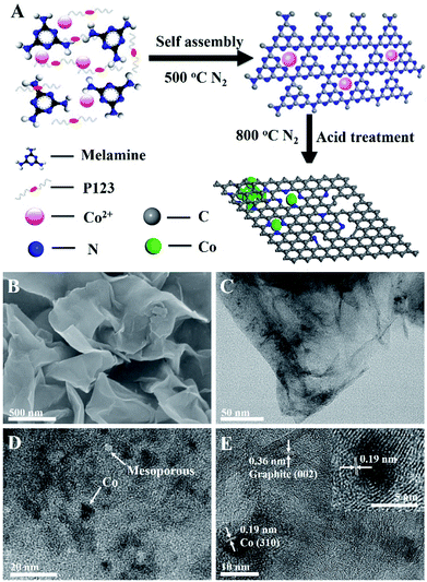
Herein, we demonstrate an efficient method, wherein Co-embedded N-rich carbon nanosheets (Co–N/CNs) (Fig. 1A) can be developed as highly active bifunctional electrocatalysts for OER and ORR under alkaline conditions. The synergistic effect between Co and N-doping leads to improved electrocatalytic performance, and the oxygen electrode activity parameter ΔE (the criteria for judging the overall catalytic activity of bifunctional electrocatalysts) value for the well-designed catalyst is 0.84 V, which exceeds those of Pt/C and RuO2 catalysts as well as those of most non-precious metal catalysts reported in previous literature studies. Density functional theory (DFT) was applied to study the effects of Co- and N-doping in carbon nanosheets, and the activation energy of ORR decreased significantly on the surface of multi-doped carbon nanosheets, accounting for the enhanced catalytic performance. Interestingly, an all-solid-state Al–air battery was constructed using Co–N/CN electrodes, and it showed good electrochemical performance and high stability, which was superior to that of Pt/C catalyst.
2. Experimental section
Material synthesis
In the typical procedure, melamine (0.75 g), Co(NO3)2·6H2O (0.121 g), PEO-PPO-PEO (P123, 0.5 g) and ultrapure water (15 mL) were stirred for about 2 h at room temperature. Then, the solution was dried at 80 °C to remove water. The dried precursor was placed in a crucible and heated to 500 °C to form Co2+-functionalized carbon nitride; subsequently, the mixture was heated to an appointed temperature (700, 800 and 900 °C) at the rate of 3 °C min−1 for 2 h in an N2 atmosphere. Unstable and inactive species were removed from the heat-treated samples via pre-leaching in 0.5 M H2SO4 at 80 °C for 24 h. The products are referred to as Co–N/CNs-X with X being the annealing temperature.Fabrication of all-solid-state Al–air battery
A home-made Al–air battery device was employed for battery performance and stability measurements. Alkaline polymer electrolyte films were prepared by the solution casting method. PVA (2.0 g) was dissolved in 20 mL water and stirred for one day. KOH (6.74 g) was dissolved in 20 mL water and stirred until it was completely dissolved. The two solutions were mixed together and stirred again for 25 h. The mixed solutions were poured into Petri dishes and left to dry slowly at 25 °C to form films. These films of about 3 mm thickness were placed in a dry environment with relative humidity of ∼24% for three months. A porous air cathode was prepared by casting a cathodic paste onto a Ni foam. A mixture composed of conductive material (70 mg of activated carbon and 10 mg of ether black) and catalyst (20 mg) was milled together with 8 mg PVDF as the polymer binder. The solid blend was dispersed in NMP to form a viscous paste. PVDF could tightly bind electrode composites to the Ni foam at room temperature. The Ni foam was used as both mechanical support and current collector, and it was stuffed with the cathodic paste. A smooth surface was obtained by the cold press process to sufficiently contact with the gel electrolyte film. Micropores were formed due to the evaporation of the NMP solvent, through which air could penetrate into the porous cathode. A polished Al plate was used as the anode. As a reference material, 20 wt% Pt/C catalyst was prepared using the same procedure.3. Results and discussion
Co–N/CNs were prepared by novel self-assembly and two-step thermal treatment, as shown schematically in Fig. 1A. During the synthesis process, the precursor was self-assembled and further heated at 500 °C in N2 atmosphere to polymerize and form Co2+-functionalized carbon nitride nanosheets, which was similar to the procedure given in the literature.14 Furthermore, the prepared Co–N/CN catalysts were carbonized at high temperature, which reduced Co2+ to Co nanoparticles, thus forming carbon nanosheets. Finally, the resulting materials underwent acid treatment with 0.5 M H2SO4 for 12 h to remove any accessible Co species present. In addition, the effects of different carbonization temperatures (700, 800 and 900 °C) and different Co2+ salt precursors were investigated.In Fig. 1B, the scanning electron microscopy (SEM) image displays typical graphene-like sheet morphology in which no clear nanoparticles can be seen, due to the negligible size of cobalt nanoparticles (Co NPs). Transmission electron microscopy (TEM) images exhibit that the formed Co NPs are uniformly loaded on thin carbon sheets (Fig. 1C and D). The size distribution histogram demonstrates that these Co NPs have an average size of 5.6 nm with narrow distribution. After acid treatment and removal of Co NPs, we can observe the corresponding mesopores (Fig. S1†). Fig. 1E demonstrates the well-defined crystalline lattice spacings of 0.19 and 0.36 nm, which match well with the (310) planes of the Co phase and (002) planes of the graphite phase, respectively. Notably, the Co NPs are surrounded by a few graphitic carbon layers despite acid washing, implying good electrochemical activity and stability for catalytic reactions. The presence of metallic Co and crystalline carbon in Co–N/CNs is affirmed by powder X-ray diffraction (XRD), as shown in Fig. S2.† X-Ray Photoelectron Spectroscopy (XPS) and Thermogravimetric Analysis (TGA) (Fig. S3 and S4†) reveal that the Co/C atomic ratio and wt% of Co in Co–N/CNs-800 are 2![[thin space (1/6-em)]](https://www.rsc.org/images/entities/char_2009.gif) :
:![[thin space (1/6-em)]](https://www.rsc.org/images/entities/char_2009.gif) 100 and 8.84%, respectively.
100 and 8.84%, respectively.
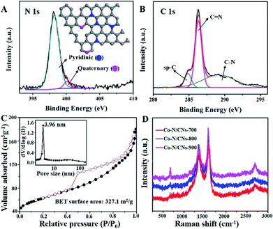
The N 1s XPS spectrum of Co–N/CNs-800 (Fig. 2A) further displays the presence of two types of N species, which can be ascribed to pyridinic (Np) and quaternary (Nq) N atoms. Further quantitative analysis of the XPS result shows that the atomic ratios of N/C [or (Np + Nq)/C], Np/C and Nq/C in Co–N/CNs-800 are 10.3![[thin space (1/6-em)]](https://www.rsc.org/images/entities/char_2009.gif) :
:![[thin space (1/6-em)]](https://www.rsc.org/images/entities/char_2009.gif) 100, 9.3
100, 9.3![[thin space (1/6-em)]](https://www.rsc.org/images/entities/char_2009.gif) :
:![[thin space (1/6-em)]](https://www.rsc.org/images/entities/char_2009.gif) 100, and 1
100, and 1![[thin space (1/6-em)]](https://www.rsc.org/images/entities/char_2009.gif) :
:![[thin space (1/6-em)]](https://www.rsc.org/images/entities/char_2009.gif) 100, respectively. Notably, Np and Nq have been considered as electrochemically active sites in previous studies. The high-resolution spectrum of C 1s (Fig. 2B) can be deconvoluted to several single peaks corresponding to sp-C, C
100, respectively. Notably, Np and Nq have been considered as electrochemically active sites in previous studies. The high-resolution spectrum of C 1s (Fig. 2B) can be deconvoluted to several single peaks corresponding to sp-C, C![[double bond, length as m-dash]](https://www.rsc.org/images/entities/char_e001.gif) N, C–O, C
N, C–O, C![[double bond, length as m-dash]](https://www.rsc.org/images/entities/char_e001.gif) O and C–N, confirming the existence of heteroatoms in hybrids.16 The Co 2p3/2 and 2p1/2 high-resolution spectra correspond to Co(0) and Co–Nx peaks (Fig. S5†).17 Moreover, the Co high-resolution spectra display no peaks consistent with the Coδ (δ > 2) species, which further indicates that Co NPs encapsulated in carbon layers are not sensitive to an aerobic atmosphere to be oxidized.
O and C–N, confirming the existence of heteroatoms in hybrids.16 The Co 2p3/2 and 2p1/2 high-resolution spectra correspond to Co(0) and Co–Nx peaks (Fig. S5†).17 Moreover, the Co high-resolution spectra display no peaks consistent with the Coδ (δ > 2) species, which further indicates that Co NPs encapsulated in carbon layers are not sensitive to an aerobic atmosphere to be oxidized.
The N2 adsorption/desorption isotherm of Co–N/CNs-800 (Fig. 2C) demonstrates type-IV isotherm with a surface area of 327.1 m2 g−1. The mesoporous structure is observed at 4 nm, which is demonstrated by the pore size distributions (the inset of Fig. 2C), and this result is shown in the TEM image in Fig. 1D. Raman measurements are conducted to demonstrate structural defects. In Fig. 2D, the D- and G-bands at approximately 1357 and 1577 cm−1, respectively, clearly demonstrate the existence of disordered and graphitic carbon.18 Furthermore, the intensity ratio of D- and G-bands (ID/IG) slightly decreases with an increase in the annealing temperature, and the values are 0.85 for Co–N/CNs-700, 0.80 for Co–N/CNs-800, and 0.65 for Co–N/CNs-900, indicating that graphitization can be enhanced at higher temperatures.
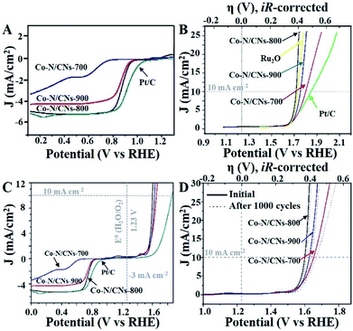
The annealing temperature highly influences the electrocatalytic activities of these M–N/C catalysts, which has been demonstrated previously.19 Therefore, both ORR and OER activities of Co–N/CN catalysts prepared at different temperatures are studied in O2-saturated 0.1 M KOH solutions. Linear sweep voltammetry (LSV) curves indicate that the Co–N/CNs-800 catalyst has positive onset potential (0.98 V) and the highest diffusion-limited current density among the three Co–N/CNs catalysts (Fig. 3A); these values are fractionally lower than those of commercial Pt/C catalyst (1.06 V). The half-wave potential of Co–N/CNs-800 (0.890 V) is more positive than that of the Pt/C catalyst (0.877 V). With respect to ORR activities, the prepared Fe–N/CN catalyst displays lower activity in terms of the onset potential (0.987 V) and half-wave potential (0.845 V) when compared with the synthesized catalysts (Fig. S6†). To further examine the ORR catalytic activities of Co–N/CNs-800 catalysts, LSVs using a rotating disk electrode (RDE) in O2-saturated 0.1 M KOH at various rotating speeds are revealed in Fig. S7.† The voltammetric profiles of Co–N/CNs-800 manifest a typical increase in current density with higher rotation rates (from 400 to 1600 rpm), and the average electron transfer number (n) is 3.98 in the K–L plots (Fig. S8†). High and steady electron transfer number values exhibit that these catalysts favour a four-electron reduction process.20
In addition, the Co–N/CNs-800 catalyst also displayed the best OER activity in terms of overpotential (η) at a current density of 10 mA cm−2, as shown in Fig. 3B. These results could be due to a balance of porosity, electrical conductivity, and type and density of active sites at the optimized temperature (800 °C).21 Co–N/CNs-700 prepared at low temperature exhibited low electrical conductivity, which blocked the charge transfer. Co–N/CNs-900 prepared at high temperature showed lack of catalytically active sites. In our case, Co–N/CNs-800 could obtain significant current density at a small η of ∼0.39 V, approaching the η requirement for commercial RuO2 catalyst. The OER kinetics of the prepared catalysts were further probed through the Tafel slope. The resultant Tafel slopes were approximately 64.4, 67.0, and 168.9 mV dec−1 for Co–N/CNs-800, commercial RuO2, and Pt/C, respectively (Fig. S9†). Notably, Co–N/CNs-800 exhibited the smallest Tafel slope and was therefore the most efficient OER catalyst among the studied catalysts, confirming superior intrinsic OER kinetics of this kind of Co-based material compared with that of the commercial RuO2 catalyst.
To better compare the bifunctional catalytic activities, it is a common method to calculate the oxygen electrode activity parameter ΔE (ΔE = EJ10,OER − EJ-3,ORR). As shown in Fig. 3C, Co–N/CNs-800 exhibited the smallest ΔE (0.84 V), implying the best bifunctional catalytic activity and the highest potential for actual applications. In addition, compared to some reported bifunctional electrocatalysts (Table S1†), Co–N/CNs-800 exhibited high performance, showing great promise for use in rechargeable metal–air batteries. The stabilities of Co–N/CN catalysts were also studied by OER LSV measurements in O2-saturated 0.10 M KOH before and after 1000 cycles. The OER polarization curve of Co–N/CNs-800 displayed almost no change after 1000 cycles (Fig. 3D). On the contrary, no clear change was observed in the ORR current at Co–N/CNs-800. This indicated that the Co–N/CNs-800 electrode possessed higher ORR selectivity and greater tolerance to methanol crossover than the Pt/C catalyst. Additionally, chronoamperometric durability tests for ORR are also shown in Fig. S10.† The Pt/C catalyst displayed 13.2% decrease in activity after 10![[thin space (1/6-em)]](https://www.rsc.org/images/entities/char_2009.gif) 000 s at −0.4 V. In comparison, Co–N/CNs-800 retained a high relative current of 95.8% after 10
000 s at −0.4 V. In comparison, Co–N/CNs-800 retained a high relative current of 95.8% after 10![[thin space (1/6-em)]](https://www.rsc.org/images/entities/char_2009.gif) 000 s, suggesting the increasing stability of active reaction sites on Co–N/CNs-800 than on Pt/C in alkaline solution.
000 s, suggesting the increasing stability of active reaction sites on Co–N/CNs-800 than on Pt/C in alkaline solution.
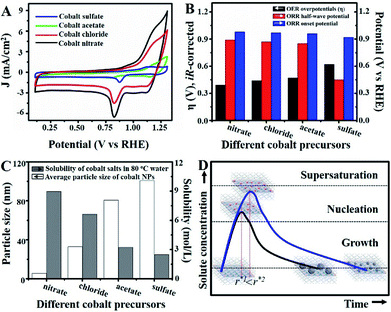
Unlike previous discussions, additional studies were actualized to gain insights into the origin of the superior catalytic activity of Co–N/CNs-800 as well as their structure–catalytic activity relationships. This primarily included the synthesis of materials by self-assembly and pyrolysis of Co–N/CNs with different cobalt precursors (sulfate, acetate, chloride and nitrate), followed by investigation of their electrocatalytic performances. Fig. 4A shows the cyclic voltammograms (CV) of Co–N/CNs prepared using different cobalt precursors, and it displays a substantial reduction process. Apparently, Co–N/CNs (nitrate) revealed pronounced electrocatalytic ORR activity associated with a more positive ORR potential peak and higher current density value than the other samples. Additionally, the rotating disk electrode (RDE) LSV curves and polarization curves of Co–N/CNs with different cobalt precursors are also displayed in Fig. S11.† As the results were almost the same in both cases, we inferred that Co–N/CNs (nitrate) exhibited the best electrochemical catalytic performance. The comparison results are discussed in detail below.
As shown in Fig. 4B, both ORR and OER catalytic activities displayed consistent variations (sulfate < acetate < chloride < nitrate). SEM images of different samples are shown in Fig. S12,† and the most important point is that the corresponding particle sizes showed a constant increase with catalytic activity. Transition metal nanoparticles have been investigated for replacing noble metal-based catalysts, the size of which directly affects catalytic activity.22 Sa et al. developed the general “silica-protective-layer-assisted” approach, and it can preferentially generate small nanoparticles with high catalytic activity sites.23 However, in this study, we accidentally discovered the novel result that the size of transition metal nanoparticles can also be controlled by different precursors (Fig. 4C). The simple solubilities of these cobalt salts were inversely related to the nanoparticle size (specific values in Table S2†). In the schematic diagram of Fig. 4D, the model curves of different solubility precursors (1-low and 2-high solubility) and reaction time display the self-assembly processes including solvent evaporation, nucleation and growth. As shown in Fig. 1, the block copolymer P123 and carbon source were self-assembled to lamellar micelle structures, and Co2+ was adsorbed on the surfaces of these sheets. With volatilization of water, cobalt salts underwent nucleation and growth on these sheets. Furthermore, these cobalt salt crystals were reduced and coated with carbon after high-temperature calcination. Thus, the dimensions of these crystals directly affected the size of final Co nanoparticles in carbon nanosheets. As shown in Fig. S13,† r* is the critical nuclei size:24
 | (1) |
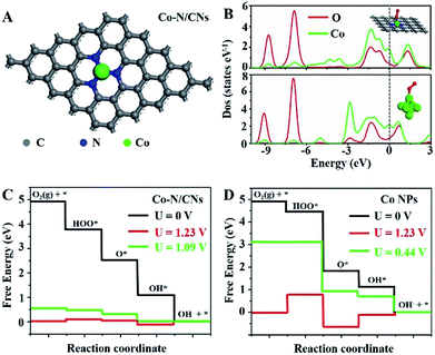
To understand the nature of the high ORR and OER reactivities of Co–N/CNs, density functional theory (DFT) calculations are revealed based on the four-electron pathway mechanism for both ORR and OER in the ESI.† For comparison, both Co–N/CNs and Co nanoparticles were considered, as shown in Fig. 5A and S14.† During the process of ORR, it was very important to understand the adsorption abilities of the surfaces of catalysts. As shown in Fig. 5B, when O2 was adsorbed on CoN3 and Co6 sites, an interaction occurred below −6.5 eV between the O 2s2p-band and Co 3d4s-band near the Fermi level, and the O 2s2p-band was also broadened near the Fermi level. When O2 was adsorbed on the Co6 site, the interaction between the adsorbed O2 and corresponding atoms was weaker than that at the CoN3 site. The free energy diagrams of ORR substeps on active CoN3 sites are presented in Fig. 5C. Desorption of OH− was the last step that became gradient as the potential decreased; this was regarded to be the rate determining step. The rate determining step for the Co6 site was revealed to be the transformation of O2 to OOH* (Fig. 5D). For ORR on CoN3 sites, ORR substeps were all downhill when the electrode potential was 0 V, corresponding to a short circuit condition of fuel cells. As the electrode potential increased to 1.23 V, the reaction steps were all uphill, corresponding to an open circuit condition of fuel cells. Desorption of OH* as OH− became uphill, whereas other subreactions remained downhill at U = 1.09 V; thus, the desorption of OH* as OH− was the rate determining step in ORR.
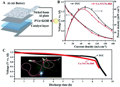
On the basis of the promising electrochemical activity of the as-obtained Co–N/CN catalyst, the Co–N/CNs-800 electrocatalyst was further integrated into an all-solid-state Al–air battery (Fig. 6A). As shown in Fig. 6B, the maximum power density of the Al–air battery using Co–N/CNs-800 catalyst was as high as 41.5 mW cm−2, and it showed similar performance when compared to Pt/C catalyst (43.1 mW cm−2). Moreover, the discharging performances suggested that there was no clear voltage change before the first 8 hours (Fig. 6C), indicating excellent stability of the Co–N/CNs-800 catalyst in Al–air batteries. The inset is an example that demonstrates the potential of our all-solid-state Al–air battery for practical applications. It can be clearly seen that after using three devices connected in series, a white (3.0 V) LED was lit up. These results revealed that the as-obtained Co–N/CNs-800 catalyst has potential in the metal–air battery field.25,26
4. Conclusions
In conclusion, the reaction pathway of ORR/OER has been explored through experimental electrochemical evaluation and theoretical calculations using unique Co NPs in N-doped carbon nanosheets via two-step solid-state thermal reaction approach. The optimized Co–N/CNs-800 catalyst revealed outstanding bifunctional catalytic activities toward both ORR and OER with high catalytic efficiency and long-term durability, which were comparable with those of the state-of-the-art Pt/C and RuO2 catalysts. The results based on the different solubilities of cobalt salt precursors revealed that cobalt nitrate was the best precursor due to the crystal growth law. In addition, the crucial role of atomically dispersed Co was further understood by DFT calculations. The as-prepared Co–N/CNs-800 catalyst also achieved superior performance as an air cathode for an all-solid-state Al–air battery device. This study will pave a new way for designing advanced electrochemical catalysts for new energy conversion systems.Conflicts of interest
There are no conflicts to declare.Acknowledgements
This work was supported by the National Natural Science Foundation of China (21776092, 21471056, 21676093, 91534202), the Basic Research Program of Shanghai (15JC1401300, 17JC1402300), the Shanghai Rising-Star Program (18QA1401500), the Social Development Program of Shanghai (17DZ1200900), Innovation Program of Shanghai Municipal Education Commission, and the Fundamental Research Funds for the Central Universities (222201718002).Notes and references
- J. Shen, Y. Zhu, H. Jiang and C. Li, Nano Today, 2016, 11, 483–520 CrossRef.
- S. Chu and A. Majumdar, Nature, 2012, 488, 294–303 CrossRef PubMed.
- L. Han, S. Dong and E. Wang, Adv. Mater., 2016, 28, 9266–9291 CrossRef PubMed.
- M. K. Debe, Nature, 2012, 486, 43–51 CrossRef PubMed.
- P. Chen, T. Zhou, L. Xing, K. Xu, Y. Tong, H. Xie, L. Zhang, W. Yan, W. Chu, C. Wu and Y. Xie, Angew. Chem., Int. Ed., 2017, 56, 610–614 CrossRef PubMed.
- Z. Li, M. Shao, Q. Yang, Y. Tang, M. Wei, D. G. Evans and X. Duan, Nano Energy, 2017, 37, 98–107 CrossRef.
- I. Yamada, H. Fujii, A. Takamatsu, H. Ikeno, K. Wada, H. Tsukasaki, S. Kawaguchi, S. Mori and S. Yagi, Adv. Mater., 2017, 29, 1603004 CrossRef PubMed.
- B. Y. Xia, Y. Yan, N. Li, H. B. Wu, X. W. Lou and X. Wang, Nat. Energy, 2016, 1, 15006 CrossRef.
- J. Masa, W. Xia, M. Muhler and W. Schuhmann, Angew. Chem., Int. Ed., 2015, 54, 10102–10120 CrossRef PubMed.
- D. Guo, R. Shibuya, C. Akiba, S. Saji, T. Kondo and J. Nakamural, Science, 2016, 351, 361–365 CrossRef PubMed.
- W. Ding, Z. Wei, S. Chen, X. Qi, T. Yang, J. Hu, D. Wang, L. J. Wan, S. F. Alvi and L. Li, Angew. Chem., Int. Ed., 2013, 52, 11755–11759 CrossRef PubMed.
- H. Tang, Y. Zeng, D. Liu, D. Qu, J. Luo, K. Binnemans, D. E. De Vos, J. Fransaer, D. Qu and S. G. Sun, Nano Energy, 2016, 26, 131–138 CrossRef.
- J. Wang, W. Cui, Q. Liu, Z. Xing, A. M. Asiri and X. Sun, Adv. Mater., 2016, 28, 215–230 CrossRef PubMed.
- X. Zou, X. Huang, A. Goswami, R. Silva, B. R. Sathe, E. Milmekova and T. Asefa, Angew. Chem., 2014, 126, 4461–4465 CrossRef.
- S. Gao, Y. Lin, X. Jiao, Y. Sun, Q. Luo, W. Zhang, D. Li, J. Yang and Y. Xie, Nature, 2016, 529, 68–71 CrossRef PubMed.
- S. Li, C. Cheng, X. Zhao, J. Schmidt and A. Thomas, Angew. Chem., Int. Ed., 2018, 57, 1856–1862 CrossRef PubMed.
- Z. Wang, S. Xiao, Z. Zhu, X. Long, X. Zheng, X. Lu and S. Yang, ACS Appl. Mater. Interfaces, 2015, 7, 4048–4055 CrossRef PubMed.
- D. S. Geng, Y. Chen, Y. G. Chen, Y. L. Li, R. Y. Li, X. L. Sun, S. Y. Ye and S. Knights, Energy Environ. Sci., 2011, 4, 760–764 RSC.
- G. Wu, K. L. More, C. M. Johnston and P. Zelenay, Science, 2011, 332, 443–447 CrossRef PubMed.
- M. Li, T. Liu, X. Bo, M. Zhou, L. Guo and S. Guo, Nano Energy, 2017, 33, 221–228 CrossRef.
- H. W. Liang, W. Wei, Z. S. Wu, X. Feng and K. Mullen, J. Am. Chem. Soc., 2013, 135, 16002–16005 CrossRef PubMed.
- M. Lefèvre, E. Proietti, F. Jaouen and J. P. Dodelet, Science, 2009, 324, 71–74 CrossRef PubMed.
- Y. J. Sa, D. J. Seo, J. Woo, J. T. Lim, J. Y. Cheon, S. Y. Yang, J. M. Lee, D. Kang, T. J. Shin, H. S. Shin, H. Y. Jeong, C. S. Kim, M. G. Kim, T. Y. Kim and S. H. Joo, J. Am. Chem. Soc., 2016, 138, 15046–15056 CrossRef PubMed.
- C. Burda, X. B. Chen, R. Narayanan and M. A. El-Sayed, Chem. Rev., 2005, 105, 1025–1102 CrossRef PubMed.
- J. Wang, H. Wu, D. Gao, S. Miao, G. Wang and X. Bao, Nano Energy, 2015, 13, 387–396 CrossRef.
- X. Han, X. Wu, C. Zhong, Y. Deng, N. Zhao and W. Hu, Nano Energy, 2017, 31, 541–550 CrossRef.
Footnote |
| † Electronic supplementary information (ESI) available. See DOI: 10.1039/c8ra03245a |
| This journal is © The Royal Society of Chemistry 2018 |

