 Open Access Article
Impact of bulky phenylalkyl substituents on the air-stable n-channel transistors of birhodanine analogues†
Kodai Iijimaa,
Yann Le Galb,
Dominique Lorcy b and
Takehiko Mori
 *a
*a
aDepartment of Materials Science and Engineering, Tokyo Institute of Technology, O-okayama 2-12-1, Meguro-ku, 152-8552, Japan. E-mail: mori.t.ae@m.titech.ac.jp
bUniv. Rennes, CNRS, ISCR (Institut des Sciences Chimiques de Rennes) - UMR 6226, F-35000 Rennes, France
First published on 21st May 2018
Abstract
By introducing bulky 2-phenylethyl groups into sulfur-rich electron acceptors, 5,5′-bithiazolidinylidene-2,2′-dione-4,4′-dithione and 5,5′-bithiazolidinylidene-2,4,2′,4′-tetrathione, electron transport with the mobility of 0.27 cm2 V−1 s−1 with ambient and long-term stability is achieved in thin-film transistors. Bulky groups destroy the intermolecular S–S network, but the long-term transistor stability is maintained. Here, benzyl groups realize one-dimensional stacking structures, whereas 2-phenylethyl groups lead to herringbone structures.
Introduction
Recent progress in organic transistors have achieved as high mobility as amorphous silicon and oxide semiconductors in the hole-transporting (p-type) materials.1 Electron transporting (n-type) transistors, however, still have lots of room for improvement, particularly from the viewpoint of ambient stability.2 Such n-type molecules as naphthalene diimides, perylene diimides, quinoidal oligothiophenes, and fluorinated acenes have been investigated, in which diimide compounds are suitable for not only small-molecule semiconductors but also components of polymer units. Diketopyrrolopyrrole, isoindigo, benzothiadiazole, and naphtobisthiadiazole are also useful as acceptor units in polymer n-type semiconductors.Previously, we have reported remarkable transistor characteristics and air stability in n-type organic transistors of sulfur-rich acceptors, 3,3′-dialkyl-5,5′-bithiazolidinylidene-2,2′-dione-4,4′-dithione (OS-R) and 3,3′-dialkyl-5,5′-bithiazolidinylidene-2,4,2′,4′-tetrathiones (SS-R) (R = alkyl in Scheme 1).3,4 SS-R compounds show stronger electron acceptor ability than OS-R stemming from the stability of the thiolate units (S−) because the negative charges are largely located on the inner thiocarbonyl groups. SS-Pr shows the highest mobility of 0.26 cm2 V−1 s−1 among this series of materials, and achieves remarkable long-term stability even in the thin-film transistors. SS-R compounds form stacks with anisotropic two-dimensional carrier pathways. On the other hand, OS-R derivatives, which are easily available in a one-step reaction,5 are organized into herringbone structures. These different molecular packings are attributed to the reduced S–S intermolecular interactions in OS-R. OS-Et thin-film transistors exhibit similar performance to SS-Pr. This is likely to come from the isotropic two-dimensional carrier pathways in the herringbone packing.6 Transistors of SS-R maintain the performance for months, but OS-R transistors show slight degradation in air. Although SS-R is a stronger acceptor than OS-R, the excellent air stability has been ascribed to the extensive intermolecular S–S network in the SS-R compounds.3,4
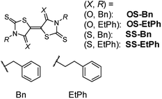 | ||
| Scheme 1 Molecular structures, where R = benzyl (Bn) and 2-phenylethyl (EtPh). Compounds with X = O and S are respectively abbreviated as OS-R and SS-R. | ||
We have reported that performance of transistors based on indigo is remarkably improved by the phenyl substitution.7 Similar enhancement has been achieved thanks to the presence of phenyl rings in thienoisoindigo series.8 In both cases, the improved performance is ascribed to the brickwork structure of the core parts as well as the herringbone arrangement of the phenyl rings. Note also that the presence of bulky substituents is not crippling; in p-type transistors based on TTF derivatives, tert-butyl substitution of hexamethylenetetrathiafulvalene (HMTTF) and dibenzo-TTF (DBTTF), improves the transistor properties due to closely packed organization.9 In the present work, we demonstrate the influence of phenylalkyl substitutions of OS-R and SS-R (Scheme 1). We can expect that such bulky substituents improve the performance and stability of the transistors.
Results and discussion
Synthesis and electronic properties
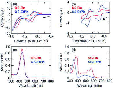
SS-Bn and SS-EtPh were prepared in a similar manner as described in ref. 10. The one-step reaction was used for the synthesis of OS-Bn and OS-EtPh in the presence of triethylamine to complete the reaction.5 We found that the addition of triethylamine was important, otherwise the central double bond remained hydrogenated.The energy levels are estimated using cyclic voltammetry by measuring the redox potentials. In SS-Bn and SS-EtPh, the cyclic voltammograms clearly show two reversible reduction waves, while OS-Bn and OS-EtPh show only a single reversible reduction wave (Fig. 1(a) and (b)). The first half-wave potentials afford the lowest unoccupied molecular orbital (LUMO) levels (ELUMO) as shown in Table 1. The LUMO levels of SS-Bn and SS-EtPh are −4.29 and −4.28 eV, respectively. These values are approximately equal to the previous SS-R,4 indicating that the presence of the N-phenyl alkyl substituents do not significantly modify the electron accepting ability. Therefore, these derivatives are promising candidates to afford air-stable n-type transistor characteristics.12 The LUMO levels of OS-Bn and OS-EtPh are situated above −4.0 eV, as previously observed for other OS-R derivatives.4
| E11/2 (V vs. Fc/Fc+) | E21/2 (V vs. Fc/Fc+) | LUMO (eV) | λedge (nm) | Optical gap (eV) | HOMO (eV) | |
|---|---|---|---|---|---|---|
| a The LUMO levels were estimated by assuming the reference energy level of ferrocene/ferrocenium to be 4.8 eV from the vacuum level.11 The HOMO levels were obtained from the LUMO levels and the optical gaps. | ||||||
| OS-Bn | −0.94 | — | −3.86 | 485 | 2.56 | −6.42 |
| OS-EtPh | −0.99 | — | −3.81 | 483 | 2.57 | −6.38 |
| SS-Bn | −0.51 | −0.94 | −4.29 | 608 | 2.04 | −6.33 |
| SS-EtPh | −0.52 | −0.93 | −4.28 | 607 | 2.04 | −6.32 |
The energy gaps are extracted from the ultraviolet-visible spectra (Fig. 1(c) and (d)). OS-Bn and OS-EtPh show larger gaps (2.6 eV) than those of SS-Bn and SS-EtPh (2.0 eV). The highest occupied molecular orbital (HOMO) levels are estimated by subtracting the optical gaps from the LUMO levels. The HOMO levels are located at approximately the same levels in OS-R and SS-R (Table 1).
Transistor characteristics
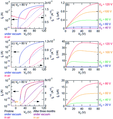
Bottom-gate top-contact thin-film transistors were fabricated by vacuum evaporation of OS-R and SS-R on a SiO2/Si substrate (300 nm SiO2) treated with tetratetracontane (TTC).13 Gold was used as source and drain electrodes. The transistor properties were measured under vacuum and in air (Table 2).| After storage | Measurement | μmax (cm2 V−1 s−1) | μaverage (cm2 V−1 s−1) | Vth (V) | On/off ratio | |
|---|---|---|---|---|---|---|
| OS-Bn | Under vacuum | 7.2 × 10⁻³ | 6.7 × 10⁻³ | 11 | 5 × 10⁵ | |
| In air | 8.1 × 10⁻³ | 6.8 × 10⁻³ | 41 | 4 × 10⁴ | ||
| OS-EtPh | Under vacuum | 2.0 × 10⁻² | 1.5 × 10⁻² | 24 | 8 × 10⁵ | |
| In air | 1.4 × 10⁻² | 1.1 × 10⁻² | 52 | 6 × 10⁵ | ||
| SS-EtPh | Under vacuum | 0.18 | 0.13 | 26 | 1 × 10⁷ | |
| In air | 0.27 | 0.14 | 20 | 9 × 10⁶ | ||
| Three months in air | Under vacuum | 0.19 | 0.17 | 60 | 2 × 10⁷ | |
| In air | 0.20 | 0.17 | 55 | 2 × 10⁷ |
Thin-film transistors of SS-Bn does not work even under vacuum. All the other transistors exhibit n-type transistor characteristics (Table 2). Transfer characteristics of an SS-EtPh thin-film transistor are shown in Fig. 2(e). The measurement in air affords the electron mobility of 0.27 cm2 V−1 s−1. The value is comparable to that of SS-Pr. Since the thin-film transistors of SS-EtPh are stable under ambient conditions, the aging stability is investigated. After stored three months in air, the mobility does not change, though the threshold voltage somewhat increases. In the transistors of SS-Pr, an increase of the off current is observed after the storage. In contrast, the off current of the transistors of SS-EtPh is unchanged. It should be noted that excellent stability is realized even in the thin-film transistors.
OS-Bn shows 10−3 order mobility under vacuum and in the ambient atmosphere. However, the threshold voltage and off current increase in air. OS-EtPh shows an order of magnitude higher mobility than OS-Bn. Only the threshold voltage increases in air. OS-Bn and OS-EtPh show improved stability in comparison with the previously reported OS-R. This may be due to the introduction of the bulky substituents.6
Crystal structures
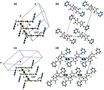
X-ray single crystal structure analyses were carried out for OS-Bn, OS-EtPh, SS-Bn, and SS-EtPh. The crystal data are listed in Table 3. All the molecules are situated on inversion centers. The previous OS-R compounds have herringbone structures,3 but OS-Bn has a stacking structure (Fig. 3). The stacking structure seems to be due to the bulky benzyl groups, where the torsion angle between the core part and the phenyl ring is 105°. The molecules are uniformly stacked along the b axis with the interplanar distance of 3.560 Å. The adjacent columns along the a + c axis are alternately tilted in the opposite directions with respect to the molecular long axes. OS-Bn has the large transfer integral of 75.2 meV along the stacking direction.| OS-Bn | OS-EtPh | SS-Bn | SS-EtPh | |
|---|---|---|---|---|
| a The value in the thin film is in the parentheses. | ||||
| Formula | C20H14N2O2S4 | C22H18N2O2S4 | C20H14N2S6 | C22H18N2S6 |
| Formula weight | 442.58 | 470.64 | 474.70 | 502.76 |
| Crystal system | Monoclinic | Monoclinic | Monoclinic | Orthorhombic |
| Space group | P21/n | P21/c | P21/c | Pccn |
| Shape | Red needle | Orange plate | Dark purple needle | Dark purple plate |
| a (Å) | 18.054(15) | 18.891(7) | 11.9840(3) | 23.6666(4) |
| b (Å) | 4.977(5) | 6.409(3) | 4.79313(10) | 13.6498(2) |
| c (Å) | 11.429(8) | 9.138(4) | 18.2901(4) | 7.17290(10) |
| β (deg.) | 108.13(4) | 93.09(4) | 104.4657(11) | 90 |
| V (Å3) | 976.0(14) | 1104.8(8) | 1017.29(4) | 2317.17(6) |
| Z-value | 2 | 2 | 2 | 4 |
| T (K) | 298 | 298 | 271 | 271 |
| Dcalc (g cm−3) | 1.506 | 1.415 | 1.550 | 1.441 |
| Total reflns. | 3588 | 2475 | 10![[thin space (1/6-em)]](https://www.rsc.org/images/entities/char_2009.gif) 789 789 |
24![[thin space (1/6-em)]](https://www.rsc.org/images/entities/char_2009.gif) 371 371 |
| Unique reflns. (Rint) | 2830 (0.0611) | 1951 (0.1261) | 1860 (0.0495) | 2131 (0.0439) |
| R1 [F2 > 2σ(F2)] | 0.0548 | 0.0660 | 0.0448 | 0.0353 |
| wR2 [all reflns.] | 0.1652 | 0.2475 | 0.1389 | 0.093 |
| GOF | 1.017 | 1.032 | 1.114 | 1.123 |
| XRD d (Å) | 10.8 (001) | 19.0 (∼a) | 15.2 | 18.2 |
| Tilt angle φ (°) | 33 | 24 | 18 | 50 (12)a |
SS-Bn has a stacking structure similar to OS-Bn (Fig. 3), but the adjacent columns are alternately tilted along the c axis because the space group is different from OS-Bn. The interplanar distance of SS-Bn (3.650 Å) is longer than that of OS-Bn, and the intrastack transfer integral (14.0 meV) is much smaller than that of OS-Bn. This is in agreement with the reduced transistor performance.
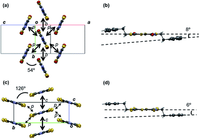
OS-EtPh has a herringbone structure similar to OS-R (Fig. 4). Owing to the ethylene group between the core part and the phenyl ring, the torsion angle is small (8°). The small steric hindrance allows OS-EtPh to form the ordinary herringbone structure similar to OS-R. The dihedral angle is 54°, which is smallest among OS-R. The small dihedral angle leads to a large transfer integral (p) of 22.0 meV.
SS-EtPh has a herringbone structure with a large dihedral angle of 126° (Fig. 4). The structure resembles the θ-phase structure observed in bis(ethylenedithio)tetrathiafulvalene (BEDT-TTF) salts.14 The torsion angle between the core part and the phenyl ring is as small as 6° similarly to OS-EtPh. The previous SS-R compounds have the tilted stacking structure. The large substituent inhibits the intermolecular short S–S contacts (<3.6 Å) to realize a herringbone structure. This is analogous to OS-R, where the weakened intermolecular interactions result in the herringbone structure.3 CH–S interactions exist along the p direction (Fig. S4†), but the transfer integral (p) is very small.
Thin film characterizations
Thin films of the present compounds show sharp X-ray diffraction (XRD) peaks (Fig. 5(a)). The extracted d values are listed in Table 3. A thin film of OS-Bn shows an XRD peak at the d-spacing of 10.8 Å, which corresponds to (001) of the crystal structure. Another peak at the d-spacing of 15.6 Å suggests that the crystal (101) planes are parallel to the substrate, which may correspond to the molecular long axis. Although OS-Bn has two orientations in the thin film, the conducting columns (b) are parallel to the substrate in both orientations. For OS-EtPh, the d-spacing is 19.0 Å, which is almost equal to the crystallographic a axis. For SS-Bn, the d-spacing is 15.2 Å, and the crystal (−102) planes are likely to be parallel to the substrate, which may correspond to the molecular long axis. For SS-EtPh, the d-spacing is 18.2 Å, but this value does not agree with any lattice constants. Since this value is lager than a/2, the molecules in the thin film are less tilted (12°) than those in the crystal (50°). From these results, the tilt angles (φ) of the molecular long axes from the substrate normal are estimated on the basis of φ = cos−1(l/d) (Table 3), where l is the molecular length estimated from the crystal structure. In general, OS-R molecules are more largely tilted (>20°) than SS-R molecules (<20°). The tilt angle of SS-EtPh is particularly small (12°) even compared with the previously investigated SS-R (∼18°). Since small tilt angles are favorable in thin-film transistors,15 this should be related to the improved transistor performance of SS-EtPh.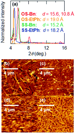 | ||
| Fig. 5 (a) X-ray diffraction patterns of XS-R. Atomic force microscopy (AFM) images of (b) OS-Bn, (c) OS-EtPh, (d) SS-Bn, and (e) SS-EtPh. | ||
Atomic force microscopy (AFM) images of the present compounds show densely packed microcrystals (Fig. 5). In particular, SS-EtPh shows very good crystallinity and smooth packing. This is certainly related to the good transistor performance. SS-Bn shows exceptionally loose packing and poor crystallinity. This should be responsible for the absence of the transistor properties.
Conclusions
We have prepared a new series of electron-transporting organic semiconductors with bulky substituents. Irrespective of the core tetrathione and dithione structures, the benzyl groups realize a stacking structure, whereas the phenylethyl groups lead to herringbone structures. Benzyl groups have a molecular structure with large torsion angles, to construct a one-dimensional staking structure. This is, however, disadvantageous to the transistor properties. SS-Bn dose not show transistor behaviour even under vacuum. This is also due to the poor thin-film morphology and the small transfer integral along the stacking direction, which is five times smaller than OS-Bn. In OS-Bn, the thin-film morphology and the XRD peak indicate high crystallinity, but the transistors show considerably low mobility. This seems to come from the one-dimensional carrier transport.OS-EtPh maintains the usual herringbone structure similar to OS-R. OS-EtPh shows the mobility of the same order of magnitude as the previous OS-R. Phenylalkyl groups have a great influence upon not only the crystal structure but also the stability of the transistor operation. Degradation of the mobility in the ambient conditions, which has been observed in the previous OS-R, is not observed in OS-EtPh. 2-Phenylethyl groups disturb the intermolecular S–S interactions widely observed in SS-R, and SS-EtPh forms a herringbone structure. The thin-film transistors based on SS-EtPh exhibit the highest mobility of 0.27 cm2 V−1 s−1 among the birhodanine derivatives. Although the close intermolecular S–S contacts are largely reduced, this compound exhibits excellent stability of the transistors. The AFM image and the XRD peaks indicate high crystallinity. The d-spacing indicates that the molecules in the thin films are less tilted than the crystals, which is favorable to thin-film transistors.15 This is expected to show the significant improvement of the transistor properties, because the previous SS-R compounds show large tilt angles (∼30°). Accordingly, introduction of bulky substituents is a versatile strategy to improve the stability of the transistor performance.
Conflicts of interest
The authors declare no competing financial interest.Acknowledgements
This work was partly supported by ACT-C Grant Number JPMJCR12ZB from JST, Japan, and by a JPSJ KAKENHI Grant Number 16K13974. We thank the Agence Nationale de la Recherche, France (ANR project No. 12-BS07-0032) for financial support. The authors are grateful to Tokyo Institute of Technology Center for Advanced Materials Analysis for XRD measurement and Prof. Kakimoto for AFM measurements.Notes and references
- (a) Z. Zhang, J.-B. Tan, C.-P. Luo, J.-L. Xie, H.-T. Cai, L.-M. Yang, X.-P. Liu, J.-R. Zhou and C.-L. Ni, Synth. Met., 2014, 195, 147–153 CrossRef; (b) H. Moon, H. Cho, M. Kim, K. Takimiya and S. Yoo, Adv. Mater., 2014, 26, 3105–3110 CrossRef PubMed; (c) Y. Yuan, G. Giri, A. L. Ayzner, A. P. Zoombelt, S. C. B. Mannsfeld, J. Chen, D. Nordlund, M. F. Toney, J. Huang and Z. Bao, Nat. Commun., 2014, 5, 3005 Search PubMed; (d) H. Iino, T. Usui and J.-I. Hanna, Nat. Commun., 2015, 6, 6828 CrossRef PubMed.
- (a) X. Zhan, A. Facchetti, S. Barlow, T. J. Marks, M. A. Ratner, M. R. Wasielewski and S. R. Marder, Adv. Mater., 2011, 23, 268 CrossRef PubMed; (b) Y. Zhao, Y. Guo and Y. Liu, Adv. Mater., 2013, 25, 5372 CrossRef PubMed; (c) C. R. Newman, C. D. Frisbie, D. A. da Silva Filho, J.-L. Brédas, P. C. Ewbank and K. R. Mann, Chem. Mater., 2004, 16, 4436 CrossRef; (d) X. Gao and Y. Hu, J. Mater. Chem. C, 2014, 2, 3099 RSCX. Gao, C. Di, Y. Hu, X. Yang, H. Fan, F. Zhang, Y. Li, H. Li and D. Zhu, J. Am. Chem. Soc., 2010, 132, 3697 CrossRef PubMed; (e) Y. Hu, X. Gao, C. Di, X. Yang, F. Zhang, Y. Liu, H. Li and D. Zhu, Chem. Mater., 2011, 23, 1204 CrossRef; (f) Y. Hu, Z. Wang, X. Zhang, X. Yang, C. Ge, L. Fu and X. Gao, Org. Lett., 2017, 19, 468 CrossRef PubMed; (g) L. Tan, Y. Guo, Y. Yang, G. Zhang, D. Zhang, G. Yu, W. Xu and Y. Liu, Chem. Sci., 2012, 3, 2530 RSC; (h) J. T. E. Quinn, J. Zhu, X. Li, J. Wang and Y. Li, J. Mater. Chem. C, 2017, 5, 8654 RSC; (i) J. Dhar, U. Salzner and S. Patil, J. Mater. Chem. C, 2017, 5, 7404 RSC.
- A. Filatre-Furcate, T. Higashino, D. Lorcy and T. Mori, J. Mater. Chem. C, 2015, 3, 3569 RSC.
- K. Iijima, Y. Le Gal, T. Higashino, D. Lorcy and T. Mori, J. Mater. Chem. C, 2017, 5, 9121 RSC.
- F. Nasiri, A. Zolati and S. Asadbegi, J. Heterocyclic Chem., 2016, 53, 989 CrossRef.
- (a) H. Minemawari, M. Tanaka, S. Tsuzuki, S. Inoue, T. Yamada, R. Kumai, Y. Shimoi and T. Hasegawa, Chem. Mater., 2017, 29, 1245 CrossRef; (b) K. Takimiya, S. Shinamura, I. Osaka and E. Miyazaki, Adv. Mater., 2011, 23, 4347 CrossRef PubMed.
- O. Pitayatanakul, T. Higashino, M. Tanaka, H. Kojima, M. Ashizawa, T. Kawamoto, H. Matsumoto, K. Ishikawa and T. Mori, J. Mater. Chem. C, 2014, 2, 9311 RSC.
- D. Yoo, T. Hasegawa, M. Ashizawa, T. Kawamoto, H. Masunaga, T. Hikima, H. Matsumoto and T. Mori, J. Mater. Chem. C, 2017, 5, 2509 RSC.
- (a) M. Kanno, Y. Bando, T. Shirahata, J. Inoue, H. Wada and T. Mori, J. Mater. Chem., 2009, 19, 6548 RSC; (b) J. Nagakubo, M. Ashizawa, T. Kawamoto, A. Tanioka and T. Mori, Phys. Chem. Chem. Phys., 2011, 13, 14370 RSC.
- (a) C. Roussel, R. Gallo, M. Chanon and J. Metzger, Bull. Soc. Chim. Fr., 1971, 5, 1902 Search PubMed; (b) Y. Le Gal, N. Bellec, F. Barrière, R. Clérac, M. Fourmigué, V. Dorcet, T. Roisnel and D. Lorcy, Dalton Trans., 2013, 42, 16672 RSC; (c) Y. Le Gal, D. Ameline, N. Bellec, A. Vacher, T. Roisnel, V. Dorcet, O. Jeannin and D. Lorcy, Org. Biomol. Chem., 2015, 15, 8479 RSC.
- M. L. Tang, A. D. Reicharrdt, P. Wei and Z. Bao, J. Am. Chem. Soc., 2009, 131, 5264 CrossRef PubMed.
- H. Usta, A. Facchetti and T. J. Marks, Acc. Chem. Res., 2011, 44, 501 CrossRef PubMed.
- (a) M. Kraus, S. Richler, A. Opitz, W. Brütting, S. Haas, T. Hasegawa, A. Hinderhofer and F. Schreiber, J. Appl. Phys., 2010, 107, 094503 CrossRef; (b) M. Kraus, S. Haug, W. Brütting and A. Opitz, Org. Electron., 2011, 12, 731 CrossRef.
- (a) H. Mori, S. Tanaka, T. Mori, A. Kobayashi and H. Kobayashi, Bull. Chem. Soc. Jpn., 1998, 71, 797 CrossRef; (b) H. Mori, S. Tanaka and T. Mori, Phys. Rev. B: Condens. Matter Mater. Phys., 1998, 57, 12023 CrossRef.
- (a) T. Kakinuma, H. Kojima, M. Ashizawa, H. Matsumoto and T. Mori, J. Mater. Chem. C, 2013, 1, 5395 RSC; (b) O. Pitayatanakul, K. Iijima, M. Ashizawa, T. Kawamoto, H. Matsumoto and T. Mori, J. Mater. Chem. C, 2015, 3, 8612 RSC.
Footnote |
| † Electronic supplementary information (ESI) available: Additional information for preparative details, devices fabrication, transistor characteristics, crystal structures. CCDC 1835173–1835176. For ESI and crystallographic data in CIF or other electronic format see DOI: 10.1039/c8ra03362e |
| This journal is © The Royal Society of Chemistry 2018 |

