 Open Access Article
One-pot synthesis of enhanced fluorescent copper nanoclusters encapsulated in metal–organic frameworks†
Bingyan Han,
Xixi Hu,
Mingbo Yu,
Tingting Peng,
Ying Li and
Gaohong He *
*
State Key Laboratory of Fine Chemicals, School of Petroleum and Chemical Engineering, Dalian University of Technology, Panjin, Liaoning 124221, China. E-mail: hgaohong@dlut.edu.cn; Tel: +86427-2631809
First published on 20th June 2018
Abstract
The encapsulation of Cu nanoclusters (Cu NCs) in metal–organic frameworks (MOFs) would improve the properties of Cu NCs. So far, these composites were reported by a two-step synthesis process. In this work, a facile one-pot synthesis of hybridization of glutathione (GSH) protected Cu NCs (Cu NCs@GSH) and MOF-5 (Cu NCs@GSH/MOFs) composites was reported for the first time. The results of UV-vis, TEM, XPS and SEM proved Cu NCs@GSH were distributed homogeneously over the entire MOF structure. The fluorescence intensity of Cu NCs encapsulated in MOF-5 was enhanced about 35-fold owing to the confining scaffold of the MOF and the stability was extended from 3 days to 3 months. Cu NCs@GSH/MOFs composites exhibited strong orange fluorescence and the emissions could change between blue, orange and red as they were partially reversible in different pH environments. This one-pot synthetic strategy could be extended for the encapsulation of fluorescent Ag NCs in MOFs as well. As-prepared Cu NCs@GSH/MOF-5 composites had high stability, and were easily recycled by centrifugation in aqueous solution, therefore, it would be utilized to develop a reusable sensor for detection of metal ions in the future.
Introduction
Metal nanoclusters (NCs) have attracted tremendous attention as the emerging nanomaterials. Composed of several to dozens of metal atoms, their size is less than the Fermi wavelength of an electron.1 Owing to the strong quantum confinement of free electrons in this size regime, they exhibit excellent chemical, physical and optical properties. Photoluminescence (PL) in UV and visible regions is one of the most amazing properties compared to larger metal nanoparticles. Besides noble metal Au and Ag, cheap, non-toxicity and abundant Cu has also been extensively studied.2–4 However, because of susceptibility to oxidation and difficulty in size-control in the process of synthesis, poor stability and low fluorescence quantum yield (QY) are the major challenges of Cu NCs, which have retarded their practical applications and stimulated researchers to develop more simple and effective protocols to prepare Cu NCs. To date, much effort has been devoted to improving these two properties of Cu NCs by optimizing reaction conditions and/or selecting appropriate surface ligands. There have been lots of reports based on this idea involving the optimization of temperature,5 pH values,6 concentration of reactants7,8 and the choice of proper reducing agents. For example, our group just utilized the hydroxylamine hydrochloride as reducing agent instead of hydrazine hydrate to synthesize ultrastable orange-red-emitting Cu NCs for the first time.9 The use of relatively large size capping agents, or special reaction condition, such as microwave assisted,10 or sonochemical synthesis,11 was more conducive to the formation of high-performance Cu NCs. In addition, the strategy of the aggregation-induced emission (AIE),12 and the charge repulsion13 also have been extended to improve the optical properties of Cu NCs.Metal–organic frameworks (MOFs) are a novel class host of highly porous materials constructed from metal ions and organic linkers. Four well-established strategies have been exploited for encapsulating dyes,14,15 polymers,16 biomolecules,17 particularly nanomaterials (NMs) within MOFs according to the order of the growth of the materials: ship-in-bottle strategy (assembly of NCs inside MOFs), bottle-around-ship strategy (assembly of MOFs around NCs), sandwich assembly strategy (embedding NCs between MOFs layers) and in situ encapsulation (simultaneous synthesis of MOFs and NCs).18 The resulting composites enhanced performance characteristics of the guest materials in many fields such as gas storage,19,20 catalysis,21 and sensors.22 Nevertheless, there are only few reports about the encapsulation of fluorescent metal NCs into MOFs to enhance the fluorescence intensity and stability of NCs taking advantages of tunable porosity of MOFs. The combination of Au NCs and zeolitic-imidazolate frameworks-8 (ZIF-8) was applied for the first time in real-time monitoring of drug release.23 The Ag NCs encapsulated in MOFs exhibited enhanced catalytic activity towards the hydrogenation of 4-nitroaniline.24 Wang et al. improved both the stability and the emission intensity of Cu NCs based on their confinement-assisted effect of ZIFs. The emission intensity enhanced 20 times and maintained stable after two weeks compared to several hours.25 However, this method belonged to bottle-around-ship strategy (assembly of ZIFs around NCs) and it involved a two-step synthesis processes: at first Cu NCs cores with uniform sizes, shapes, and structures were prepared, and then ZIFs were assembled on the Cu NCs surfaces. In order to save time and reduce costs, it is even a challenge for the fabrication of Cu NCs/MOFs composites by in situ encapsulation strategy. Because the NCs and MOFs should be formed under the same reaction conditions in this method, synchronous control of the nucleation and growth of these two distinct components was not easy.
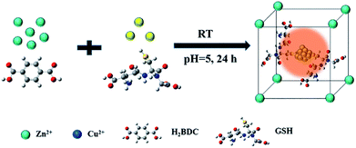
Herein, glutathione (GSH) protected Cu NCs (Cu NCs@GSH) and metal–organic frameworks-5 (MOF-5) were produced simultaneously, and the Cu NCs were encapsulated in MOF-5 shells by a facile one-pot synthesis at room temperature. The fluorescence intensity has been enhanced about 35 folds and the stability prolonged from 3 days to at least 3 months by making use the cavities of the rigid confining scaffold of MOF-5 to stabilize Cu NCs@GSH. Moreover, the Cu NCs@GSH/MOF-5 composites were sensitive to the change of pH and the fluorescence emissions were changed between blue, orange and red reversibly. To the best of our knowledge, it is the first time to obtain hybrid material of Cu NCs@GSH/MOF-5 by one-pot synthesis. Moreover, this idea was also successfully extended to the mode of Ag NCs and MOF-5, where the emission of Ag NCs was improved as well.
Experimental section
Materials
Copper nitrate trihydrate [Cu(NO3)2·3H2O], 1,4-benzenedicarboxylic acid (H2BDC) and GSH were purchased from Sangon Biotechnology Co. Ltd (Shanghai, China). Zinc nitrate hexahydrate [Zn(NO3)2·6H2O] was ordered from STREM CHEMICALS, INC. N,N-dimethylformamide (DMF) was bought from Damao Chemical Reagent Co., Ltd (Tianjin, China). Sodium hydroxide (NaOH) was acquired from Tianli Chemical Reagent Co., Ltd (Tianjin, China).Instrumentation
The UV-visible spectra were recorded using a UV-Vis Cary 60 spectrophotometer at room temperature (Agilent, China). The fluorescence spectra were studied using Hitachi F-7000 fluorescence spectrophotometer (Tokyo, Japan). X-ray photoelectron spectroscopy (XPS) measurements were performed by using a VG Thermo ESCALAB 250 spectrometer. The transmission electron microscope (TEM) images were acquired on a Tecnai G2 F30 S-TWIN. The scanning electron microscope (SEM) was carried out on Nova 450 Nano SEM. X-ray diffraction (XRD) measurements were performed via a Shimadzu 7000S diffract meter using Cu Kα radiation. The zetapotential was performed on Zetasizer Nano-ZEN3700 instrument (Malvern, UK).Synthesis of MOF-5
MOF-5 was synthesized according to the literature with some modifications.25 0.831 g Zn(NO3)2·6H2O and 0.178 g H2BDC were dissolved in 20 mL DMF under stirring until the complete dissolution. Then the mixture was transferred into reaction still for 4 h at 130 °C. White crystals were obtained after cooled to room temperature and filtration. Then the crystals were washed by DMF for several times and dried at 60 °C for 12 h for further use.Synthesis of Cu NCs@GSH
The preparation of Cu NCs@GSH was according to the literature of Luo et al.7 with some modifications. In a typical experiment, 5 mL 50 mg mL−1 GSH solution was added into 5 mL 10 mM Cu(NO3)2 solution under stirring. Then, 2 M NaOH solution was used to adjust the pH value to 5. The mixture turned to be pale yellow transparent solution. After vigorously stirring for 4 h at 37 °C, as-prepared Cu NCs@GSH showed weak orange fluorescence when excited at 380 nm.Synthesis of Cu NCs@GSH/MOF-5 composites
The Cu NCs@GSH/MOF-5 composites were synthesized by one-pot method. Typically, 0.831 g Zn(NO3)2·6H2O and 0.178 g H2BDC were dissolved in 20 mL DMF under stirring. 2.5 mL 10 mM Cu(NO3)2·3H2O solution and 2.5 mL 50 mM GSH solution were introduced into the above transparent solution. The mixture turned to white solution when the pH value was adjusted to 5 using 2 M NaOH. White turbid solution was obtained after vigorously stirring for 24 h at room temperature. The products were stood and then the supernatant was removed. The white precipitate was washed by 5 mL DMF for 3 times. Subsequently, the white precipitate was dried at 60 °C for 12 h, obtaining white powder products, which were stored at room temperature for further use and characterization.Results and discussion
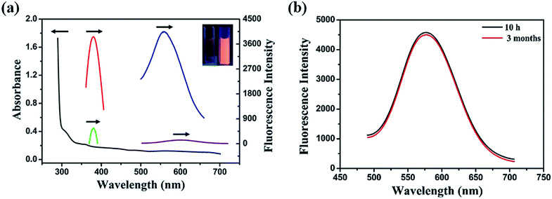
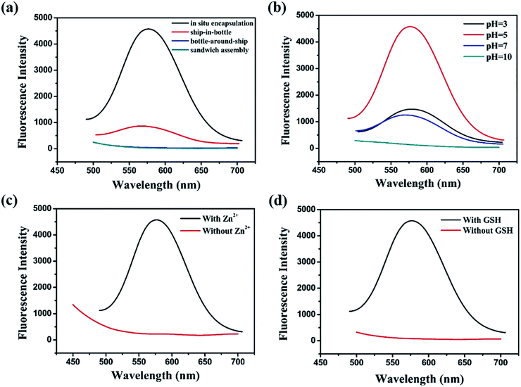
Fabrication process of enhanced fluorescent Cu NCs@GSH/MOF-5 composites by one-pot strategy at room temperature for the first time is seen in Scheme 1. The individual Cu NCs@GSH synthesized according to the reported method exhibit faint fluorescence at 600 nm when excited at 380 nm, shown in Fig. 1a. However, Cu NCs@GSH encapsulated in MOF-5 (Cu NCs@GSH/MOF-5) show strong orange emission at 580 nm with the same excitation wavelength. The intensity is about 35 times than that of individual Cu NCs@GSH. We suspect that the Cu NCs@GSH are encapsulated in the pores of the MOF-5 structure, restricting the vibration of protecting groups on the surface of the Cu NCs@GSH, thus reduce the non-radiation transition. In addition, maybe the confined effect of MOF-5 lead to the predominance of inter-Cu1⋯Cu1 interactions over intra-interactions, resulting in the blue shift of emission wavelength.26 The peak at around 350 nm of UV-vis spectrum, shown in Fig. 1a, is attributed to the interband electronic transition of the Cu NCs. The inexistence of absorption peak at 500–600 nm indicate that Cu NCs, rather than Cu nanoparticles, are encapsulated in MOF-5 successfully. The MOF-5 protects Cu NCs@GSH from being oxidized effectively, thus the stability is extended from 3 days to 3 months (Fig. 1b).It is well known that the sequence of addition of reagents influences the experimental results obviously. Our strategy involves mixing all the necessary constituents at the same time, so it can be attributed to be “in situ encapsulation”. Another three strategies, namely ship-in-bottle, bottle-around-ship and sandwich assembly are performed as well. The “ship-in-bottle” involves the formation of Cu NCs@GSH in the MOFs matrix that have already been formed. On the contrary, the “bottle-around-ship” is to guide the MOF-5 to be assembled around the pre-prepared Cu NCs@GSH. The last one, sandwich assembly, is individual preparation of MOFs and Cu NCs@GSH and subsequent mixing. As shown in Fig. 2a, the products prepared by the “ship-in-bottle” way exhibit weak orange emission at 580 nm and the latter two show hardly any fluorescence. Because the Cu NCs@GSH and MOF-5 must grow under the same reaction conditions, we speculate that pH value is another significant factor in the synthesis process. As shown in Fig. 2b, the intensity of fluorescence reveals obvious difference when the pH values of solution vary at 3, 5, 7 and 10. The fluorescence intensity at pH 5 is about 3 times stronger than others. Theoretically, the alkaline environment is in favor of the crystallization of MOF-5 since it can accelerate the deprotonation of H2BDC, and promote the coordination between H2BDC and Zn2+ to form MOF-5 structure. However, when the pH value is higher than 5, it will severely disrupt the nucleation of Cu NCs@GSH according to the reported literature.6 Considering the intensity of fluorescence of the resulting composites, we chose the pH 5 as the optimum value. In addition, some control experiments have been carried out to confirm the successful synthesis of Cu NCs@GSH/MOF-5 composites. Zn2+ is essential for the formation of MOF-5. The mixture in the absence of Zn2+ is reacted at room temperature for 24 h and purified by the same procedure of the Cu NCs@GSH/MOF-5 composites. As shown in Fig. 2c, the fluorescence intensity without Zn2+ is much lower than that with Zn2+. And the decrease of amount of Zn2+ will result in the reduced fluorescence intensity of Cu NCs@GSH/MOF-5 composites dramatically, shown in Fig. S1.† The mentioned above prove effectively that the Zn2+ in the MOF-5 plays an important role for the enhancement of the optical properties of the Cu NCs@GSH. The addition of Zn2+ not only can enhance the fluorescence intensity of Cu NCs@GSH/MOF-5 but results in the blue shift of emission wavelength compared with that of Cu NCs@GSH. We speculate that Zn2+ has synergetic effect with Cu2+ on the synthesis of Cu NCs@GSH/MOF-5 to some extent. Similarly, in the absence of GSH, as shown in Fig. 2d, there is nearly no fluorescence emission as well. This result illustrates that the capping agent GSH, which can prevent Cu NCs aggregating into larger non-fluorescent nanoparticles, plays a key role in the preparation of fluorescent Cu NCs of the Cu NCs@GSH/MOF-5. The role of each component on the formation of Cu NCs@GSH/MOF-5 have been investigated in more detail, seen in Table S1, Fig. S2 and S3.†
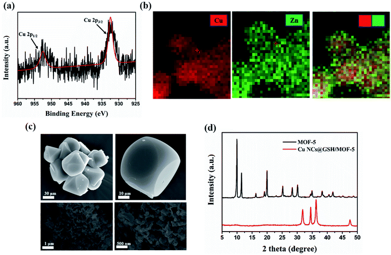
XPS spectrum showed the peaks at 932 eV and 952 eV can be assigned to Cu2p3/2 and Cu2p1/2, which are the characteristic peaks of Cu0, as shown in Fig. 3a. No peak is observed at 942 eV, indicating that there is no Cu2+ in Cu NCs@GSH/MOF-5 composites.27 As shown in Fig. 3b, EDS elemental mapping verifies the uniform distribution of Cu element and demonstrates that Cu NCs@GSH are successfully encapsulated in MOF-5. This is further confirmed by perfectly matching the green and red colour corresponding to Zn and Cu elements shown in an overlapped images. Zn2+ and Cu2+ are distributed uniformly in the Cu NCs@GSH/MOFs and the EDS elemental mapping mainly indicates the qualitative analysis of Zn2+ and Cu2+. As a result, there is no obvious difference in EDS elemental mapping. The specific amount of elementals in the Cu NCs@GSH/MOF-5 composites are showed in Fig. S4.† A series of results above mentioned indicate the successful synthesis of fluorescent Cu NCs@GSH encapsulated into MOF-5. The size and morphology of the as-prepared Cu NCs@GSH/MOF-5 composites are investigated by SEM and TEM, shown in Fig. 3c. The MOF-5 consists of hexahedral structure and the diameter of individual crystal is about 10 μm. On the contrary, the Cu NCs@GSH/MOF-5 composites are composed of abundant randomly nanosheets. This obvious difference in morphology reveals that the introduction of Cu NCs@GSH influences the self-assembly of MOF-5. The Cu NCs@GSH are negatively charged with a zeta potential of −14.6 mV. However, the MOF-5 is positively charged with abundant Zn2+. Therefore, maybe the electrostatic interaction drives Cu NCs@GSH being encapsulated in the pores of MOF-5 shells. Furthermore, TEM image of Cu NCs@GSH/MOF-5, showed in Fig. S5,† exhibits great consistency with the images of SEM, which proves convincingly that the introduction of Cu NCs rather than temperature affects the morphology. The XRD patterns of MOF-5 and Cu NCs@GSH/MOF-5 composites indicate the growth of Cu NCs@GSH and MOF-5 is influenced each other dramatically, shown in Fig. 3d.
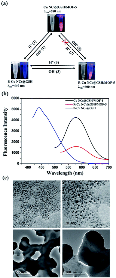
The original Cu NCs@GSH/MOF-5 composites are white turbid liquid with strong orange emission at 580 nm at pH 5. But, the crystal structure of MOF-5 is vulnerable to be destructed in acid solution.28 Upon the addition of HCl solution, MOF-5 is collapsed, which results in the phenomenon that turbid liquid of orange Cu NCs@GSH/MOF-5 turns into transparent solution while the Cu NCs@GSH are exposed directly to the solution, as shown in route H+ (1) in Fig. 4a. When the pH decreases about 3.5, the solution exhibits blue emission at 440 nm. Moreover, the fluorescence intensity is enhanced about 25%, shown in Fig. 4b. The TEM images reveal there is no structure of MOF-5 and the released Cu NCs@GSH show spherical morphology and good dispersibility (Fig. 4c upper). The average diameter of the Cu NCs@GSH is about 2.0 nm by calculating 100 particles. It is obvious that the pH leads to the blue shift of emission wavelength and enhancement of fluorescence intensity of Cu NCs@GSH. This solution is marked as blue-Cu NCs@GSH (B-Cu NCs@GSH). When some NaOH solution was added into B-Cu NCs@GSH, white precipitate reappeared. It indicated the MOF-5 can partially recovered, and orange emission reappeared, seen route OH− (1). If NaOH solution was excess, the solution becomes more turbid. It shows the structure of MOF-5 continued to grow and made the Cu NCs@GSH were much more tightly encapsulated, which lead to the decrease of fluorescence intensity and red shift of fluorescence emission wavelength, marked as red-Cu NCs@GSH/MOF-5 (R-Cu NCs@GSH/MOF-5), as shown in route OH− (2). When pH increases to about 8.5, they show red emission at 600 nm. It meant if NaOH solution was enough, B-Cu NCs@GSH can changed to R-Cu NCs@GSH/MOF-5 directly, as shown in route OH− (3). TEM images indicate that MOF-5 is still hybrided with Cu NCs@GSH in the process of addition of 1 M NaOH solution (Fig. 4c lower). Moreover, the SEM images show that Cu NCs@GSH/MOF-5 exhibit more distinct space structure (Fig. S6†), which is in complete agreement with the more generation of precipitate. However, because the MOF-5 is sensitive with acidic conditions, upon addition of HCl, the structure of MOF-5 in the R-Cu NCs@GSH/MOF-5 would collapse completely to release the Cu NCs, and turn to B-Cu NCs@GSH over the orange Cu NCs@GSH/MOF-5, as shown in route H+ (1) and (3). The dissolution rate of MOF-5 is so fast that the precise control of the appearance of orange fluorescence is difficult (route H+ (2)). In short, Cu NCs@GSH/MOF-5 composites can achieve the inter-conversion of color in acid or base solution, shown in Fig. 4a.
It is important that this one-pot synthetic method can be also extended for the encapsulation of fluorescent Ag NCs in MOF-5 at room temperature owing to the similar properties with Cu. Similarly, the Ag NCs@GSH/MOF-5 composites exhibit strong yellow fluorescence under UV light, shown in Fig. S7a.† The peaks at 368.2 eV and 374.2 eV of XPS spectrum of Ag, shown in Fig. S7b,† are assigned to Ag 3d5/2 and 3d3/2, which indicates the existence of Ag0. The SEM images of a uniform rod-like shape show Ag NCs@GSH/MOF-5 composites have uniform rod-like shape, and the length and width of “stick-like” composites are about 537.9 nm and 81.94 nm, respectively, shown in Fig. S7c.† The almost identical XRD diffraction peaks between MOF-5 and Ag NCs@GSH/MOF-5 composites demonstrate the minor influence of incorporated Ag NCs on the crystal structure of MOF-5, seen Fig. S7d.†
Conclusions
In summary, Cu NCs@GSH and MOF-5 grew in one-pot at the same time while Cu NCs@GSH were distributed homogeneously over the entire MOFs structure. The optical properties and stability of Cu NCs@GSH were improved greatly by the confinement effect of the three-dimensional cavities in the MOF-5. Cu NCs@GSH/MOF-5 displayed conspicuously three fluorescence emission colours depending on the pH values, and the change of fluorescence emission was partially reversible. Since Cu NCs@GSH/MOF-5 composites had high stability, and were easily recycled by centrifugal in aqueous solution, therefore, it would be utilized to develop a reusable sensor for detection of metal ions in the future.Conflicts of interest
There are no conflicts to declare.Acknowledgements
This work was supported by Dalian High Level Talent Innovation Support Programme (Grant No. 2015R043), the Fundamental Research Funds for the Central Universities (Grant No. DUT16LK09), the Open Funds of the State Key Laboratory of Electroanalytical Chemistry (Grant No. SKLEAC201608) and Changjiang Scholars Program (Grant No. T2012049).References
- D. Li, Z. Chen and X. Mei, Adv. Colloid Interface Sci., 2017, 250, 25–39 CrossRef PubMed.
- Y. L. Xiaohui Gao, M. Liu, S. He and W. Chen, J. Mater. Chem. C, 2016, 3, 4050–4056 Search PubMed.
- G. Zhang, T. Xu, H. Du, Y. Qiao, X. Guo, L. Shi, Y. Zhang, S. Shuang, C. Dong and H. Ma, J. Mater. Chem. C, 2016, 4, 3540–3545 RSC.
- D. Li, Z. Chen, Z. Wan, T. Yang, H. Wang and X. Mei, RSC Adv., 2016, 6, 34090–34095 RSC.
- Y. E. Shi, S. Luo, X. Ji, F. Liu, X. Chen, Y. Huang, L. Dong and L. Wang, Dalton Trans., 2017, 46, 14251–14255 RSC.
- L. Lin, Y. Hu, L. Zhang, Y. Huang and S. Zhao, Biosens. Bioelectron., 2017, 94, 523–529 CrossRef PubMed.
- T. Luo, S. Zhang, Y. Wang, M. Wang, M. Liao and X. Kou, Luminescence, 2017, 32, 1092–1099 CrossRef PubMed.
- B. Han, X. Hou, R. Xiang and G. He, Anal. Methods, 2017, 9, 4028–4032 RSC.
- J. Xu and B. Han, Nano, 2016, 11, 1650108 CrossRef.
- J. R. Bhamore, S. Jha, A. K. Mungara, R. K. Singhal, D. Sonkeshariya and S. K. Kailasa, Biosens. Bioelectron., 2016, 80, 243–248 CrossRef PubMed.
- C. Wang, H. Cheng, Y. Huang, Z. Xu, H. Lin and C. Zhang, Analyst, 2015, 140, 5634–5639 RSC.
- S. Yang, X. Sun and Y. Chen, Mater. Lett., 2017, 194, 5–8 CrossRef.
- D. Li, Y. Zhao, Z. Chen, X. Mei and X. Qiu, Mater. Sci. Eng. C, 2017, 78, 653–657 CrossRef PubMed.
- J. V. Morabito, L. Y. Chou, Z. Li, C. M. Manna, C. A. Petroff, R. J. Kyada, J. M. Palomba, J. A. Byers and C. K. Tsung, J. Am. Chem. Soc., 2014, 136, 12540–12543 CrossRef PubMed.
- Y. Wen, T. Sheng, X. Zhu, C. Zhuo, S. Su, H. Li, S. Hu, Q. L. Zhu and X. Wu, Adv. Mater., 2017, 29, 1700778 CrossRef PubMed.
- T. Kitao, M. W. A. MacLean, B. Le Ouay, Y. Sasaki, M. Tsujimoto, S. Kitagawa and T. Uemura, Polym. Chem., 2017, 8, 5077–5081 RSC.
- J. Zhuang, A. P. Young and C. K. Tsung, Small, 2017, 13, 1700880 CrossRef PubMed.
- L. Chen, R. Luque and Y. Li, Chem. Soc. Rev., 2017, 46, 4614–4630 RSC.
- J. Yu, L. H. Xie, J. R. Li, Y. Ma, J. M. Seminario and P. B. Balbuena, Chem. Rev., 2017, 117, 9674–9754 CrossRef PubMed.
- Y. Guan, J. Shi, M. Xia, J. Zhang, Z. Pang, A. Marchetti, X. Wang, J. Cai and X. Kong, Appl. Surf. Sci., 2017, 423, 349–353 CrossRef.
- F. G. Cirujano, I. Luz, M. Soukri, C. Van Goethem, I. F. J. Vankelecom, M. Lail and D. E. De Vos, Angew. Chem., 2017, 56, 13302–13306 CrossRef PubMed.
- G. L. a. J. T. Hupp, J. Am. Chem. Soc., 2010, 132, 7832–7833 CrossRef PubMed.
- F. Cao, E. Ju, C. Liu, W. Li and Y. Zhang, Nanoscale, 2017, 9, 4128–4134 RSC.
- D. A. Islam, A. Chakraborty and H. Acharya, New J. Chem., 2016, 40, 6745–6751 RSC.
- Z. Wang, R. Chen, Y. Xiong, K. Cepe, J. Schneider, R. Zboril, C.-S. Lee and A. L. Rogach, Part. Part. Syst. Charact., 2017, 34, 1700029 CrossRef.
- J. Liu, Q. M. Zhang, Y. Feng, Z. Zhou and K. Shih, Chemphyschem, 2016, 17, 225–231 CrossRef PubMed.
- X. Hu, T. Liu, Y. Zhuang, W. Wang, Y. Li, W. Fan and Y. Huang, TrAC, Trends Anal. Chem., 2016, 77, 66–75 CrossRef.
- S. Han and M. S. Lah, Cryst. Growth Des., 2015, 15, 5568–5572 CrossRef.
Footnote |
| † Electronic supplementary information (ESI) available. See DOI: 10.1039/c8ra03632b |
| This journal is © The Royal Society of Chemistry 2018 |

