 Open Access Article
Wearable triboelectric nanogenerators based on hybridized triboelectric modes for harvesting mechanical energy†
Yu Qiu *ac,
Dechao Yang*b,
Bing Lia,
Shuai Shaoa and
Lizhong Huac
aSchool of Physics, Dalian University of Technology, Dalian 116024, People’s Republic of China. E-mail: yuqiu@dlut.edu.cn
bDepartment of Electronic Engineering, Dalian Neusoft University of Information, Dalian, 116024, People’s Republic of China. E-mail: yangdechao@neusoft.edu.cn
cThe Key Laboratory for Micro/Nano Technology and System of Liaoning Province, Dalian University of Technology, Dalian 116024, People’s Republic of China
First published on 23rd July 2018
Abstract
In this paper, we demonstrate a newly designed hybridized triboelectric nanogenerator (TENG) fabric incorporating multiple working modes, which can effectively harvest ambient mechanical energy for conversion into electric power by working in a hybridization of a contact–separation mode, a sliding mode and a freestanding triboelectric layer mode. The power generation of each mode of the TENG fabric was systematically investigated and compared along different directions, under different frequencies and at different locations. Owing to the advanced structural design, the as-fabricated TENG fabric could be switched between multiple working modes according to its real working situation. High output voltage and current of about 140 V and 0.6 μA, respectively, were obtained from a larger size of TENG fabric, which could be used to light up 120 LEDs in series. Compared to the previously reported TENGs, such a hybridized TENG fabric based on hybridized modes has much better adaptability for harvesting energy (such as human walking, running, and other human motion) in different directions. This work presents the promising potential of hybridized TENG fabric for power generation and self-powered wearable devices.
1. Introduction
Wearable electronic devices have received great attention due to their promising applications in a vast range of fields such as health monitoring, wearable smart phones, artificial skin sensors and motion tracking.1–9 Typically, any of these electronic devices need an external power source to operate. However, traditional rigid batteries as power sources remain a bottleneck hindering the practical and sustainable uses of wearable electronics, due to their heavy weight, bulky volume, and limited capacity and lifetime. In order to improve the flexibility of the battery, the development of new technologies that can harvest energy from the environment as sustainable self-powered sources has become a newly emerging field.10–12Triboelectric nanogenerators (TENGs) have been invented as an effective way to harvest energy from our living environment (such as human motion, flowing water and airflow) based on the coupling of contact-electrification and electrostatic induction.13–16 Since 2012, TENGs have been successfully demonstrated as promising energy-harvesting technology for self-powered devices, such as motion tracking systems, velocity sensors, biosensors and so on,9,17–21 due to their cost-effectiveness, high efficiency, low-cost, environmental friendliness, and universal availability.22–25 Very recently, attempts have been made to fabricate fabric-based TENGs for promising applications in self-powered wearable electronics.26–28 For example, Zhou et al.29 reported a woven structured TENG based on a freestanding triboelectric-layer mode for scavenging energy from human motion, which showed a stable output voltage and current of about 10–30 V and 0.5–1 μA, respectively. Pu et al.28 have demonstrated a wearable fabric TENG by using a grating-structure which could convert low-frequency human motion energy into high-frequency electrical outputs. However, these structural designs of TENGs can only work in 1D or 2D directions, and are unable to harvest mechanical energy from arbitrary directions, which largely limits their versatility and applicability in wearable electronics, because of the variability of human movement. Further research is still urgently required to design fabric-based TENGs that have 3D motion energy scavenging abilities for maximizing energy harvesting. Meanwhile, integration of fabric-based TENGs that incorporate different modes (including a contact mode, a sliding mode and a freestanding triboelectric mode) has seldom been found in literature, though several works have been reported of TENGs integrated with other energy harvesters (such as solar cells). It is desirable to incorporate two or more modes that can be integrated together, giving the device the ability to collect either sliding movement or separation movement according to the actual conditions, which has much better adaptability in wearable electronics.
Herein, we demonstrate a hybridized TENG fabric incorporating different working modes (including a contact–separation mode, a sliding mode and a freestanding triboelectric-layer mode), each mode of which can be used effectively and in a complementary manner. The working principles were analyzed in order to fully understand the power generating process of each TENG fabric. The output performance of each mode was systematically investigated under different directions, frequencies, and locations. Additionally, the TENG fabric was also employed in applications for lighting up commercial LED bulbs.
2. Experimental section
2.1 Fabrication of the grid-patterned Au-coated fabric (G-fabric)
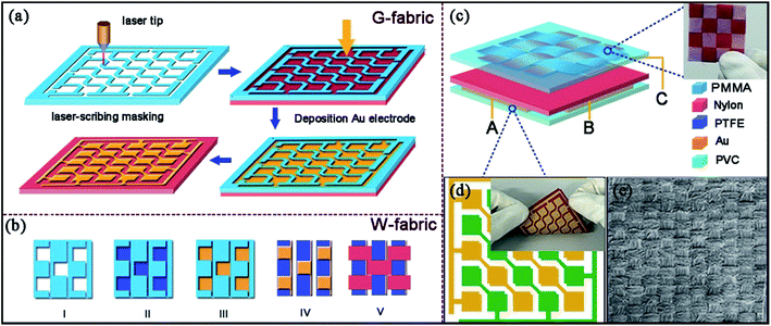
Here, a piece of nylon fabric (60 × 60 mm2) and a PMMA board were used as the starting substrates. The detailed fabrication process of the grid-patterned electrode is shown in Fig. 1a. First, laser-scribing equipment was utilized to obtain a PMMA laser-scribed mask, with the size of a single square window of about 8 × 8 mm2; for fabricating the grid-patterned electrode coated fabric, the scribed PMMA mask was covered onto the reverse side of the prepared nylon fabric, and a 50 μm-thick Au layer was deposited onto the nylon fabric by ion sputtering equipment. Then, two conducting copper wires were connected to each of the Au electrodes by aluminum tape, serving as the electrodes A and B, respectively. Finally, a PVC layer was covered on the back grid-patterned side of the Au electrode, acting as a protective layer.2.2 Fabrication of the woven-structured triboelectric fabric (W-fabric)
The fabrication process of the woven-structured triboelectric fabric (W-fabric) is illustrated in Fig. 1b. Here, nylon fabric and PTFE film were chosen for the W-fabric. First, they were cut into strips (8 mm in width and 25–60 mm in length), then laser-scribing masking and ion sputtering equipment were reused to fabricate patterned conductive circuits on the PTFE strips as shown in Fig. 1b. The W-fabric was woven by using Au-coated PTFE and nylon strips as longitudes and latitudes, respectively. Last, a lead wire was connected to the Au-coated PTFE strips by aluminum tape, which served as electrode C.2.3 Measurement of the TENG fabric
The surface of Au-coated nylon fabric was characterized by using scanning electron microscopy (SEM; FEI Nova Nano-SEM). For convenience of measurement, the as-fabricated G-fabric, with the Au electrodes side facing down, was adhered onto a large piece of acrylic plate (15 × 15 cm2) that acted as a supporting substrate. The short-circuit current of the TENG was measured using a low noise current preamplifier. And the open-circuit voltage was measured by using a Keithley 4200 semiconductor characterization system.3. Result and discussion
3.1 Structure design of the hybridized TENG fabric
The hybridized TENG fabric was structurally composed of two parts: one part was the woven-structured fabric (W-fabric); and the other part was the nylon fabric with a grid-patterned back electrode (G-fabric), as shown in Fig. 1c. In general, the hybridized TENG fabric had two basic structures: one was a free-standing TENG (named FS-TENG), in which the structured grid-patterned electrodes A and B were chosen as the terminals, and the top W-fabric acted as the freestanding triboelectric layer. The other structure was a contact–separation type TENG (named CS-TENG) where electrodes A and B were connected together and acted as one of the terminals, and electrode C acted as another terminal. The photograph and corresponding scanning electron microscopy (SEM) image of the grid-patterned Au electrode on nylon are shown in Fig. 1d and e, demonstrating its flexibility and electrode continuity. The proposed hybridized TENG could be easily integrated to human clothes, because of its flexibility, wearability, and air permeability.3.2 Working mechanisms and output performances of the TENGs
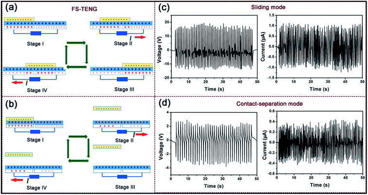
Because of the complexity of human motion, both FS-TENG and CS-TENG have at least two modes of movement, one being pressing and the other sliding. In order to harvest mechanical energy in different directions, our TENGs were designed to work in both a contact–separation mode and a sliding mode simultaneously. To fully understand the power generating process of the TENG fabrics, each mode of the TENG fabrics was carefully analyzed.Fig. 2a shows the scheme of the FS-TENG fabric in a contact–separation mode motion. For the sliding mode, as the top W-fabric contacts with the G-fabric, because PTFE and nylon fabrics have different abilities in attracting electrons, there are positive triboelectric charges on the nylon surface and negative ones on the PTFE surface (Fig. 2a stage I). When the W-fabric starts to slide toward the right-hand side, the induced negative charges on the top triboelectric layer (PTFE) result in an instantaneous electron flow from electrode B to electrode A, finally reaching equilibrium when the W-fabric stops on the right side of the nylon (Fig. 2a stage III). Once it moves back from the right side to the left side, the electrons flow back from electrode A to electrode B, until another equilibrium is achieved30,31 (Fig. 2a stage IV). For the contact–separation mode, when they are separated, an electric potential difference is produced, driving electrons to flow from electrode B to electrode A through an external circuit in order to balance the generated triboelectric potential (Fig. 2b stage II). As the separation between the W-fabric and the G-fabric is maximized, the flow of electrons is stopped because an electrostatic equilibrium is reached (Fig. 2b stage II); once the W-fabric is driven to contact with the nylon layer again, electrons flow from electrode A back to electrode B, until another equilibrium is achieved (Fig. 2b stage II).
Subsequently, the output performances of FS-TENG in both working modes were also evaluated. For the sliding mode, the open-circuit voltage (VOC), and the short-circuit current (Isc) are shown in Fig. 2c and d, with peak values of around 15 V and 1 μA, respectively. Meanwhile, the output performance of FS-TENG in the contact–separation mode was also characterized in the sliding mode. As exhibited in Fig. 2, the values of the open-circuit voltage (VOC), and the short-circuit current (Isc) were 2 V and 0.3 μA, and were smaller than those in the sliding mode. We can see that by having a freestanding triboelectric layer (W-fabric), FS-TENG could move freely without any constraint. Moreover, FS-TENG in the sliding mode also had the capability of converting low-frequency motion into high-frequency signals, i.e. each sliding motion generated multiple peaks rather than one single peak, as was observed for the previous reported TENG, which will largely expand the applications of TENGs for versatile mechanical energy harvesting, especially for wearable devices.
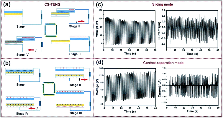
Similarly, the energy-harvesting of the CS-TENG fabric is also schematically illustrated in Fig. 3. Because of the large differences in the ability to attract electrons, the triboelectrification left the nylon surface with positive charges and the PTFE with net negative charges with equal density. For the sliding mode, once the top W-fabric slides outward (Fig. 3a stage II), the induced potential difference drives a current to flow from electrode A(B) to electrode C through an external circuit in order to balance the generated triboelectric potential. Subsequently, when the W-fabric was slid backward (Fig. 3a stage IV), the separated charges began to get in contact again, and the redundant charge transferred electrons flowed back through an external circuit, resulting in a current flow from electrode C to electrode A(B).13,32 For the contact–separation mode of CS-TENG, when the W-fabric is separated from the nylon surface, the induced potential drives a current to flow from electrode A(B) to electrode C until the potential difference is fully offset by the transferred charges (Fig. 3b stage II); when the W-fabric is reverted to contact the nylon surface again, electrons flow back from electrode C to electrode A(B), until another equilibrium is achieved (Fig. 3b stage II).33
The output performances of CS-TENG both in the sliding and contact–separation working modes were measured as shown in Fig. 3c and d. For the sliding mode, the VOC was measured to be about 120 VOC and the Isc was measured to be about 0.6 μA. It is noteworthy that in this mode, electric signals are only generated when the W-fabric slides out of the T-fabric; i.e. there is little output when the W-fabric slides only inside the G-fabric (as shown in Fig. S1†), which is because there is no polarization generated in this case.33 For the contact–separation mode of CS-TENG, the measured VOC and Isc were about 120 V and 0.8 μA. It can seen be that both modes of CS-TENG have higher output performances than those of FS-TENG.
3.3 Influencing factors on the TENG fabric
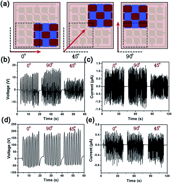
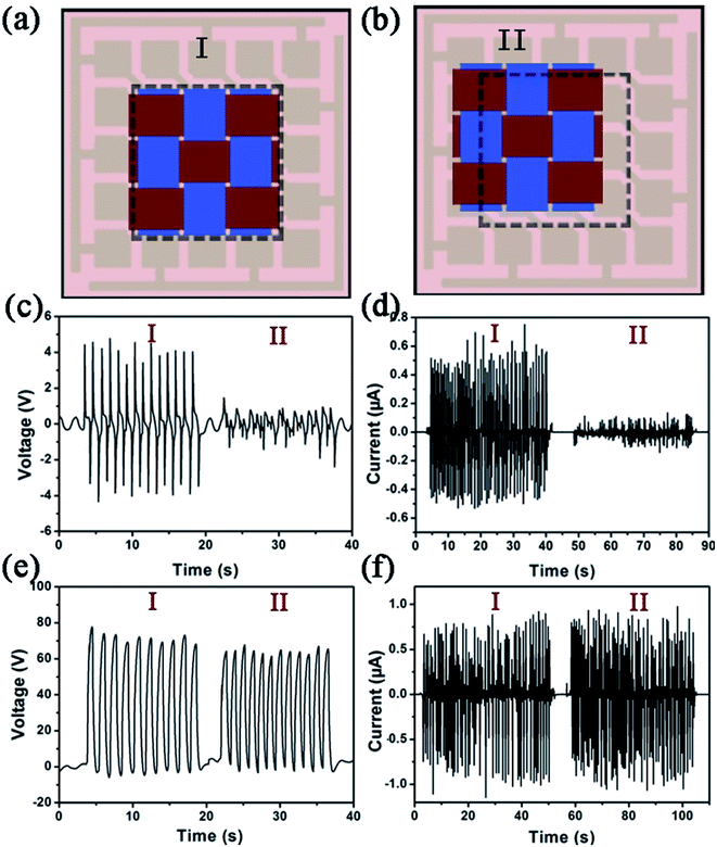
Since the mechanical energy from the environment is always irregular and varies in frequency, it is necessary to study the dependence of the TENGs’ outputs on motion-direction. For the sliding mode, both output performances of FS-TENG and CS-TENG working along three typical directions (0°, 45° and 90°) were investigated for contrast. For FS-TENG, when the W-fabric slid along 0° and 90°, the output voltage and current remained unchanged (15 V and 1 μA) (as shown in Fig. 4); while when the sliding angle was 45°, the output voltage and current were decreased slightly from 15 V and 1 μA to 8 V and 0.5 μA, respectively. Fig. 4d–e show the corresponding output signals of CS-TENG sliding along 0°, 45° and 90°. From Fig. 4, we can see that CS-TENG can harvest sliding energy from all directions with the output performance remaining almost unchanged. In this case, the grid-patterned Au electrodes were perceived as a whole because A and B were connected together. Therefore, the sliding path does not have a big impact on the output performance. For the contact–separation mode, the contrasting output performances of FS-TENG and CS-TENG under different contact–separation positions were measured as shown in Fig. 5. We can see that when the W-fabric and the G-fabric changed contact–separation points from the matched style I (where the W-fabric matched exactly with the grid-patterned electrodes below) to the unmatched style II (where the W-fabric was unmatched with the grid-patterned electrodes below), both the output voltage and the current of FS-TENG decreased greatly from 4 V and 0.5 μA to 0.5 V and 0.1 μA, respectively. While, for CS-TENG, the output performance was almost constant when changing the contact–separation points, as shown in Fig. 5e and f.From the results above, we can easily see that CS-TENG shows more excellent advantages, not only because of its higher output performance, but also because it is basically not affected by the influence of movement direction, including the sliding path or the contact–separation point, which might mean it has much better adaptability for harvesting energy. However, FS-TENG also has its advantages in unique working situations. For example, FS-TENG could have the ability of harvesting small amplitude sliding mechanical movements; while CS-TENG can only collect large amplitude motions, because no signal is generated when the W-fabric slides only inside the G-fabric. Therefore, the as-fabricated hybridized TENG fabric could be switched between both structures, according to the real working situation, by changing the connection.
Besides the motion-direction, another factor that could influence the output of the TENGs is the frequency. As a supplement, the relationship between the electrical outputs of the TENGs and the frequency was systematically investigated as shown in Fig. S2.† As for the VOC, the peak value remained almost unchanged under different frequencies (f1 < f2 < f3). According to the previous reports, the VOC is independent to the sliding velocity, and is only determined by the displacement.33 As for the Isc, the peak heights for the four working modes present an obvious increasing trend with increased frequency (f1 < f2 < f3), because higher frequency will not only result in more transferred charges as discussed before, but also more importantly contributes to a higher charge transfer rate.
High output performances can be achieved by the TENG fabric with a large segment size. Here, a larger laser-scribed mask, with a single square window with size of about 20 × 20 mm2, was also utilized to obtain a larger piece of TENG fabric with dimensions of 5 × 5 mm2. The performances of both the FS-TENG and the CS-TENG fabrics were tested under both the sliding mode for FS-TENG and the contact–separation mode for CS-TENG. Fig. 6a and b display typical output signals of FS-TENG in the sliding mode, which delivers a maximum output voltage of 140 V, and a maximum output current of 0.6 μA, respectively. Through the use of a full-wave bridge rectifier, the energy harvesting capability of the FS-TENG fabric was also evaluated under the sliding mode for charging three commercial capacitors (2.2 μF, 3.3 μF and 10 μF, respectively) in a direct charge cycle. With a similar frequency of ∼0.5 Hz, three commercial capacitors can be charged from 0 to 850 mV (black line), 600 mV and 400 mV (red line), respectively, within 25 s as shown in Fig. 6c. Furthermore, a total of 120 commercial LED bulbs were assembled in series on a piece of electrical circuit board (Fig. 6d), and were connected to the TENG fabric. When manually triggered, both the FS-TENG and the CS-TENG fabrics could directly and simultaneously light up all of these 120 LED bulbs. (ESI Videos 1 and 2†). This demonstration suggested that the TENG fabrics have potential as sustainable power sources for driving wearable smart electronics.
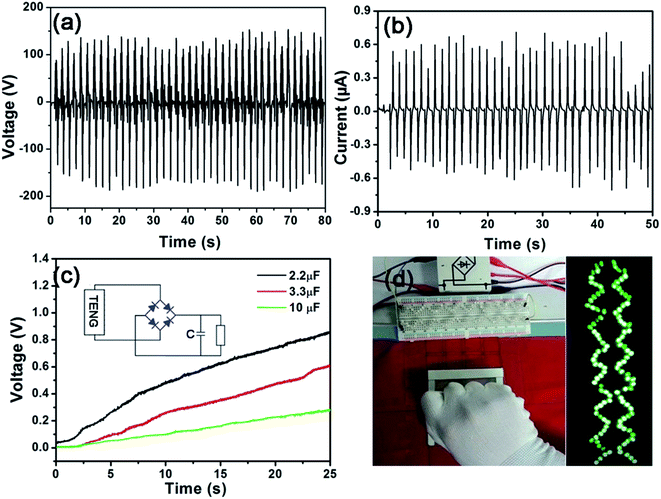 | ||
| Fig. 6 (a and b) Typical output performances of the FS-TENG fabric with a larger size working in the sliding mode. (c) Charging curves of three capacitors (2.2 μF, 3.3 μF and 10 μF) charged by the FS-TENG fabric under the sliding mode. The inset is the equivalent electrical circuit of the self-charging power system. (d) A snapshot of the 120 commercial LED bulbs in serial-connection directly driven by the FS-TENG fabric under the sliding mode. (An equivalent snapshot of the CS-TENG fabric is shown in the ESI†). | ||
4. Conclusion
In this paper, the concept of a hybridized energy harvester incorporating different modes (including a contact mode, a sliding mode and a freestanding triboelectric mode) was proposed, so that each mode could be used effectively and in a complementary manner in a TENG fabric. The working principle of each mode of the TENG fabric was analyzed in order to fully understand the power generation process. The power generation of each mode was systematically investigated and compared along different directions, under different frequencies, and in different locations. A typical TENG fabric with a larger size can deliver a maximum output voltage of 140 V, a maximum output current of 0.6 μA, which can be used to light up 120 LEDs. Compared to the previously reported TENGs, such a hybridized TENG fabric, based on hybridized modes, has much better adaptability for harvesting energy (such as human walking, running, and other human motion) in different directions.Conflicts of interest
There are no conflicts to declare.Acknowledgements
This work was supported by the NSFC (Project No. 61504018), the Doctoral Scientific Research Foundation of Liaoning Province (Project No. 201501193), Training Program of Innovation and Entrepreneurship for Undergraduates of DUT (201710141100040874), General Project of Scientific Research of the Education Department of Liaoning Province (L2015040), and Support high-level innovative entrepreneurial talent project in Dalian (2015R094). Foundation of Key laboratory for Micro/Nano Technology and System of Liaoning and Province (20140405).References
- W. Gao, S. Emaminejad, H. Y. Y. Nyein, S. Challa, K. Chen, A. Peck, H. M. Fahad, H. Ota, H. Shiraki and D. Kiriya, Fully integrated wearable sensor arrays for multiplexed in situ perspiration analysis, Nature, 2016, 529(7587), 509–514 CrossRef PubMed.
- M. J. Cima, Next-generation wearable electronics, Nat. Biotechnol., 2014, 32(7), 642–643 CrossRef PubMed.
- S. Choi, H. Lee, R. Ghaffari, T. Hyeon and D. H. Kim, Recent Advances in Flexible and Stretchable Bio-Electronic Devices Integrated with Nanomaterials, Adv. Mater., 2016, 28(22), 4203–4218 CrossRef PubMed.
- Y. Khan, A. E. Ostfeld, C. M. Lochner, A. Pierre and A. C. Arias, Monitoring of vital signs with flexible and wearable medical devices, Adv. Mater., 2016, 28(22), 4373–4395 CrossRef PubMed.
- T. Yokota, P. Zalar, M. Kaltenbrunner, H. Jinno, N. Matsuhisa, H. Kitanosako, Y. Tachibana, W. Yukita, M. Koizumi and T. Someya, Ultraflexible organic photonic skin, Sci. Adv., 2016, 2(4), e1501856 Search PubMed.
- T. Sekitani, U. Zschieschang, H. Klauk and T. Someya, Flexible organic transistors and circuits with extreme bending stability, Nat. Mater., 2010, 9(12), 1015–1022 CrossRef PubMed.
- M. S. White, M. Kaltenbrunner, E. D. Głowacki, K. Gutnichenko, G. Kettlgruber, I. Graz, S. Aazou, C. Ulbricht, D. A. M. Egbe and M. C. Miron, Ultrathin, highly flexible and stretchable PLEDs, Nat. Photonics, 2013, 7(10), 811–816 CrossRef.
- S. C. Mannsfeld, B. C. Tee, R. M. Stoltenberg, C. V. Chen, S. Barman, B. V. Muir, A. N. Sokolov, C. Reese and Z. Bao, Highly sensitive flexible pressure sensors with microstructured rubber dielectric layers, Nat. Mater., 2010, 9(10), 859 CrossRef PubMed.
- P. Xiong, M. Liu, X. Chen, J. Sun, C. Du, Z. Yang, J. Zhai, W. Hu and L. W. Zhong, Ultrastretchable, transparent triboelectric nanogenerator as electronic skin for biomechanical energy harvesting and tactile sensing, Sci. Adv., 2017, 3(5), 1–10 Search PubMed.
- Z. L. Wang, Self-Powered Nanosensors and Nanosystems, Adv. Mater., 2012, 24(2), 280–285 CrossRef PubMed.
- K. Parida, V. Bhavanasi, V. Kumar, J. Wang and P. S. Lee, Fast charging self-powered electric double layer capacitor, J. Power Sources, 2017, 342, 70–78 CrossRef.
- Z. L. Wang, Towards Self-Powered Nanosystems: From Nanogenerators to Nanopiezotronics, Adv. Funct. Mater., 2008, 18(22), 3553–3567 CrossRef.
- F. R. Fan, Z. Q. Tian and Z. L. Wang, Flexible triboelectric generator, Nano Energy, 2012, 1(2), 328–334 CrossRef.
- F. R. Fan, W. Tang and Z. L. Wang, Flexible Nanogenerators for Energy Harvesting and Self-Powered Electronics, Adv. Mater., 2016, 28(22), 4283 CrossRef PubMed.
- H. Wu, Y. Huang, F. Xu, Y. Duan and Z. Yin, Energy Harvesters for Wearable and Stretchable Electronics: From Flexibility to Stretchability, Adv. Mater., 2016, 28(45), 9881 CrossRef PubMed.
- R. Hinchet, W. Seung and S. W. Kim, Recent Progress on Flexible Triboelectric Nanogenerators for Selfpowered Electronics, ChemSusChem, 2015, 8(14), 2327 CrossRef PubMed.
- C. B. Han, C. Zhang, X. H. Li, L. Zhang, T. Zhou, W. Hu and Z. L. Wang, Self-powered velocity and trajectory tracking sensor array made of planar triboelectric nanogenerator pixels, Nano Energy, 2014, 9(9), 325–333 CrossRef.
- J. Chen, P. Ding, R. Pan, W. Xuan, D. Guo, Z. Ye, W. Yin, H. Jin, X. Wang and S. Dong, Self-powered transparent glass-based single electrode triboelectric motion tracking sensor array, Nano Energy, 2017, 442–448 CrossRef.
- F. R. Fan, L. Lin, G. Zhu, W. Wu, R. Zhang and Z. L. Wang, Transparent triboelectric nanogenerators and self-powered pressure sensors based on micropatterned plastic films, Nano Lett., 2012, 12(6), 3109 CrossRef PubMed.
- Y. Yang, L. Lin, Y. Zhang, Q. Jing, T. C. Hou and Z. L. Wang, Self-Powered Magnetic Sensor Based on a Triboelectric Nanogenerator, ACS Nano, 2012, 6(11), 10378 CrossRef PubMed.
- H. Zhang, Y. Yang, T. C. Hou, Y. Su, C. Hu and Z. L. Wang, Triboelectric nanogenerator built inside clothes for self-powered glucose biosensors, Nano Energy, 2013, 2(5), 1019–1024 CrossRef.
- Y. Zi, S. Niu, J. Wang, Z. Wen, W. Tang and Z. L. Wang, Standards and figure-of-merits for quantifying the performance of triboelectric nanogenerators, Nat. Commun., 2015, 6, 8376 CrossRef PubMed.
- X. He, Y. Zi, H. Guo, H. Zheng, Y. Xi, C. Wu, J. Wang, W. Zhang, C. Lu and Z. L. Wang, A Highly Stretchable Fiber-Based Triboelectric Nanogenerator for Self-Powered Wearable Electronics, Adv. Funct. Mater., 2017, 27(4), 1604378 CrossRef.
- Z. Zhao, X. Pu, C. Du, L. Li, C. Jiang, W. Hu and Z. L. Wang, Freestanding Flag-Type Triboelectric Nanogenerator for Harvesting High-Altitude Wind Energy from Arbitrary Directions, ACS Nano, 2016, 10(2), 1780 CrossRef PubMed.
- U. Khan and S. W. Kim, Triboelectric Nanogenerators for Blue Energy Harvesting, ACS Nano, 2016, 10(7), 6429–6432 CrossRef PubMed.
- F. Yi, J. Wang, X. Wang, S. Niu, S. Li, Q. Liao, Y. Xu, Z. You, Y. Zhang and Z. L. Wang, Stretchable and Waterproof Self-Charging Power System for Harvesting Energy from Diverse Deformation and Powering Wearable Electronics, ACS Nano, 2016, 10(7), 6519 CrossRef PubMed.
- J. Wang, S. Li, F. Yi, Y. Zi, J. Lin, X. Wang, Y. Xu and Z. L. Wang, Sustainably powering wearable electronics solely by biomechanical energy, Nat. Commun., 2016, 7, 12744 CrossRef PubMed.
- X. Pu, W. Song, M. Liu, C. Sun, C. Du, C. Jiang, X. Huang, D. Zou, W. Hu and Z. L. Wang, Wearable Power-Textiles by Integrating Fabric Triboelectric Nanogenerators and Fiber-Shaped Dye-Sensitized Solar Cells, Adv. Energy Mater., 2016, 6(20), 1601048 CrossRef.
- T. Zhou, C. Zhang, C. B. Han, F. R. Fan, W. Tang and Z. L. Wang, Woven structured triboelectric nanogenerator for wearable devices, ACS Appl. Mater. Interfaces, 2014, 6(16), 14695–14701 CrossRef PubMed.
- S. Wang, Y. Xie, S. Niu, L. Lin and Z. L. Wang, Freestanding triboelectric-layer-based nanogenerators for harvesting energy from a moving object or human motion in contact and non-contact modes, Adv. Mater., 2014, 26(18), 2818–2824 CrossRef PubMed.
- S. Niu, Y. Liu, X. Chen, S. Wang, Y. S. Zhou, L. Lin, Y. Xie and Z. L. Wang, Theory of freestanding triboelectric-layer-based nanogenerators, Nano Energy, 2015, 12, 760–774 CrossRef.
- S. Wang, L. Lin and Z. L. Wang, Nanoscale triboelectric-effect-enabled energy conversion for sustainably powering portable electronics, Nano Lett., 2012, 12(12), 6339 CrossRef PubMed.
- S. Wang, L. Lin, Y. Xie, Q. Jing, S. Niu and Z. L. Wang, Sliding-triboelectric nanogenerators based on in-plane charge-separation mechanism, Nano Lett., 2013, 13(5), 2226 CrossRef PubMed.
Footnote |
| † Electronic supplementary information (ESI) available. See DOI: 10.1039/c8ra03677b |
| This journal is © The Royal Society of Chemistry 2018 |

