 Open Access Article
Porous three-dimensional network of Pd–Cu aerogel toward formic acid oxidation
Abdollatif Shafaei Douk *,
Majid Farsadrooh
 ,
Farzane Damanigol,
Alireza Ansari Moghaddam,
Hamideh Saravani
 * and
Meissam Noroozifar
Department of Chemistry, University of Sistan and Baluchestan, P. O. Box 98135-674, Zahedan, Iran. E-mail: shafaeidouk@pgs.usb.ac.ir; saravani@chem.usb.ac.ir
First published on 28th June 2018
Abstract
New self-assembled architectures have received great interest in nanotechnology, and are a highly desired target in recent studies. Among self-assembled architectures, noble metal aerogels are an important class owing to their collective characters as well as widespread applications. The synthesis of noble metal aerogels still faces several obstacles such as long hydrogel creation time and complicated multistep strategies. In this paper, we propose an efficient and useful approach to create the three-dimensional network of a Pd–Cu aerogel. This way offers a number of advantages including one-pot synthesis, simplicity, and short time to prepare the hydrogel. The Pd–Cu aerogel was prepared by the reduction of H2PdCl4 and CuCl2 in the presence of sodium carbonate by using glyoxylic acid monohydrate as a reducing agent followed by supercritical CO2 drying. The Pd–Cu aerogel was applied as an anode catalyst for electrooxidation process of formic acid, and depicts much higher electrocatalytic activity and durability compared to the Pd/C. We believe that the exceptional three-dimensional nanostructures fabricated by this route are powerful and promising catalysts for application in direct formic acid fuel cells (DFAFCs), which may open great opportunities for widespread applications such as catalysis, sensors, optoelectronics, electrochemical energy systems, etc.
Introduction
Direct formic acid fuel cells (DFAFCs) have sparked extensive attention on account of their safe storage, low toxicity, low operating temperature, security, high energy density and low pollutant emission.1–3 However, the application of DFAFCs at the commercial level still faces several vital obstacles such as low performance, inadequate stability and the expensive of catalysts. To resolve these problems, a variety of approaches have been published based on the tailored design of the size, chemical compositions, and shape of a catalyst.4–15Nowadays, self-assembled architectures have attracted great attention in nanoscience on account of their widespread applications (e.g. sensors, optics, catalysis, etc.). Self-assembly processes display excellent strategies for the creation of unique structures. Until now, self-assembled architectures were employed for the fabrication of one-dimensional (1D), two-dimensional (2D) and three-dimensional (3D) porous materials. The tailored engineering of these nanomaterials with extended surfaces (e.g. nanowires, nanosheets, nanosponges, etc.) has provided enormous opportunities for the improvement of their electrocatalytic behaviour and stability.16 Among them, metal aerogels with exceptional structures have appeared as state-of-the-art catalysts.
Aerogels are unique solid materials with extremely low densities, high porosity, and high specific surface areas.17–19 They are porous 3D networks, which are usually a result of self-assembly of nanoparticles (NPs). Metal NPs act as the building units to fabricate the 3D nanostructures with unique properties.20 These porous metal nanostructures not only combine the physical and chemical properties of nanomaterials with those of the macroscale, but also possess attractive unique properties in terms of their composition, size, and morphological effect. Moreover, the aerogels not only offer common properties of aerogels such as high specific surface area, extremely low density and porosity, but also contain unique properties of metals such as considerable thermal and electrical conductivity, catalytic performance, etc.17–19 These unique porous 3D nanostructures mainly have two advantages: (1) the self-supporting character of these porous 3D nanostructures may hinder the loss of stability observed in carbon supported metal catalysts caused by corrosion, and (2) the macroporous 3D network offers high specific active surface area, and leads to easier accessibility of the reactant molecules to the active sites, and improvement of the catalytic activities.12–14 Based on the mentioned characters, these exceptional structures are excellent supportless catalysts for application in fuel cells.
In 1931, Kistler et al. pioneered the first aerogels synthesis (silica and alike).21 Since then, a lot of studies have been dedicated to the development of aerogels. These materials have found fascinating applications, as thermal insulators and components of electrochemical devices. For the first time, the synthesis of noble metal aerogels was reported by Alexander Eychmüller and colleagues. They are ascertained the controlled destabilization of citrate-stabilized NPs in aqueous solution for the creation of aerogels.16 Nevertheless, the synthesis and development of noble metal aerogels in comparison to some traditional inorganic aerogels such as metal oxides, carbon materials, non-precious metals, and other hybrid systems is very limited, despite the urgent need for various applications such as catalysis, material engineering, sensors, etc. Therefore, a wealth of research has been devoted on novel and suitable methods to create porous metal aerogels. Nowadays, different routes have been successfully developed for the creation of metal aerogels, while their synthesis and development suffer from complexity as well as long gelation time.
In this paper, we propose a simple and useful approach to prepare the 3D network of the Pd–Cu aerogel. This way offers a number of advantages including one-pot synthesis, being surfactant free, simplicity, and short time to create the hydrogel. The Pd–Cu aerogel was fabricated by the reduction of H2PdCl4 and CuCl2 in the presence of sodium carbonate utilizing glyoxylic acid monohydrate as a reductant agent followed by supercritical drying. This exceptional 3D network was applied as a high performance supportless catalyst toward formic acid oxidation (FAO). The resultant aerogel depicts higher catalytic activity and durability than that of Pd/C. The schematic illustration of the creation process of Pd–Cu aerogel and its application toward FAO are shown in Fig. 1.
 | ||
| Fig. 1 Schematic illustration of the preparation process of Pd–Cu aerogel and its application in formic acid oxidation. | ||
Experimental
Materials
Palladium(II) chloride (anhydrous, PdCl2), copper chloride (CuCl2) and hydrochloric acid (HCl 37%) were bought from Merck Co. All the water employed in the experiments was distilled water. All glassware was carefully cleaned with freshly fabricated aqua-regain (3![[thin space (1/6-em)]](https://www.rsc.org/images/entities/char_2009.gif) :
:![[thin space (1/6-em)]](https://www.rsc.org/images/entities/char_2009.gif) 1; HCl/HNO3) and rinsed by distilled water before use.
1; HCl/HNO3) and rinsed by distilled water before use.
Physical catalyst characterization
Transmission electron microscopy (TEM) was carried FEI Tecnai 10 with a LaB6 source at 150 kV. For TEM measurements, the catalyst was dispersed in ethanol and subsequently drop-coated on a thin carbon film coated copper grid. The Field Emission Scanning Electron Microscopy (FESEM) was employed to study the morphology of the Pd–Cu aerogel. The FESEM was taken by using MIRA3 TESCAN electron microscopy. The crystalline phase of the Pd–Cu aerogel was evaluated utilizing the XRD (X-Ray Diffraction) via a Bruker, D8 ADVANCE for values of 2θ = 30–90° using a radiation source of Cu Kα. The ICP-AES analysis was taken by Optima 8000 (PerkinElmer) to determine the chemical compositions of the as-synthesized Pd–Cu aerogel.Electrochemical measurements
Electrochemical measurements were performed in a three electrode electrochemical cell system, while an Ag/AgCl and a platinum foil served as the reference and counter electrode, respectively. Catalyst ink was fabricated by high-power ultrasonic mixing catalyst (5 mg), distilled water (4 mL) and chitosan (1 mL, 1 wt%) for 20 min. A 2 μL part of catalyst ink was spread onto a glass carbon (GC) electrode (with 0.0314 cm−2 surface area) followed by drying at room condition as the working electrode for measurements. Electrochemical impedance spectroscopy (EIS) examinations were performed in 5 mM [Fe (CN)6]3−/4− fabricated in 0.1 M KCl with an Autolab PGSTAT 128N (EcoChemie, Netherlands) potentiostat/galvanostat controlled by NOVA 1.11 software. A SAMA-500 electrochemical analyzer (SAMA Instrument, Iran) was applied to the electrochemical measurements.Synthesis of Pd–Cu hydrogel/aerogel
The Pd–Cu aerogel could be synthesized as follows, aqueous solution of sodium carbonate and glyoxylic acid monohydrate was injected into 10 mL of solution containing H2PdCl4 (0.2 mM) and CuCl2 (0.2 mM) under mild stirring at 60 °C until the reduction process was carried out. The glassy vial containing the suspension was transferred into the oven and allowed to settle still at 50 °C. The Pd–Cu hydrogel could be created at the bottom of the glassy vial in different times (see Table 1). The obtained hydrogel was washed using distilled water and ethanol several times. Next, the solvent was exchanged by acetone. Finally, supercritical drying of the Pd–Cu hydrogel with liquid CO2 led to the formation of Pd–Cu aerogel.Results and discussion
Optimum condition for the creation of Pd–Cu hydrogel
The Pd–Cu aerogel was created by using H2PdCl4 and CuCl2 as metal precursors in presence of sodium carbonate utilizing the glyoxylic acid monohydrate as reducing agent, and next supercritical drying was carried out with liquid CO2. The controlled coalescence of Pd and Cu NPs in aqueous media, leads to the production of 3D network of hydrogel. These 3D nanostructures were fabricated owing to the interconnection as well as interpenetration of building blocks. Table 1 exhibits the formation of Pd–Cu hydrogel with different ratios of the glyoxylic acid monohydrate and sodium carbonate. We found that the ratios of sodium carbonate and glyoxylic acid monohydrate played a vital role in the gelation process. Likewise, the gelation process is related to the concentration of sodium carbonate, so that, increasing the concentration of sodium carbonate effectively enhances gelation kinetics. The ratio change of sodium carbonate in the synthesis process goes along with the faster gelation process as well as lower gelation time. As shown in Table 1, the Pd–Cu hydrogel is not formed with the ratios 1![[thin space (1/6-em)]](https://www.rsc.org/images/entities/char_2009.gif) :
:![[thin space (1/6-em)]](https://www.rsc.org/images/entities/char_2009.gif) 2 and 1
2 and 1![[thin space (1/6-em)]](https://www.rsc.org/images/entities/char_2009.gif) :
:![[thin space (1/6-em)]](https://www.rsc.org/images/entities/char_2009.gif) 3 from glyoxylic acid monohydrate and sodium carbonate, respectively. In addition, the ratios of the 1
3 from glyoxylic acid monohydrate and sodium carbonate, respectively. In addition, the ratios of the 1![[thin space (1/6-em)]](https://www.rsc.org/images/entities/char_2009.gif) :
:![[thin space (1/6-em)]](https://www.rsc.org/images/entities/char_2009.gif) 4 through 1
4 through 1![[thin space (1/6-em)]](https://www.rsc.org/images/entities/char_2009.gif) :
:![[thin space (1/6-em)]](https://www.rsc.org/images/entities/char_2009.gif) 8, lead to the formation of the Pd–Cu hydrogel. The optimum condition for the creation of Pd–Cu hydrogel is obtained with the ratio of 1
8, lead to the formation of the Pd–Cu hydrogel. The optimum condition for the creation of Pd–Cu hydrogel is obtained with the ratio of 1![[thin space (1/6-em)]](https://www.rsc.org/images/entities/char_2009.gif) :
:![[thin space (1/6-em)]](https://www.rsc.org/images/entities/char_2009.gif) 7 with 135 min of time. The Pd–Cu hydrogel was immersed in ethanol for 48 h, and the ethanol was replaced with acetone several times. Next, the acetone-replaced wet-gel structure was dried utilizing supercritical CO2 for the formation of Pd–Cu aerogel.
7 with 135 min of time. The Pd–Cu hydrogel was immersed in ethanol for 48 h, and the ethanol was replaced with acetone several times. Next, the acetone-replaced wet-gel structure was dried utilizing supercritical CO2 for the formation of Pd–Cu aerogel.
Structural characteristics
The TEM and FESEM were utilized for structural characterization of the Pd–Cu aerogel. The results of the Pd–Cu aerogel are shown in Fig. 2 and 3. The FESEM images of the as-fabricated Pd–Cu aerogel at various magnifications are shown in Fig. 2.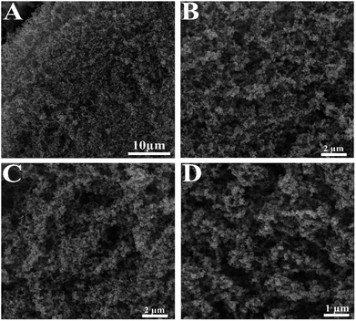 | ||
| Fig. 2 The FESEM images at different magnifications show porous 3D network with large open pores of the Pd–Cu aerogel. | ||
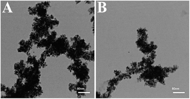 | ||
| Fig. 3 TEM images of the Pd–Cu aerogel at various magnifications. The TEM images display the coalescence of the Pd nanoparticles into chainlike network structures. | ||
As shown, the Pd–Cu aerogel demonstrates a 3D network with high porosity and extended nanochains. Besides, these images obviously represent profuse open pores and tunnels.
The TEM images of the Pd–Cu aerogel at various magnifications are shown in Fig. 3. Obviously, these images display the coalescence of the initial spherical NPs into chainlike nanostructures. Moreover, the TEM images illustrate the extended nanochains interconnected network of the as-prepared Pd–Cu aerogel.
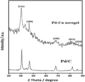
The XRD was utilized for the assessment of crystalline phase of Pd–Cu aerogel. Fig. 4 displays the XRD pattern of the Pd–Cu aerogel. The XRD pattern of the Pd/C catalyst is presented in Fig. 4. The diffraction peaks are related to the face centered cubic (FCC) crystal structure of Pd (JCPDS # 46-1043) with lattice parameter value of 0.3907 nm.
As shown, for Cu, the diffraction peaks are located at 2 theta values of 43.3°, 50.4°, 74.1° and 89.9° (JCPDS # 85-1326). In addition, for Pd, the strong diffraction peaks are placed at 2 theta values of 40.2°, 46.7°, 68.3°, 82.3° and 86.8°, which are associated with the (111), (231), (321) and (222) reflection (JCPDS # 87-0639), respectively. These reflection peaks corroborate face centred cubic (FCC) crystal structures for Pd and Cu elements.
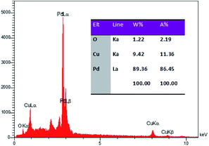
The Rietveld analysis showed a slightly smaller Pd lattice parameter (0.3881 nm) in the Pd–Cu aerogel that suggests that Pd and Cu are alloyed in the Pd–Cu aerogel, because alloying Pd with Cu would decrease the lattice parameter due to the smaller size of Cu atoms. To evaluate the chemical compositions of the Pd–Cu aerogel, the EDS analysis was applied. Fig. 5 presents the EDS spectrum of the Pd–Cu aerogel, and the results are summarized in Table inset of Fig. 5. It can be observed that the EDS spectrum demonstrates the presence of Pd and Cu elements in the Pd–Cu aerogel sample with mass percentages equal to 89.36 and 9.42 wt%, respectively. To study the chemical composition of the as-synthesized Pd–Cu aerogel the ICP-AES analysis was carried out. The ICP-AES analysis confirms presence of Pd and Cu with the mass percentage 87.3 and 12.7%, respectively. The TEM, FESEM, XRD, and ICP-AES analyses well confirm the creation of Pd–Cu aerogel with a large porosity and profuse open pores during the synthesis process shown in Fig. 1.
Electrocatalytic performances
Fig. 6(A) compares the electrochemical activities of resultant aerogel with th Pd/C utilizing CVs recorded in 0.5 M H2SO4 solution. As represented, the designated areas in each CV profile are related to the desorption of hydrogen (I), formation of PdO (II), reduction of PdO (III), and adsorption of hydrogen (IV) areas. Clearly, the ad/desorption of hydrogen, production and reduction of PdO peaks on the Pd/C surface are lower than that of Pd–Cu aerogel, which confirms the greater surface area of Pd–Cu aerogel. It is proved that the electrochemical active surface area (ECSA) of a catalyst is a suitable index to assess the performance of a catalyst. Hence, CV was utilized as a powerful technique for the calculation of ECSA of a sample, which not only offers very good information concerning the number of electrochemically active sites of catalyst, but is also an excellent index to compare different electrocatalytic supports. The integrated area under the desorption peak in the cyclic voltammograms shows the total charge relating to H+ desorption, QH, and can be utilized to determine ECSA of a catalyst according to the following eqn (1):22| ECSA = QH/0.21 × Pdm | (1) |
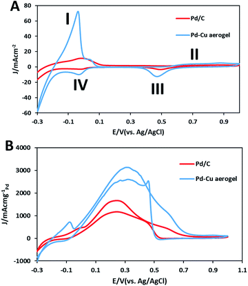 | ||
| Fig. 6 (A) Cyclic voltammograms of the Pd–Cu aerogel and Pd/C catalysts in 0.5 M H2SO4 solution, and (B) 0.5 M H2SO4, 0.5 M HCOOH solution at sweep rate of 50 mV s−1. | ||
We investigated the electrocatalytic activities of the as-synthesized Pd–Cu aerogel and Pd/C samples toward FAO in 0.5 M H2SO4 solution. Fig. 6B compares the catalytic activities of both samples for the oxidation of HCOOH by using the CVs recorded in the solution 0.5 M H2SO4 + 0.5 M formic acid. It has been established that the oxidation of formic acid on Pt and Pd-based catalysts surface was carried out according to the two mechanisms as follows:23
| HCOOH → CO2 + 2H+ + 2e− | (2) |
| HCOOH → COads + H2O | (3) |
| COads + H2O → CO2 + 2H+ + 2e− | (4) |
Selective direct pathway (dehydrogenation pathway, eqn (2)) is indispensable for the creation of H2 without undesirable dehydration since carbon monoxide (CO) created by the dehydration pathway (eqn (3) and (4)) significantly reduces the activity of catalysts. Indirect pathway goes along with the production of COads intermediate species (eqn (3)), which are strongly bonded on the catalyst surface, and lead to the catalyst deactivation.
It is generally agreed that the electrooxidation reaction of formic acid proceeds on Pd metal surface primarily through the direct pathway (dehydrogenation pathway) without CO poisoning.23 In each CV profile, during the forward sweeps, the main oxidation peaks for Pd–Cu aerogel and Pd/C appeared in the potentials of 0.31 and 0.244 V, respectively, which are related to the FAO on Pd surfaces. Nonetheless, minor humps at around 0.55 to 0.7 V for Pd–Cu aerogel and 0.45 to 0.65 V for Pd/C are observed, which can be related to the oxidation reaction of the Pd surfaces. Both samples in the reverse sweeps show two specified peaks; the peaks at around 0.5 to 0.42 V are associated with the reduction of PdO, and the resultant peaks at the potentials of 0.332 V and 0.243 V on Pd–Cu aerogel and Pd/C, respectively, are attributed to the FAO on the newly reduced Pd surfaces. Obviously, the Pd–Cu aerogel represents extraordinary current density toward FAO (3130.1 mA mgPd−1), which is superior in comparison to the Pd/C (1670.9 mA mgPd−1). Moreover, the Pd–Cu aerogel illustrated a negative shift in the onset oxidation potential (−0.024 vs. 0.037 V) than that of Pd/C. The 61 mV negative shift of the onset oxidation potential for Pd–Cu aerogel compared to the Pd/C demonstrates an improvement in the kinetics of the electrooxidation of formic acid on the Pd–Cu aerogel surface.24–26 The considerable electrocatalytic activity of the Pd–Cu aerogel is due to the high surface area which allows effective mass transport through the large open pores and easier access to active sites.
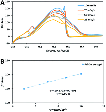
To evaluate the mass transport in FAO on electrode decorated with the Pd–Cu aerogel, CV tests were taken at various sweep rates in the mixture of a solution 0.5 M H2SO4 and 0.5 M HCOOH at RT (Fig. 7A). The obtained results for Pd–Cu aerogel demonstrated that the oxidation peaks of FAO were clearly promoted with the increase in sweep rate. Moreover, Fig. 7B displays a linear relationship between the oxidation peaks and ν1/2 (square root of scan rates), confirming that the FAO may be controlled by a mass transport.27–29
The long-term stability of the as-synthesized Pd–Cu aerogel and Pd/C were also evaluated by using the chronoamperometry (CA) tests in the solution 0.5 M H2SO4 containing 0.5 M formic acid at a constant potential of 0.3 V (vs. Ag/AgCl) for 7200 s at RT (shown in Fig. 8).
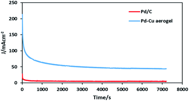 | ||
| Fig. 8 Chronoamperometry curves of the Pd–Cu aerogel and Pd/C at potential of 0.3 V (vs. Ag/AgCl) for 7200 s. | ||
Obviously, in each curve of CA related to the Pd–Cu aerogel and Pd/C samples, at the early stage of CA tests, the Pd–Cu aerogel and Pd/C showed a high current owing to the double layer charging process as well as abundant active sites on the surfaces of both catalysts. Because of the production of some intermediate carbonaceous species during the electrooxidation reaction of formic acid, Pd–Cu aerogel and Pd/C catalysts depict a quick decay at current densities of CA before a steady current status is attained. The intense decay in current density because of the production and adsorption of intermediate carbonaceous species on the catalysts surface goes along with the block of active sites as well as poisoning of catalysts surface.30–40 After an early intense drop in performance, the current densities were stabilized at 5.2 and 45.6 mA cm−2 for Pd/C and Pd–Cu aerogel, respectively. The very high catalytic activity and durability of the Pd–Cu aerogel than that of Pd/C are attributed to the two vital reasons: (1) the presence of abundant open pores as well as easy access to large active sites of Pd–Cu aerogel, and (2) the self-supporting property of the Pd–Cu aerogel, which may hinder the loss of stability observed in Pd supported on carbon owing to corrosion.
To evaluate the electrochemical behaviors of both catalysts, electrochemical impedance spectroscopy (EIS) measurements were performed. The Nyquist plots related to the Pd–Cu aerogel and Pd/C are shown in Fig. 9. The values of charge transfer resistance (RCT) for Pd–Cu aerogel and Pd/C were found to be 100 and 354 Ω, respectively. The standard exchange current density (i0) is used for the assessment of the catalytic activity of a sample. The values of i0 for both catalysts were estimated from RCT according to the following eqn (5):23,27
| i0 = RT/nFRCT | (5) |
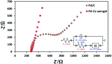 | ||
| Fig. 9 The Nyquist plots recorded at potential of 0 V for the Pd–Cu aerogel and Pd/C in the solution of 5 mM [Fe(CN)6]3−/4− prepared in 0.1 M KCl (F). | ||
Conclusions
In summary, we report a simple and efficient strategy to prepare the Pd–Cu aerogel. This way offers a number of advantages including one-pot synthesis, simplicity, and short time to prepare the hydrogel. The Pd–Cu aerogel was prepared in the presence of sodium carbonate utilizing glyoxylic acid monohydrate as a reductant agent followed by supercritical CO2 drying. The TEM, FESEM, XRD, and ICP-AES analyses well confirm the creation of porous 3D network with numerous open pores of Pd–Cu aerogel during the controlled coalescence of Pd and Cu NPs in aqueous media. The Pd–Cu aerogel was applied as an anode unsupported catalyst toward FAO, and illustrated much higher electrocatalytic performance and durability compared to the Pd/C. The extraordinary activity and stability of Pd–Cu aerogel are ascribed to the high surface area, which allows effective mass transport through the pores, and easier access to active sites. Moreover, the self-supporting property of the Pd–Cu aerogel may hinder the loss of stability observed in Pd catalyst supported on carbon owing to corrosion. We believe that the resultant aerogel via this approach is an efficient and promising catalyst for direct formic acid fuel cells (DFAFCs) and widespread applications such as photonic, catalysis, sensors, etc.Conflicts of interest
There are no conflicts to declare.References
- Y. Zhou, C. Du, G. Han, Y. Gao and G. Yin, Electrochim. Acta, 2016, 217, 203–209 CrossRef.
- Y. Wang, Q. He, H. Wei, J. Guo, K. Ding, Q. Wang, Z. Wang, S. Wei and Z. Guo, Electrochim. Acta, 2015, 184, 452–465 CrossRef PubMed.
- F. Yang, Y. Zhang, P.-F. Liu, Y. Cui, X.-R. Ge and Q.-S. Jing, Int. J. Hydrogen Energy, 2016, 41, 6773–6780 CrossRef.
- Q. Zhao, J. Wang, X. Huang, Y. Yao, W. Zhang and L. Shao, Electrochem. Commun., 2016, 69, 55–58 CrossRef.
- R. Krishna, D. M. Fernandes, A. Marinoiu, J. Ventura, C. Freire and E. Titus, Int. J. Hydrogen Energy, 2017, 42, 23639–23646 CrossRef.
- D. Chen, P. Cui, H. He, H. Liu and J. Yang, J. Power Sources, 2014, 272, 152–159 CrossRef.
- S. Hu, L. Scudiero and S. Ha, Electrochim. Acta, 2012, 83, 354–358 CrossRef.
- Y. Lu and W. Chen, ACS Catal., 2011, 2, 84–90 CrossRef.
- Y. Lu and W. Chen, J. Phys. Chem. C, 2010, 114, 21190–21200 CrossRef.
- D.-N. Li, A.-J. Wang, J. Wei, Q.-L. Zhang and J.-J. Feng, Int. J. Hydrogen Energy, 2017, 42, 19894–19902 CrossRef.
- Y. Wang, Z. Xiong and Y. Xia, RSC Adv., 2017, 7, 40462–40469 RSC.
- L. La, X. Zhang, A. Ma, Y. Zhang, H. Huang and S. Lin, RSC Adv., 2016, 6, 107370–107378 RSC.
- H. Rasouli, S. H. Tabaian and M. Rezaei, RSC Adv., 2016, 6, 22500–22510 RSC.
- K. Miao, Y. Luo, J. Zou, J. Yang, F. Zhang, L. Huang, J. Huang, X. Kang and Sh. Chen, Electrochim. Acta, 2017, 251, 588–594 CrossRef.
- J. N. Zheng, M. Zhang, F. F. Li, S. S. Li, A. J. Wanga and J. J. Feng, Electrochim. Acta, 2014, 130, 446–452 CrossRef.
- C. Zhu, D. Du, A. Eychmüller and Y. Lin, Chem. Rev., 2015, 115, 8896–8943 CrossRef PubMed.
- D. Wen and A. Eychmüller, Chem. Commun., 2017, 53, 12608–12621 RSC.
- C. Zhu, Q. Shi, S. Fu, J. Song, H. Xia, D. Du and Y. Lin, Adv. Mater., 2016, 28, 8779–8783 CrossRef PubMed.
- A. S. Douk, H. Saravani and M. Noroozifar, Electrochim. Acta, 2018, 275, 182–191 CrossRef.
- B. Cai, D. Wen, W. Liu, A. K. Herrmann, A. Benad and A. Eychmüller, Angew. Chem., Int. Ed., 2015, 54, 13101–13105 CrossRef PubMed.
- S. S. Kistler, Nature, 1931, 127, 741 CrossRef.
- X. Hu, Y. Zhou, H. Wen and H. Zhong, J. Electrochem. Soc., 2014, 161, F583–F587 CrossRef.
- A. S. Douk, H. Saravani and M. Noroozifar, J. Alloys Compd., 2018, 739, 882–891 CrossRef.
- R. Jana, U. Subbarao and S. C. Peter, J. Power Sources, 2016, 301, 160–169 CrossRef.
- A. M. Mohammad, I. M. Al-Akraa and M. S. El-Deab, Int. J. Hydrogen Energy, 2018, 43, 139–149 CrossRef.
- D. Liu, Q. Guo, H. Hou, O. Niwa and T. You, ACS Catal., 2014, 4, 1825–1829 CrossRef.
- A. S. Douk, H. Saravani and M. Noroozifar, Int. J. Hydrogen Energy, 2017, 42, 15149–15159 CrossRef.
- M. Z. Yazdan-Abad, M. Noroozifar, A. R. Modarresi-Alam and H. Saravani, J. Mater. Chem. A, 2017, 5, 13228 RSC.
- A. S. Douk, H. Saravani and M. Noroozifar, Int. J. Hydrogen Energy, 2018, 43, 7946–7955 CrossRef.
- F. Zhu, M. Wang, Y. He, G. Ma, Z. Zhang and X. Wang, Electrochim. Acta, 2014, 148, 291–301 CrossRef.
- C. Venkateswara Rao, C. R. Cabrera and Y. Ishikawa, J. Phys. Chem. C, 2011, 115, 21963–21970 CrossRef.
- C. Du, M. Chen, W. Wang and G. Yin, ACS Appl. Mater. Interfaces, 2010, 3, 105–109 CrossRef PubMed.
- R.-X. Wang, Y.-J. Fan, Z.-R. Liang, J.-M. Zhang, Z.-Y. Zhou and S.-G. Sun, RSC Adv., 2016, 6, 60400–60406 RSC.
- N. He, C. Qin, R. Wang, S. Ma, Y. Wang and T. Qi, RSC Adv., 2016, 6, 68989–68996 RSC.
- S. Jiang, B. Yi, Q. Zhao, H. Yu and Z. Shao, RSC Adv., 2017, 7, 11719–11723 RSC.
- T. Maiyalagan, X. Wang and A. Manthiram, RSC Adv., 2014, 4, 4028–4033 RSC.
- A. Ma, X. Zhang, X. Wang, L. Le and S. Lin, RSC Adv., 2015, 5, 64534–64537 RSC.
- L. Le, X. Zhang, A. Ma, Y. Zhang, H. Huang and S. Lin, RSC Adv., 2016, 6, 107370–107378 RSC.
- Zh. Wang, Ch. Lu, W. Kong, Y. Zhang and J. Li, J. Alloys Compd., 2017, 690, 95–100 CrossRef.
- M. Kübler, T. Jurzinsky, D. Ziegenbalg and C. Cremers, J. Power Sources, 2018, 375, 320–334 CrossRef.
| This journal is © The Royal Society of Chemistry 2018 |

