 Open Access Article
A separation-free 3D network ZnO/rGO–rGH hydrogel: adsorption enriched photocatalysis for environmental applications†
Chong Liu‡
,
Mengting Yue‡,
Li Liu,
Yulan Rui and
Wenquan Cui *
*
College of Chemical Engineering, Hebei Key Laboratory for Environment Photocatalytic and Electrocatalytic Materials, North China University of Science and Technology, Tangshan 063210, P. R. China. E-mail: wqcui@ncst.edu.cn
First published on 19th June 2018
Abstract
This study describes the encapsulation of ZnO by reduced graphene oxide to form a composite (ZnO/rGO) that can be incorporated into graphene to form hydrogels (ZnO/rGO–rGH) with three-dimensional (3D) network structures. The unique surface adsorption characteristics of graphene make ZnO/rGO–rGH materials have the ability of fast adsorption and desorption. Meanwhile, the combination of graphene and ZnO nanoparticles can promote the separation efficiency of electrons and holes and improve the photocatalytic activity. The sample showed the highest adsorption-photocatalysis synergistic activity and removed 100% of the BPA (10 mg L−1) within 20 min under UV irradiation. The purification efficiency of ZnO/rGO–rGH can reach more than 90% after 5 rounds of repeated use. We also measured the performance of ZnO/rGO–rGH in removing BPA under flow conditions, and the results showed that this approach with ZnO/rGO–rGH removed 100% of the BPA in 16 h.
Introduction
Water pollution is an urgent problem. Low concentrations of organic pollutants, such as phenol and bisphenol A (BPA), pose a serious threat to human health and the environment. Unfortunately, they are environmentally persistent, bioaccumulative, highly toxic and difficult to degrade.1–3 Photocatalytic oxidation degradation offers deep oxidation that can thoroughly mineralize the highly toxic and biodegradable organic contaminants.4–6 Photocatalytic oxidation technology is one of the most promising water treatment technologies because of its strong mineralization ability, low energy consumption, and mild reaction conditions.7,8 However, photocatalytic technology is difficult to use due to its low flux and low mineralization rate. Also, the powder catalysts are difficult to recover from water, which limits their practical applications.9,10 Thus, the photocatalytic method is limited, and new methods that utilize photocatalytic materials to remove organic matter are needed.Graphene as a lamellar high specific surface area11,12 carbon material has very high adsorption capacity. The unique surface adsorption characteristics13 of graphene make the adsorption faster and the adsorption intensity higher. Graphene has good electron conductivity, and the surface hybridization between graphene and photocatalytic material can promote the rapid transfer and separation of the photogenerated charge.14,15 This increases the photocatalytic activity via the π–π conjugation of graphene. Graphene hydrogels prepared from graphene oxide not only retain the surface adsorption properties of graphene but also have a unique three-dimensional network structure16–21 and mechanical strength. This avoids the challenges of separating the graphene adsorbent in water.22,23 Further, the composite hydrogel has adsorptive pre-concentration and catalytic degradation properties due to gelation between the oxidized graphene and the photocatalytic materials. The structure of the network hydrogel maintains the layered structure of graphene and still offers rapid adsorptive pre-concentration, easy separation, and good recovery.
Hydrogels have an important role in adsorption separation. The three-dimensional network structure formed by cross-linking polymerization of hydrogels offers a fast adsorption rate and high adsorption capacity.24–27 Zhu et al.28,29 combined TiO2 with polyaniline hydrogel to prepare a TiO2@polyaniline composite hydrogel for synergistic adsorption-photocatalytic treatment of organic matter in water. Zhang et al.30,31 prepared a C3N4–agar hydrogel for the degradation of phenol in water-the degradation efficiency of C3N4 increased 1.3 times. Li et al.32 prepared a titania–graphene composite hydrogel (TiO2–rGH) with high adsorption-photocatalytic synergistic ability. It removed 100% Cr(VI) at low concentrations (5 mg L−1).
It is well known that photocatalysts and the graphene hybrid can promote rapid charge conduction, separate the photogenerated charge, and improve the photocatalytic activity. Here, we combined the adsorption with the efficient charge transfer of graphene and proposed synergistic effects with highly efficient adsorption and rapid photocatalytic degradation in situ via a graphene surface hybrid zinc oxide hydrogel (ZnO/rGO–rGH). The surface adsorption of graphene can quickly adsorb BPA, and the hybridization between graphene and ZnO can promote the rapid transfer and separation of photogenerated charge, while also improving the degradation efficiency of ZnO. In addition, the graphene hybrid zinc oxide hydrogel (ZnO/rGO–rGH) has a macroscopic network structure with good mechanical strength. After water treatment, the composite hydrogel can be directly separated-this solves the difficult problem of removing nanomaterials from treated water.
Experimental
Synthesis of ZnO/rGO–rGH
Graphene oxide (GO) was prepared by Hummers method: add 3.0 g graphite to the three rounds bottomed flask, put the bottom flask in the ice bath, carefully add the 70 mL H2SO4 (98%) and stir the 10 min, so that the graphite powder and the concentrated H2SO4 are mixed evenly. Then add 1.5 g NaNO3 to dissolve in the reaction liquid and take 9 g KMnO4 slowly into the above mixed solution and continue to stir 2.5 h. It should be noted that the water bath temperature must be strictly controlled below 20 °C during the mixing process. Then, the temperature of the reaction system was controlled at 35 °C, the reaction time was 4 h, and then 150 mL deionized water was added into the flask of the round bottom. The temperature of the system rose to 95 °C and continuously stirred 1.5 h. After the end of the reaction, 150 mL deionized water and 20 mL (30%) hydrogen peroxide was added to the flask. This process is the oxidation process of graphite powder, and it can be found that the mixed solution is yellow. Then the reactant was centrifuged with 250 mL of dilute hydrochloric acid (the volume ratio 1![[thin space (1/6-em)]](https://www.rsc.org/images/entities/char_2009.gif) :
:![[thin space (1/6-em)]](https://www.rsc.org/images/entities/char_2009.gif) 10). The precipitate was dialytic (36 mm (MD44) dialytic bag, molecular weight: 8000–14
10). The precipitate was dialytic (36 mm (MD44) dialytic bag, molecular weight: 8000–14![[thin space (1/6-em)]](https://www.rsc.org/images/entities/char_2009.gif) 000) for 7 days, that is, graphene oxide was obtained.
000) for 7 days, that is, graphene oxide was obtained.
The rGH was synthesized according to the literature. Briefly, the GO and VC were mixed at 1![[thin space (1/6-em)]](https://www.rsc.org/images/entities/char_2009.gif) :
:![[thin space (1/6-em)]](https://www.rsc.org/images/entities/char_2009.gif) 10 and then stirred for 30 min. The reagent was heated at 95 °C for 1 h to obtain rGH.
10 and then stirred for 30 min. The reagent was heated at 95 °C for 1 h to obtain rGH.
![[thin space (1/6-em)]](https://www.rsc.org/images/entities/char_2009.gif) :
:![[thin space (1/6-em)]](https://www.rsc.org/images/entities/char_2009.gif) 10, stirring 10 min, heating reaction 60 min in 95 °C water bath, drying 12 h at 80 °C, and finally getting rGO@ZnO.
10, stirring 10 min, heating reaction 60 min in 95 °C water bath, drying 12 h at 80 °C, and finally getting rGO@ZnO.![[thin space (1/6-em)]](https://www.rsc.org/images/entities/char_2009.gif) :
:![[thin space (1/6-em)]](https://www.rsc.org/images/entities/char_2009.gif) 10. The reagent was heated at 95 °C for 1 h to obtain ZnO/rGO–rGH.
10. The reagent was heated at 95 °C for 1 h to obtain ZnO/rGO–rGH.Synthesis of ZnO/AC and ZnO/Al2O3
The ZnO particulate was mixed with AC (activated carbon). The mixture was then transferred to the 50 mL agate ball with a ball mill tank. The ZnO and AC mixture was then subjected to 2 h of grinding at 300 rpm to obtain the ZnO/AC. The synthesis process of ZnO/Al2O3 is the same as that of ZnO/AC.Characterization
Using a Rigaku D/MAX2500 PC (XRD) was used for phase analysis. The working voltage was 40 kV, the working current was 100 mA, and the scanning range was 5 to 80°; the Hitachi S-4800 type field emission scanning electron microscopy (SEM) micro morphology analysis; The morphology and size of the samples were analyzed by Hitachi HT-7700 transmission electron microscope (TEM). The electron beam acceleration voltage was 100 kV; the structure of the samples was analyzed by the Thermo Nicolet Avatar 370 spectrometer Fu Liye transform infrared spectrometer (FTIR), and the KBr compression method was used. The range of the scanning wave number was 4000 to 400 cm−1; the chemical state of samples was determined by X-ray photoelectron spectroscopy (XPS) (British KRATOS XSAM800); the UV visible diffuse reflectance spectroscopy (UV-VIS DRS) is used to test the ultraviolet visible diffuse reflectance spectroscopy (UV-VIS DRS) by the Shimadzu Corporation model of the Shimadzu Corporation. The test wavelength is 200–800 nm, and the standard BaSO4 is a reference substance.Adsorption ability synergy of adsorption and photocatalysis in BPA degradation
Photocatalytic degradation of BPA. The photocatalytic degradation of material was studied with the vertical radiation method. A 250 W mercury lamp (model: XC-ZD400G, main wavelength: 356 nm) was located 10 cm from the reactor. The glass reactor was placed in a circulating water bath to control the temperature to 25 ± 2 °C. Then, 25 mg catalyst powder was added into different initial concentrations of BPA. The catalyst reached adsorption equilibrium in the dark. During the photocatalytic process, a 3 mL aliquot of the reaction suspension was removed periodically and filtered (0.45 μm) to determine the BPA concentration.
The adsorption-photocatalysis synergistic removal of BPA is similar to that of photocatalysis degradation studied by vertical radiation method. There was no dark reaction during the experiment. During evaluation of the cycling performance, three 25 mg samples of ZnO/rGO–rGH were added to the BPA solution (100 mL, 10 ppm) and subjected to adsorption, adsorption/photocatalysis, and adsorption/photocatalysis synergy tests. After each cycle, the catalyst was isolated after 178 μm filtration without any other treatment. This was subsequently added to a fresh BPA solution of the same volume and concentration.
Results and discussion
The 3D-network gel structure of the ZnO/rGO graphene hydrogel
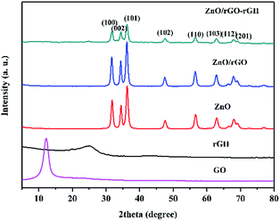
X-ray diffraction (XRD) measurements studied the crystal structure of the materials. Fig. 1 shows typical XRD patterns of the GO, rGH, ZnO, ZnO/rGO and ZnO/rGO–rGH composite. GO oxidation resulted in a 001 diffraction peak that appeared at 12.1°. The typical loose-layer-like structure of GO corresponded to an interlayer spacing of 0.76 nm, which may be due to strong oxidant O and C atoms in the graphite as well as in the upper and lower edges of the graphite sheet positions. Rich oxygen functional groups were introduced on graphene oxide lamellae, which increased the spacing between graphite sheets. In the rGH curve, it can be seen that the GO characteristic peaks disappear and a new wide characteristic peak appears at 24.5°. After adding VC, a part of the oxygen group on the surface of the GO is removed, and the interlayer spacing will be reduced to 0.36 nm, which is in accordance with the XRD of graphene. And the 002 diffraction peak of graphene is broadened, indicating that the larger graphene form of the original is transformed into a smaller size graphene sheet.33The XRD spectra of ZnO, ZnO/rGO and ZnO/rGO–rGH shows that they only contain a dominant ZnO, which is hexagonal wurtzite. This forms a dominant hexagonal wurtzite structure marked by characteristic peaks at 31.9°, 34.3°, 36.2°, 47.6°, 56.6°, 62.8°, 67.8° and 69.2°(JCPDS#36-1451). The corresponding crystal faces of the characteristic peaks are (1 0 0), (0 0 2), (1 0 1), (1 0 2), (1 1 0), (1 0 3), (1 1 2) and (2 0 1).34
No typical diffraction peaks of rGO species are observed in the ZnO/rGO and ZnO/rGO–rGH composite, which may be because rGO is sufficiently dispersed in the composite material surface. Thus, a thin coating layer is not easy to detect, and ZnO nanoparticles were modified in the graphene sheet.35 This effectively inhibited the accumulation of graphene sheets and further expanded graphene layer spacing. The presence of rGO and the relationship of ZnO/rGO composite were confirmed by Raman and FT-IR analyses as described below.
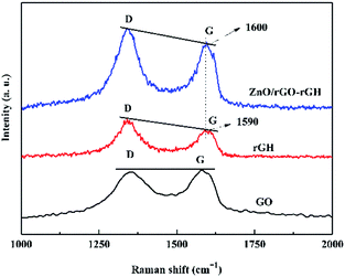
Fig. 2 shows the Raman spectrum of GO, rGH and ZnO/rGO–rGH. There are two sharp and strong characteristic peaks at GO and rGH at 1340 cm−1 and 1590 cm−1, which correspond to D peak and G peak respectively. The D peak represents the edge defect and its amorphous structure of graphene, mainly due to the structural defects caused by the introduction of some oxygen functional groups such as hydroxyl and carboxyl groups. The G peak represents the ordered structure of sp2, and ID![[thin space (1/6-em)]](https://www.rsc.org/images/entities/char_2009.gif) :
:![[thin space (1/6-em)]](https://www.rsc.org/images/entities/char_2009.gif) IG ratio is usually used to measure the defect density and quality of grapheme.36 It can be seen that the ID
IG ratio is usually used to measure the defect density and quality of grapheme.36 It can be seen that the ID![[thin space (1/6-em)]](https://www.rsc.org/images/entities/char_2009.gif) :
:![[thin space (1/6-em)]](https://www.rsc.org/images/entities/char_2009.gif) IG value of rGH by chemical reduction self-assembly is obviously larger than that of GO, indicating that there are some defects in the prepared rGH, and some oxygen functional groups have not been reduction.
IG value of rGH by chemical reduction self-assembly is obviously larger than that of GO, indicating that there are some defects in the prepared rGH, and some oxygen functional groups have not been reduction.
The Raman intensities of ZnO are not seen on the Raman spectrum of ZnO/rGO–rGH, which indicates that the Raman peak intensity of ZnO is weak. Versus the intensity ratio of GO, the intensity ratio (ID![[thin space (1/6-em)]](https://www.rsc.org/images/entities/char_2009.gif) :
:![[thin space (1/6-em)]](https://www.rsc.org/images/entities/char_2009.gif) IG) of ZnO/rGO–rGH increased indicating that a large amount of graphene oxide is reduced during the preparation process. The intensity ratio (ID
IG) of ZnO/rGO–rGH increased indicating that a large amount of graphene oxide is reduced during the preparation process. The intensity ratio (ID![[thin space (1/6-em)]](https://www.rsc.org/images/entities/char_2009.gif) :
:![[thin space (1/6-em)]](https://www.rsc.org/images/entities/char_2009.gif) IG) of ZnO/rGO–rGH is further increased, and this might cause the ZnO nanospheres to be attached to the graphene sheets. This results from introduction of defects. Of note, the slight shift in the D and G peaks in the Raman spectra of ZnO/rGO–rGH could indicate that the interaction of rGO and ZnO generates surface hybridization after the interaction process.37
IG) of ZnO/rGO–rGH is further increased, and this might cause the ZnO nanospheres to be attached to the graphene sheets. This results from introduction of defects. Of note, the slight shift in the D and G peaks in the Raman spectra of ZnO/rGO–rGH could indicate that the interaction of rGO and ZnO generates surface hybridization after the interaction process.37
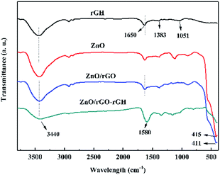
The FT-IR of rGH, ZnO, ZnO/rGO, and ZnO/rGO–rGH are shown in Fig. 3. For the GO, there are two characteristic absorption peaks in the 1000–1800 cm−1 interval, at 1064 cm−1 and 1391 cm−1, due to the elastic vibration of the C–O and C–OH, respectively. In addition, there are two characteristic absorption peaks at 1635 cm−1 and 1735 cm−1, mainly due to the bending vibration of the hydroxyl group and the elastic vibration of the carbonyl group (C![[double bond, length as m-dash]](https://www.rsc.org/images/entities/char_e001.gif) O).38 When GO is reduction to rGH, the absorption summit corresponding to C
O).38 When GO is reduction to rGH, the absorption summit corresponding to C![[double bond, length as m-dash]](https://www.rsc.org/images/entities/char_e001.gif) O is obviously weakened, even the corresponding peak of C–OH vanishes. When ZnO and rGO are hybridized, it is possible to see that the characteristic absorption peaks of ZnO in ZnO/rGO widen compared to ZnO, and a slight red shift occurs, which may be caused by the interaction of the interaction of rGH and ZnO.
O is obviously weakened, even the corresponding peak of C–OH vanishes. When ZnO and rGO are hybridized, it is possible to see that the characteristic absorption peaks of ZnO in ZnO/rGO widen compared to ZnO, and a slight red shift occurs, which may be caused by the interaction of the interaction of rGH and ZnO.
Subsequently, in order to study the optical properties of the composites at different wavelengths, UV visible diffuse reflectance tests (Fig. S1†) for the samples of rGH, ZnO, rGO@ZnO, and rGH–rGO@ZnO were carried out. Monomeric ZnO only responded to UV light, and the absorption wavelength of ZnO range is below 420 nm. ZnO and a small amount of lamellar graphene compounded to form hybrid material rGO@ZnO. The composite had a weak reflective property to visible light and improved absorption performance. The absorbance of rGH–rGO@ZnO composite hydrogel in visible light area is obviously improved. It is obvious that the introduction of large amount of graphene is conducive to the absorption of visible light by composite. The optical absorption band edge of the rGO@ZnO composite has a slight red shift compared with the monomer ZnO. It shows that the bonding between ZnO and graphene has a certain bonding effect. ZnO and rGO have formed a new valence bond structure through the bond, and the rGO@ZnO hybrid system has been successfully established.
The structure and morphology of the monomer graphene hydrogel were analyzed by field emission scanning electron microscope (Fig. 4). The microstructure of rGH prepared by chemical reduction method is shown in Fig. 4a and b. It can be seen that rGH has rich three-dimensional spatial network structure. The partial overlapping of the graphene nanosheets suggests cross linking in the hydrogel structures. The formation of this unique structure is likely due to hydrophobic interactions during the π–π interaction between the graphene sheets and the intermolecular forces.
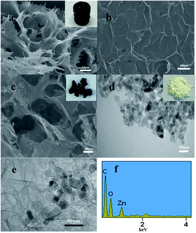 | ||
| Fig. 4 SEM images of (a) and (b) rGH; (c) ZnO/rGO–rGH; and (d) the TEM of ZnO; (e) the TEM of ZnO/rGO–rGH; and (f) the EDS of ZnO/rGO–rGH. | ||
Fig. 4c is the SEM diagram of the ZnO/rGO–rGH composite. It can be seen that the ZnO nanoparticles are dispersed in the three-dimensional channel of the graphene hydrogel, which effectively prevents the accumulation of graphene lamellae. This increases the specific surface area of rGH. The TEM image of ZnO/rGO–rGH further confirmed the lamellar structure of the graphene hydrogel with some chiffon-like ripples and wrinkles. Fig. 4d is the TEM map of ZnO nanoparticles. It can be seen that the diameter of the ZnO nanoparticles is about 20 nm, and the aggregation phenomenon is more obvious. From the TEM diagram of composite material (Fig. 4e), we can see the nanosheet structure of rGH, and the color is obviously deepened in the overlapping area, and nano ZnO is more evenly distributed on graphene layer.
The EDS of ZnO/rGO–rGH indicates that the ZnO/rGO–rGH composite contains rGH and ZnO and is consistent with the XRD results. The functionalized porous 3D structures of ZnO/rGO–rGH with hierarchical structure and unique surface adsorption will reduce the transfer resistance of BPA diffusion, which will provide better channels and adsorption sites for BPA. This results in a high adsorption rate and a large adsorption capacity. Therefore, the synergetic effects of adsorption and surface hybridization facilitate the enhanced BPA purification.
Fig. 5a and b are XPS maps of C 1s elements of GO and rGH–ZnO@rGO, respectively. It can be seen from the diagram that there are four characteristic peaks in the C 1s XPS spectrum of GO: the C![[double bond, length as m-dash]](https://www.rsc.org/images/entities/char_e001.gif) C, C–C&C–H bonds (284.8 eV), the C–OH bonds (hydroxyl) (286.6 eV), the C–O–C&C
C, C–C&C–H bonds (284.8 eV), the C–OH bonds (hydroxyl) (286.6 eV), the C–O–C&C![[double bond, length as m-dash]](https://www.rsc.org/images/entities/char_e001.gif) O bonds (287.9 eV), the HO–C
O bonds (287.9 eV), the HO–C![[double bond, length as m-dash]](https://www.rsc.org/images/entities/char_e001.gif) O bonds (288.8 eV). Compared with the XPS spectra of C 1s of GO, the C
O bonds (288.8 eV). Compared with the XPS spectra of C 1s of GO, the C![[double bond, length as m-dash]](https://www.rsc.org/images/entities/char_e001.gif) C, C–C&C–H (284.8 eV) and C–OH (286.6 eV) diffraction peaks of rGH–ZnO@rGO have weakened. In the process of rGH–ZnO@rGO preparation, the addition of the reductant ascorbic acid, a large number of oxygen containing functional groups were reduced, resulting in the existence of some carbon in the form of sp3 hybrid as sp2 hybrid. And this conjugation is conducive to the conduction of photo-generated charge. In addition, the oxygen-containing functional groups that have not been completely removed make the complexes have good hydrophilic properties and help the purification of the composite hydrogel in water. Fig. 5c and d was XPS maps of Zn 2p elements of ZnO and ZnO@rGO, respectively. In Fig. 5c, two diffraction peaks appear at 1022 eV and 1045.1 eV, corresponding to Zn 2p1/2 and Zn 2p2/3, respectively. For ZnO@rGO, it can be found that the diffraction peaks of Zn 2p1/2 and Zn 2p2/3 appear at the binding energies of 1021.2 eV and 1044.3 eV, respectively, and have a negative shift (−0.8 eV) compared to the monomer ZnO. It indicates that the bonding effect between ZnO and rGO can effectively promote the transfer of photoelectrons and enhance the photocatalytic activity of the catalyst.39
C, C–C&C–H (284.8 eV) and C–OH (286.6 eV) diffraction peaks of rGH–ZnO@rGO have weakened. In the process of rGH–ZnO@rGO preparation, the addition of the reductant ascorbic acid, a large number of oxygen containing functional groups were reduced, resulting in the existence of some carbon in the form of sp3 hybrid as sp2 hybrid. And this conjugation is conducive to the conduction of photo-generated charge. In addition, the oxygen-containing functional groups that have not been completely removed make the complexes have good hydrophilic properties and help the purification of the composite hydrogel in water. Fig. 5c and d was XPS maps of Zn 2p elements of ZnO and ZnO@rGO, respectively. In Fig. 5c, two diffraction peaks appear at 1022 eV and 1045.1 eV, corresponding to Zn 2p1/2 and Zn 2p2/3, respectively. For ZnO@rGO, it can be found that the diffraction peaks of Zn 2p1/2 and Zn 2p2/3 appear at the binding energies of 1021.2 eV and 1044.3 eV, respectively, and have a negative shift (−0.8 eV) compared to the monomer ZnO. It indicates that the bonding effect between ZnO and rGO can effectively promote the transfer of photoelectrons and enhance the photocatalytic activity of the catalyst.39
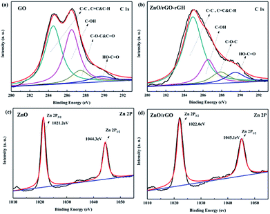 | ||
| Fig. 5 C 1s XPS spectrum of (a) GO, (b) ZnO/rGO–rGH; Zn 2p XPS spectrum of (c) ZnO, and (d) ZnO/rGO. | ||
The synergy of adsorption and photocatalysis in a static system
The BPA adsorption of ZnO/rGO–rGH, ZnO/AC (activated carbon), ZnO/Al2O3, and ZnO was compared (Fig. 6). The adsorption of ZnO/rGO–rGH increased quickly in the beginning of adsorption process and then was mild until equilibrium was reached within 30 min. The saturated sorption capacity of ZnO/rGO–rGH for BPA was about 44.36 mg g−1. However, the adsorption property of ZnO/AC and ZnO/Al2O3 increased relatively slow in the adsorption process, which finally reached equilibrium after 90 min with the low saturated sorption capacity was 18.69 mg g−1, 13.73 mg g−1, respectively. Compared with ZnO/AC and ZnO/Al2O3, the equilibrium adsorption capacities of ZnO/rGO–rGH were 2.37 and 2.23 times higher, respectively. The adsorption property of ZnO/rGO–rGH was superior to the other adsorbing medium showing high adsorption speed and adsorption capacities. This is mainly due to surface adsorption and π–π conjugate adsorption properties of graphene with a higher adsorption capacity. The ZnO nanospheres effectively prevent aggregation of the graphene nanosheets. They increase the surface area of composite material, which will provide better channels and adsorption sites to reduce the transfer resistance of BPA diffusion.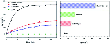 | ||
| Fig. 6 Adsorption capacities of different composite materials during removing BPA (C0 = 10 mg L−1, [catalyst] = 25 mg). | ||
Equivalent composite material was added to 2 ppm, 5 ppm, 10 ppm, 20 ppm, 30 ppm, 40 ppm and 50 ppm BPA for adsorption experiments. The adsorption reaction was 90 min to ensure the adsorption equilibrium, and the composite material was saturated with adsorption. The equilibrium concentration Ce of BPA solution with different concentration is used as the transverse coordinate, and qe is the equilibrium adsorption amount. It is the longitudinal coordinate and is used to obtain the adsorption isotherm.
The adsorption isotherm is a common method to investigate the adsorption properties of composite materials during adsorption. This demonstrate the interaction between ZnO/rGO–rGH composite hydrogel and BPA in more detail and shows the adsorption capacity of ZnO/rGO–rGH composite hydrogel. Fig. S2a† shows the saturated adsorption of the ZnO/rGO–rGH composites during BPA removal under different concentrations. The results prove that the BPA adsorption by ZnO/rGO–rGH follows the Langmuir isotherm model. Concentration is an important factor affecting the adsorption process. The higher concentration can increase the mass transfer force between the adsorbate and adsorbent. This facilitates rapid transfer of BPA to the adsorption site of ZnO/rGO–rGH. The adsorption process of BPA on ZnO/rGO–rGH was also simulated by quasi-first-order kinetics and quasi-second-order kinetics, respectively. The results are shown in Fig. S2b.† The equilibrium adsorption capacity obtained by the experiment conforms to the quasi-second-order kinetic model.
Photocatalytic experiments of ZnO/rGO used degradation of phenol under UV light because there is no absorption to phenol. Fig. 7 shows that graphene loading is 0.5 wt% on the catalyst surface. Here, ZnO/rGO has the highest photocatalytic activity, and it can remove about 98% phenol in 12 min. Versus monomeric ZnO, the degradation efficiency is obviously improved and the surface hybridization effect increased the photodegradation rate of ZnO by 2.5 times. This is mainly because the surface hybrid structure formed by a small amount of graphene and zinc oxide helps to improve the separation of from the photoelectron hole pair, which can double the photocatalytic activity of the single ZnO.
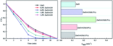 | ||
| Fig. 7 Photocatalytic activity of the ZnO/rGO with different ratios during phenol removal (C0 = 5 mg L−1, [catalyst] = 25 mg). | ||
The photocatalytic activity of each samples was investigated by evaluating the photodegradation of BPA under UV light. The adsorption and photocatalytic activity of ZnO, rGH, ZnO/rGO, and ZnO/rGO–rGH are shown in Fig. 8. The ZnO and ZnO/rGO did not adsorb BPA during the dark reaction. However, the adsorption capacity of rGH and ZnO/rGO–rGH increased quickly in the beginning and then rose slowly until the adsorption equilibrium was reached within 30 min. After adsorption equilibrium, the BPA adsorption removal rate is 65% and 59%, respectively. Photocatalysis played a leading role when the light was irradiated. When ZnO/rGO–rGH was used to degrade BPA for 30 min, the removal rate of BPA in water reached 100%, showing high catalytic activity. Compared with pure rGH, ZnO and ZnO/rGO, ZnO/rGO–rGH has the advantage of unique surface adsorption and large specific surface area of graphene sheets, which can adsorb and enrich BPA rapidly.
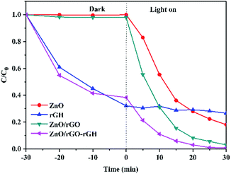 | ||
| Fig. 8 Comparison of photocatalytic activity of the ZnO, rGH, ZnO/rGO and ZnO/rGO–rGH during removing BPA (C0 = 10 mg L−1, [catalyst] = 25 mg). | ||
Fig. S3† illustrates the adsorption-photocatalytic degradation of BPA with the composites of different rGH ratios. Fig. S3a† shows that although the graphene loading was different, all ZnO/rGO–rGH composites have effective adsorption-photocatalytic activity. This shows the efficient purifying effects. The highest adsorption-photocatalytic activity is 20 wt% graphene, i.e., ZnO/rGO–rGH (20%). This material can remove 100% of the BPA in 60 min. When the loading amount was below or exceed 20 wt%, the degradation of ZnO/rGO–rGH composites will be reduced. This is attributed to the different adsorption performance of ZnO/rGO–rGH composites during the dark reaction stages. The loading of rGH increased in ZnO/rGO–rGH (20 wt%) composite, while the relative content of ZnO/rGO decreased. This increased the accumulation of internal graphene layers and reduced the three-dimensional network structure.
The results are shown in Fig. S3b and c† – the adsorption process conforms to a second-order kinetic model, and the photodegradation process is a first-order kinetic model. Fig. S3b† shows the reaction rate of dark reaction process by ZnO/rGO–rGH with different ratios. When the loading of rGH is 20 wt%, 40 wt%, 60 wt%, or 80 wt%, the corresponding rate constants (k) of the composite hydrogels were 2.30 × 10⁻² m3 mol−1 s−1, 1.29 × 10⁻² m3 mol−1 s−1, 9.31 × 10⁻³ m3 mol−1 s−1, 7.67 × 10⁻³ m3 mol−1 s−1, respectively. When the loading of rGH in the composite is 20 wt%, the adsorption property of ZnO/rGO–rGH is the highest.
The results demonstrated the ZnO nanoparticles had a great influence on the adsorption property of the hydrogel composites. The ZnO nanoparticles will act as support points to prevent aggregation of the graphene nanosheets and improve the adsorption capacity. Fig. S3c† shows the reaction rate of the photocatalytic reaction process by ZnO/rGO–rGH with different ratios. The photocatalytic reaction in the process of light reaction accords with the first order kinetic equation. When the loading of rGH is 20 wt%, 40 wt%, 60 wt%, and 80 wt%, the rate constants (k) of composite hydrogel were 8.67 × 10⁻² min−1, 1.08 × 10⁻¹ min−1, 1.28 × 10⁻¹ min−1, 1.45 × 10⁻¹ min−1, respectively. It can be seen that when the proportion of ZnO/rGO in ZnO/rGO–rGH is high, the photocatalytic purification ability of ZnO/rGO–rGH to BPA is lower. This may be due to the excessive amount of ZnO/rGO aggregation. When the ZnO nanoparticles are excited by UV light, the photogenerated electrons do not rapidly transfer to rGH, and this limits their photocatalytic activity.
Fig. S4† illustrates the adsorption-photocatalytic degradation of different BPA concentration with the composites. Fig. S4a† shows data with the ZnO/rGO–rGH composite employed as a composite photocatalyst hydrogel. After the dark reaction is finished, the photocatalytic degradation of BPA phase. The ZnO/rGO–rGH composite can remove 10 mg L−1 of BPA in 30 min to achieve complete purification. The time of degradation for BPA at a concentration of 5 mg L−1 is 15 min. Fig. S4b† shows the reaction rate of the dark reaction process. The adsorption process conforms to a second-order kinetic model. When the initial concentration of BPA is 20 mg L−1, 15 mg L−1, 10 mg L−1 and 5 mg L−1, the corresponding rate constants (k) of the composite hydrogel were 1.47 × 10⁻² m3 mol−1 s−1, 1.97 × 10⁻² m3 mol−1 s−1, 2.30 × 10⁻² m3 mol−1 s−1 and 3.92 × 10⁻² m3 mol−1 s−1, respectively. The adsorption rate decreased as the initial concentration of BPA increased. The adsorption rate of BPA with the initial concentration of 5 mg L−1 is the highest. This may be because most of the adsorption sites were occupied by high concentration of BPA. Fig. S4c† shows the reaction rate of photocatalytic reaction process by ZnO/rGO–rGH. The photocatalytic reaction process was a first-order kinetic model. When the initial concentration of BPA is 20 mg L−1, 15 mg L−1, 10 mg L−1, and 5 mg L−1, the corresponding rate constants (k) of composite hydrogel were 5.18 × 10⁻² min−1, 7.29 × 10⁻² min−1, 8.67 × 10⁻² min−1, 1.60 × 10⁻¹ min−1, respectively. The reaction rate decreased with the increase of the initial concentration of BPA. The results illustrate the photodegradation of BPA with low concentration has a higher photocatalytic activity.
Fig. S5a† shows the adsorption-photocatalytic synergistic purification of ZnO/rGO–rGH with different ratios for removing BPA. Versus the photocatalytic removal of BPA, adsorption-photocatalytic synergistic purification of ZnO/rGO–rGH (20%) composites is fast and efficient. The removal efficiency of BPA is more than 98% by the synergistic effect of adsorption and photocatalysis in 18 min. The adsorption-photocatalysis synergistic purification of ZnO/rGO–rGH in terms of removal BPA with different initial solution concentration (20 mg L−1, 15 mg L−1, 10 mg L−1 and 5 mg L−1) was investigated as shown in Fig. S5b.† The ZnO/rGO–rGH composite is employed as composite photocatalyst hydrogel, and BPA with different concentrations were quickly and efficiently removed after being directly irradiated for 30 min. When the initial concentration of BPA is 5 mg L−1 and 10 mg L−1, the complete purification times were 15 min and 21 min. The 20 mg L−1 BPA was 88% cleared in 21 min.
Fig. 9 shows the reusability of the material. After 5 cycles, the adsorption capacity of ZnO/rGO–rGH has obviously declined, while the removal of BPA can still keep over 90% under the adsorption and photocatalysis synergism and has high activity and stability. More importantly, ZnO/rGO–rGH is in microns, gel structure with three-dimensional network, the use of the filter can be quickly separated from the reaction mixture, without pressure or centrifugation, filtration and separation of complex measures, easy recovery and utilization, improve the reuse ability of catalytic materials. ZnO/rGO–rGH composite has good mechanical properties, high efficiency adsorption and in situ rapid photocatalytic degradation synergistic effect. It can quickly remove BPA from sewage and solve the problem of loss and separation of most adsorbents in practical applications.
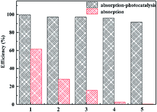 | ||
| Fig. 9 Cycling stability of 20% ZnO/rGO–rGH under different conditions. (C0 = 10 mg L−1, [catalyst] = 25 mg). | ||
The synergy of adsorption and photocatalysis in a continuous flow system
Fig. 10 compares the degradation ability of BPA by adsorption and adsorption-photocatalytic synergism under flow condition. In the dark, the dynamic removal rate of BPA by adsorption was maintained at 100% within 4 h. It then decreased until the adsorption capacity reached saturation. Finally, the adsorption of BPA reached a saturation point at 22 h and lost its adsorption capacity to purify BPA. In direct light conditions, the dynamic adsorption-photocatalytic synergistic of ZnO/rGO–rGH is efficient. The dynamic removal rate of BPA by adsorption-photocatalytic synergies maintained at 100% for 16 h. The removal rate was more than 85% until the purification of adsorption-photocatalytic synergistic reaches equilibrium. The adsorption-photocatalytic synergistic of ZnO/rGO–rGH can achieve the long-term continuous purification of BPA under flow.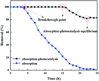 | ||
| Fig. 10 Effect of different flow conditions on BPA removed by ZnO/rGO–rGH (C0 = 10 mg L−1, [catalyst] = 250 mg, u = 0.48 mL min−1). | ||
The adsorption-photocatalysis synergistic purification of BPA with different initial concentrations under UV irradiation is illustrated in Fig. S6a.† When the initial concentration of BPA is 10 mg L−1, 15 mg L−1, and 20 mg L−1, the corresponding breakthrough point are 16 h, 12 h, and 5 h, respectively. The initial concentration of BPA has a large influence on the ZnO/rGO–rGH removal property. The high initial concentration of BPA provides a large driving force for the mass-transfer process and increases the diffusion coefficient.
The adsorption-photocatalysis synergistic effects for the removal of BPA by ZnO/rGO–rGH with different BPA flow rate was investigated (Fig. S6b†). When the flow rate of BPA is 0.48 mL min−1, 0.96 mL min−1, and 1.44 mL min−1, the corresponding breakthrough point are 16 h, 10 h, and 3 h, respectively. Therefore, the initial concentration and flow rate of BPA have a great influence on the degradation activity of ZnO/rGO–rGH. When the initial concentration of BPA is low, slow velocity of flow, the penetration time of the breakthrough point for 16 h, this is because the solution of low concentration, slow velocity of flow, the mass transfer zone moves slower, can maintain a long time continuous removal of BPA, while high concentration solution, high velocity, quickly reach the photocatalytic the equilibrium adsorption, the breakthrough point is shortened to 5 h and 3 h, respectively.
The sustainability of the ZnO/rGO–rGH for removal of BPA under the adsorption-photocatalysis synergistic effect was also investigated (Fig. 11) after the equilibrium of adsorption-photocatalytic efficiency. Then, we immediately turned off the UV light and found that the BPA removal over ZnO/rGO–rGH disappears, and the removal rate is approximately zero. This quickly returns when the light is turned on again. The removal rate (85%) was stable for more than 13 hours demonstrating that the adsorption-photocatalysis synergistic degradation of BPA by ZnO/rGO–rGH composite is efficient and stable.
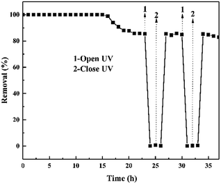 | ||
| Fig. 11 Performance of ZnO/rGO–rGH at alternating dark–light cycles under continuous flow conditions. (C0 = 10 mg L−1, [catalyst] = 250 mg, u = 0.48 mL min−1). | ||
These experiments and analysis suggested a reaction mechanism (Fig. 12). First, the uniform ZnO nanospheres are well dispersed on the 3D graphene sheets. These nanospheres on graphene sheets act as pillars and effectively separate the graphene sheets from each other, which increases the specific surface area of rGH to provide abundant adsorption sites. The graphene material has a unique non-porous surface adsorption, and the ZnO/rGO–rGH material can have a high adsorption rate and large adsorption capacity. Second, the hybridization between 2D graphene sheets and ZnO nanospheres promotes photo-generated charge transport and separation.
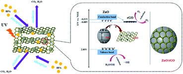 | ||
| Fig. 12 Proposed mechanism for photocatalytic BPA degradation by ZnO/rGO–rGH under ultraviolet-light illumination. | ||
Conclusions
In summary, we synthesized ZnO/rGO–rGH hybrid hydrogel material that has strong adsorption and high photocatalytic activity. The ZnO/rGO–rGH composites solve the problems of low agglomeration, low adsorption capacity, and difficult recovery of powder material. The ZnO/rGO–rGH composites have a good three-dimensional network structure, which shows good adsorption performance for the BPA in water. Compared with ZnO/AC and ZnO/Al2O3, the saturated adsorption capacity of ZnO/rGO-rGH is 2.16 times and 3.34 times, respectively. This fully reflects the strong adsorption performance of graphene hydrogel. At the same time, the ZnO/rGO nanoparticles in the gel system offer rapid in situ degradation of organic pollutants under UV irradiation. The synergistic effects of adsorption and photocatalytic degradation can greatly improve the processing ability of BPA. For 10 ppm BPA, this reached 100% in 20 min. Cycling stability experiments revealed that ZnO/rGO–rGH could achieve a BPA degradation degree of 90% after five repeated cycles. Moreover, under continuous flow conditions, the degree of BPA degradation was maintained at 100% in the first 16 h. In conclusion, ZnO/rGO–rGH hybrid hydrogel material is a promising photocatalyst for the removal and degradation of organic pollutants.Conflicts of interest
The authors declare no competing financial interest.Acknowledgements
This work was financially supported by the National Natural Science Foundation of China (No. 51672081), Key Program of Natural Science of Hebei Province (B2016209375), Hebei Natural Science Funds for the Joint Research of Iron and Steel (B2016209348), The support program for one hundred excellent talents of innovation in Hebei provincial universities (III) (No. SLRC2017049). Chong Liu and Mengting Yue both contributed equally to this work.Notes and references
- A. Sobczyński, Ł. Duczmal and W. Zmudziński, J. Mol. Catal. A: Chem., 2004, 213, 225–230 CrossRef.
- J. Sharma, I. M. Mishra and V. Kumar, J. Environ. Manage., 2015, 156, 266–275 CrossRef PubMed.
- G. C. Behera, N. Biswal and K. Parida, Catal. Today, 2016, 284, 84–91 CrossRef.
- A. Bernabeu, R. F. Vercher, L. Santos-Juanes, P. J. Simón, C. Lardín, M. A. Martínez, J. A. Vicente, R. González, C. Llosá, A. Arques and A. M. Amart, Catal. Today, 2011, 161, 235–240 CrossRef.
- F. Ghanbari, M. Moradi and F. Gohari, J. Water Process Eng., 2016, 9, 22–28 CrossRef.
- J. M. Herrmann, C. Guillard and P. Pichat, Catal. Today, 1993, 17, 7–20 CrossRef.
- M. Muruganandham, R. P. S. Suri, S. Jafari, M. Sillanpää, G.-J. Lee, J. J. Wu and M. Swaminathan, Int. J. Photoenergy, 2014, 2014, 164–167 CrossRef.
- N. Sobana, K. Thirumalai and M. Swaminathan, Can. Chem. Trans., 2016, 4, 77–89 Search PubMed.
- W. C. Wan, S. Yu, F. Dong, Q. Zhang and Y. Zhou, J. Mater. Chem. A, 2016, 4, 7823–7829 RSC.
- Y. E. Moon, G. Jung, J. Yun and H.-I. Kim, Mater. Sci. Eng., B, 2013, 178, 1097–1103 CrossRef.
- J. Xu, L. Wang and Y. Zhu, Langmuir, 2012, 28, 8418–8425 CrossRef PubMed.
- G. C. Yang and P. L. Tang, Water Sci. Technol., 2016, 73, 2268–2274 CrossRef PubMed.
- J. L. Xiao, W. Y. Lv, Z. Xie, Y. Q. Tan, Y. H. Song and Q. Zheng, J. Mater. Chem. A, 2016, 4, 12126–12135 RSC.
- T. G. Xu, L. W. Zhang, H. Y. Cheng and Y. F. Zhu, Appl. Catal., B, 2011, 101, 382–387 CrossRef.
- X. J. Bai, L. Wang, R. L. Zong, Y. H. Lv, Y. Q. Sun and Y. F. Zhu, Langmuir, 2013, 29, 3097–3105 CrossRef PubMed.
- T. Y. Zhao, Z. Y. Liu, K. Nakata, S. Nishimoto, T. Murakami, Y. Zhao, L. Jiang and A. Fujishima, J. Mater. Chem., 2010, 20, 5095–5099 RSC.
- B. Z. Fang, A. Bonakdarpour, K. Reilly, Y. L. Xing, F. Taghipour and D. P. Wilkinson, ACS Appl. Mater. Interfaces, 2014, 6, 15488–15498 CrossRef PubMed.
- B. Z. Fang, Y. L. Xing, A. Bonakdarpour, S. C. Zhang and D. P. Wilkinson, ACS Sustainable Chem. Eng., 2015, 3, 2381–2388 CrossRef.
- S. Q. Fan, B. Z. Fang, J. H. Kim, J. J. Kim, J. S. Yu and J. Ko, Appl. Phys. Lett., 2010, 96, 063501 CrossRef.
- B. Z. Fang, J. H. Kim, M. S. Kim and J. S. Yu, Acc. Chem. Res., 2013, 46, 1397–1406 CrossRef PubMed.
- B. Z. Fang, J. H. Kim, C. Lee and J. S. Yu, J. Phys. Chem. C, 2008, 112, 639–645 CrossRef.
- S. Chen, J. J. Duan, M. Jaroniec and S. Z. Qiao, Angew. Chem., Int. Ed., 2013, 52, 13567–13570 CrossRef PubMed.
- W. J. Liu, J. Y. Cai and Z. H. Li, ACS Sustainable Chem. Eng., 2015, 3, 277–282 CrossRef.
- S. Thakur, S. Pandey and O. A. Arotiba, Carbohydr. Polym., 2016, 153, 34–46 CrossRef PubMed.
- F. N. Muya, C. E. Sunday, P. Baker and E. Lwuoha, Water Sci. Technol., 2016, 73, 983–992 Search PubMed.
- B. Yan, Z. H. Chen, L. Cai, Z. Chen, J. W. Fu and Q. Xu, Appl. Surf. Sci., 2015, 356, 39–47 CrossRef.
- L. Gan, S. M. Shang, E. L. Hu, C. W. M. Yuen and S. X. Jiang, Appl. Surf. Sci., 2015, 357, 866–872 CrossRef.
- W. J. Jiang, Y. F. Liu, J. Wang, M. Zhang, W. J. Luo and Y. F. Zhu, Adv. Mater. Interfaces, 2016, 3 DOI:10.1002/admi.201500502.
- W. J. Jiang, W. J. Luo, R. L. Zong, W. Q. Yao, Z. P. Li and Y. F. Zhu, Small, 2016, 12, 4370–4378 CrossRef PubMed.
- M. Zhang, W. J. Jiang, D. Liu, J. Wang, Y. F. Liu, Y. Y. Zhu and Y. F. Zhua, Appl. Catal., B, 2016, 183, 263–268 CrossRef.
- M. Zhang, W. J. Luo, Z. Wei, W. J. Jiang, D. Liu and Y. F. Zhu, Appl. Catal., B, 2016, 194, 105–110 CrossRef.
- Y. Li, W. Q. Cui, L. Liu, R. L. Zong, W. Q. Yao, Y. H. Liang and Y. F. Zhu, Appl. Catal., B, 2016, 199, 412–423 CrossRef.
- H. Wu, H. W. Chang and J. M. Chern, J. Hazard. Mater., 2006, 137, 336–343 CrossRef PubMed.
- C. Han, Z. Chen, N. Zhang, J. C. Colmenares and Y. Xu, Adv. Funct. Mater., 2015, 25, 221–229 CrossRef.
- N. Takeda, T. Torimoto, S. Sampath, S. Kuwabata and H. Yoneyama, J. Phys. Chem., 1995, 99, 9986–9991 CrossRef.
- J. Du, R. Yu, X. Y. Lai and D. Wang, ACS Nano, 2011, 5, 590–596 CrossRef PubMed.
- S. N. Guo, J. C. Fan, Q. J. Xu and Y. L. Min, RSC Adv., 2015, 5, 64414–64420 RSC.
- K. Wang, H. N. Li, J. Wu, C. Ju, J. J. Yan, Q. Liu and B. Qiu, Analyst, 2011, 136, 3349–3354 RSC.
- H. Moussa, E. Girot, K. Mozet, H. Alem, G. Medjahdi and R. Schneider, Appl. Catal., B, 2016, 185, 11–21 CrossRef.
Footnotes |
| † Electronic supplementary information (ESI) available. See DOI: 10.1039/c8ra03873b |
| ‡ These authors contributed equally to this work. |
| This journal is © The Royal Society of Chemistry 2018 |

