 Open Access Article
A first-principles study on divergent reactions of using a Sr3Fe2O7 cathode in both oxygen ion conducting and proton conducting solid oxide fuel cells†
Wenzhou Tana,
Daoming Huana,
Wenqiang Yanga,
Nai Shia,
Wanhua Wanga,
Ranran Peng *a,
Xiaojun Wu
 a and
Yalin Lu*abcd
aCAS Key Laboratory of Materials for Energy Conversion, Department of Materials Science and Engineering, University of Science and Technology of China, Hefei, 230026 Anhui, China. E-mail: pengrr@ustc.edu.cn; yllu@ustc.edu.cn
bSynergetic Innovation Center of Quantum Information & Quantum Physics, University of Science and Technology of China, Hefei, Anhui 230026, China
cSynchrotron Radiation Laboratory, University of Science and Technology of China, Hefei 230026, P. R. China
dHefei National Laboratory of Physical Science at the Microscale, University of Science and Technology of China, Hefei, 230026 Anhui, China
First published on 25th July 2018
Abstract
Exploring mechanisms for sluggish cathode reactions is of great importance for solid oxide fuel cells (SOFCs), which will benefit the development of suitable cathode materials and then accelerate cathode reaction rates. Moreover, possible reaction mechanisms for one cathode should be different when operating in oxygen ion conducting SOFCs (O-SOFC) and in proton conducting SOFCs (P-SOFCs), and therefore, they lead to different reaction rates. In this work, a Ruddlesden–Popper (R–P) oxide, Sr3Fe2O7 (SFO), was selected as a promising cathode for both O-SOFCs and P-SOFCs. Using the first-principles approach, a microscopic understanding of the O2 reactions over this cathode surface was investigated operating in both cells. Compared with La0.5Sr0.5Co0.25Fe0.75O3 (LSCF), the low formation energies of oxygen vacancies and low migration energy barriers for oxygen ions in SFO make oxygen conduction more preferable which is essential for cathode reactions in O-SOFCs. Nevertheless, a large energy barrier (2.28 eV) is predicted for oxygen dissociation reaction over the SFO (001) surface, while there is a zero barrier over the LSCF (001) surface. This result clearly indicates that SFO shows a weaker activity toward the oxygen reduction, which may be due to the low surface energies and the specific R–P structure. Interestingly, in P-SOFCs, the presence of protons on the SFO (001) surface can largely depress the energy barriers to around 1.46–1.58 eV. Moreover, surface protons benefit the oxygen adsorption and dissociation over the SFO (001) surface. This result together with the extremely low formation energies and migration energy barriers for protons seem to suggest that SFO could work more effectively in P-SOFCs than in O-SOFCs. It's also suggested that too many protons at the SFO surface will lead to high energy barriers for the water formation process, and thus that over-ranging steam concentrations in the testing atmosphere may have a negative effect on cell performances. Our study firstly and clearly presents the different energy barriers for one cathode performing in both O- and P-SOFCs according to their different working mechanisms. The results will be helpful to find the constraints for using cathodes toward oxygen reduction reactions, and to develop effective oxide cathode materials for SOFCs.
Introduction
As green and efficient energy conversion devices, solid oxide fuel cells (SOFCs) have attracted much attention nowadays. According to the conducting ions in their electrolytes, SOFCs can be divided into two categories: oxygen ion conducting SOFCs (O-SOFCs) and proton conducting SOFCs (P-SOFCs). Interestingly, in spite of their conducting ions in electrolytes (protons or oxygen ions), lots of experiments have also suggested that polarization resistances corresponding to the sluggish cathode reactions are one of the main factors to limit the electrochemical performance of SOFCs. As a result, in the past decades, great efforts have been devoted to develop suitable cathode materials to accelerate the cathode reaction rate and to improve the cell performance.1,2As shown in eqn (1) and (2), cathode reactions for O-SOFCs and P-SOFCs are quite different and thus have different requirements on their cathode materials.
| O-SOFC: O2 + 4e− → 2O2− | (1) |
| P-SOFC: 4H+ + O2 + 4e− → 2H2O | (2) |
For O-SOFCs, good oxygen ion and electron conduction are essential to accelerate cathode reactions. To meet such demands, lots of efficient composite cathodes, for example La0.8Sr0.2MnO3−δ–Y0.88Zr0.12O2−δ (LSM–YSZ),3 La0.6Sr0.4Co0.2Fe0.8O3−δ–Sm0.2Ce0.8O1.9 (LSCF–SDC),4 and Ba0.5Sr0.5Co0.8Fe0.2O3−δ–Sm0.2Ce0.8O1.9 (BSCF–SDC),5 have been investigated, where the electrolytes were added to improve oxygen ion conduction or to enlarge length of triple phase boundaries. While for P-SOFCs, proton conduction in addition to electron conduction is urgently needed, and conduction of oxygen ions seems not as vital as in O-SOFCs where oxygen ions need to diffuse to electrolytes and finally to the anode. For P-SOFCs, in addition to those composite cathodes, such as La0.6Sr0.4Co0.2Fe0.8O3−δ–BaZr0.1Ce0.7Y0.2O3−δ (LSCF–BZCY),6 Sm0.5Sr0.5CoO3−δ–BaZr0.1Ce0.7Y0.2O3−δ (SSC–BZCY),7 single phase cathodes, including BaCo0.4Fe0.4Zr0.1Y0.1O3−δ,8 BaCo0.4Fe0.4Zr0.2O3−δ,9 BaCe0.5Fe0.5O3−δ,10 BaZr0.6Co0.4O3−δ,11 and Sr3Fe2O7−δ,12 were also designed and expected to function better than those composites cathodes because of their potential proton–electron mixed conductions which could enlarge the active reaction area to the cathode surface instead of TPB. Proton conduction in these materials are formed via the incorporation of steam molecules into oxygen vacancies, as shown in eqn (3).
 | (3) |
In the past, acceptable performances were achieved with above cathodes. For example, applying BaCo0.4Fe0.4Zr0.2O3−δ, peak power densities of 405 mW cm−2 were achieved at 500 °C for P-SOFCs when using a BaCe0.7Zr0.1Y0.1Yb0.1O3−δ electrolyte.9 Nevertheless, despite of the improved cell performances, in the microscopic view detailed cathode reaction mechanisms and the influences are still frustrating for both O-SOFCs and P-SOFCs. Especially, no discussions with regarding to use one cathode material in both O-SOFCs and P-SOFCs have ever been proposed yet.
It has been generally accepted that the first-principles calculation could provide useful information on revealing and understanding detailed mechanism for catalytic reactions. For instance, Y. Choi et al. have studied oxygen reduction barriers for La0.5Sr0.5MnO3 (LSM0.5) and proposed a fast O2 reduction on LSM0.5 with nonexistence of transition-state barriers.13 Yueh-Lin Lee et al. have demonstrated that the experimentally measured area specific resistance and oxygen surface exchange of solid oxide fuel cell cathode strongly correlate with the theoretical calculation data.14 Sihyuk Choi et al. have studied the possible elementary pathway for the oxygen reduction reaction on PrBa0.5Sr0.5Co2−xFexO5 by DFT analysis, and suggested that the most attractive properties of these materials are the presence of pore channels in the [PrO] and [CoO] planes that provide paths for fast oxygen transport that accelerates the surface oxygen exchange kinetics.1 We have also explored bulk proton transporting and oxygen reduction behaviors on BaZr0.75Co0.25O3 cathodes and found that the BaZr0.75Co0.25O3 a promising cathode for P-SOFCs because of its low proton formation energy, low diffusion energy barrier and its low energy barriers toward cathode reactions at the presence of protons.15 Recently, we found that Sr3Fe2O7 (Ruddlesden–Popper oxides) has low formation energies and diffusion energy barriers for both oxygen vacancies and protons in bulk model, which make it suitable for both O-SOFCs and P-SOFCs.12,16
In this work, we performed a first-principles study on the oxygen reduction process over the Sr3Fe2O7 surfaces which acts as a single phase cathode in both O-SOFCs and P-SOFCs, as shown in Fig. 1. Feasible reaction paths over the Sr3Fe2O7−δ cathode were explored in both operating modes, and effects of proton presentation over oxygen adsorption and dissociation reactions were evaluated. Also, the impact of R–P structure on the oxygen reduction reactions were compared with that of perovskite structure using La0.5Sr0.5Co0.25Fe0.75O3, a classic cathode material, as a reference.
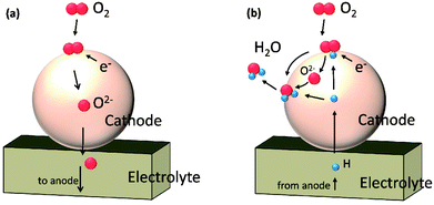 | ||
| Fig. 1 Schematic diagrams of cathode reactions on Sr3Fe2O7−δ operating in O-SOFCs (a) and P-SOFCs (b), respectively. | ||
Computational methods
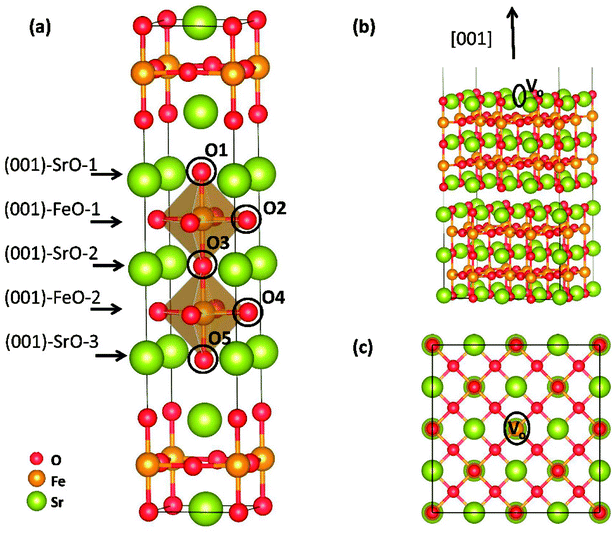
Theoretical study was conducted to reveal the O2 reduction reaction process over Sr3Fe2O7 (001) surface using the projector augmented wave (PAW) method, implemented in the Vienna ab initio simulation package (VASP).17–19 Perdew–Berke–Ernzelhoff (PBE) generalized gradient approximation was adapted to treat the exchange–correlation effects.20 Kinetic energy cutoff set was 450 eV and energy convergence criterion was set to 10−5 eV per atom. Structural optimization was carried out until the Hellmann–Feynman force on each atom was lower than 0.03 eV Å−1. All calculations were spin-polarized,21,22 and the ferromagnetic (FM) states instead of antiferromagnetic (AFM) were used as indicated by Tadashi Ota et al.23 To predict the electronic structures more precisely, DFT + U method24 was applied in all our calculations. Here, the value of Ueff = U − J = 5.3 eV was applied for Fe ions, and the Coulomb (U) and exchange (J) parameters were not taken into account separately.12,25 An elementary crystal structure containing 24-atoms was established for SFO, as shown in Fig. 2(a). Parameters of the tetragonal unit cell are calculated as a = b = 3.8873 Å and c = 20.2442 Å, in good agreement with experimental results (space group I4/mmm, a = b = 3.8668 Å and c = 20.1737 Å (ref. 26)).As previously reported, (001) surface is more stable than (100), (110), (111), and (011) surfaces in SFO,16 and therefore, five ten-layer (001) slabs, as shown in Fig. S1,† were cleaved to simulate the terminal surface and to intensively seek the suitable terminal surface for later reaction mechanism investigation. Here, a 5 × 5 × 1 k-points mesh was adapted using the Monkhorst–Pack scheme to sample the Brillouin zone integration.27 To investigate O2 adsorption and dissociation reactions, a 2√2 × 2√2 surface (001) slab was built to make a bigger surface system with 192 atoms (as shown in Fig. 2(b) and (c)). To save the computing resources, these calculations were performed with 2 × 2 × 1 k-points grid. Transition states (TSs) of oxygen dissociation and ion migration were calculated through the climbing image nudged elastic band (CI-NEB) method.28 All the slabs were separated perpendicularly by a 15 Å vacuum space, and the bottom-two layers were fixed to their bulk position, while the other atoms were allowed to fully relax. Dipole correction was applied to the direction perpendicular to the surface.
Adsorption energy of reactants was calculated using Eads = E[slab+reactant] − E[slab] − E[reactant], where the E[slab+reactant], E[slab] and E[reactant] denoted the total energy of the reactant adsorbed surface, the pristine surface and the gas phase reactant, respectively. So, a positive value of Eads suggests that the adsorption reaction is endothermic, while a negative one indicates an exothermic reaction. Formation energy (Evac) of an oxygen vacancy was calculated according to Evac = E[defective] + 1/2E[O2] − E[perfect], where E[defective] and E[perfect]were the total energy of defective and perfect Sr3Fe2O7 surfaces, respectively. Proton formation energy (Ehyrd) was calculated using the equation: Ehyrd = 2EOH − Evac + Ept, where EOH was the energy associated with substitution of O2− with an OH− group, Evac was the energy needed to create an oxygen vacancy, and Ept was the energy of the gas phase reaction: H2 + 1/2O2 = H2O. Ept was calculated to be −2.52 eV. The ground state triplet O2 was used for oxygen adsorption and dissociation, and the value of evaluated bond length was fit as 1.233 Å, which agreed with the experimental results of 1.207 Å.
Results and discussion
Properties of Sr3Fe2O7
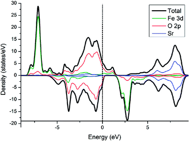
Electronic density of state (DOS) of SFO, with the smear value of 0, and the sigma value of 0.1 in VASP, are displayed in Fig. 3. Fe 3d electrons arise significantly around the Fermi energy level and hybridize with the 2p electrons of the O, indicating an increase of the charge-carrier concentration. The conducting characteristics of Sr3Fe2O7 is half-metallic, in good agreement with previous experimental and theoretical investigations on Sr3Fe2O7, facilitating the electron conduction.12,23,29,30To explore stable (001) surface for O2 reduction investigation, five types of (001) terminal surfaces can be clave, as illustrated in Fig. 2 and S1† and noted as SrO-1, SrO-2, SrO-3, FeO-1 and FeO-2 terminal surfaces, respectively. Surface energies (Esur) of SrO-1, SrO-2, SrO-3, FeO-1 and FeO-2 terminal surfaces are calculated as 7.69, 12.98, 19.06, 18.90 and 13.94 eV Å−2, respectively. Among these surfaces, SrO-1 terminal surface has much lower Esur than the others, indicating that it is the most stable one. And therefore, our later investigations on O2 reduction reaction are mainly focused on SrO-1 terminal surface.
Oxygen vacancy formation energy (Evac) and proton formation energy (Ehyrd) on SrO-1 surface (at O1 site, as indicated in Fig. 2(a)) are calculated as 0.77 and −2.26 eV, respectively. The extremely negative value of Ehyrd on SrO-1 terminal surface indicates that protons tend to automatically form in wet atmosphere with no need of additional energy input. Evac and Ehyrd at SrO-2 and FeO-2 terminal surfaces (with relatively low surface energies) are also calculated. As summarized in Table 1, within the investigated terminal surfaces, SrO-1 terminal surface has the lowest Ehyrd value, while SrO-2 has the lowest Evac value. These results are consistent with our previous investigations on Evac and Ehyrd calculated at different O positions (as shown in Fig. 2(a)) in SFO bulk,12 suggesting that protons are more easily to locate at rock-salt layer while oxygen vacancies at the central of perovskite layers. Moreover, compared with those in Sr3Fe2O7 bulk model,12,16 values of Evac and Ehyrd are much lower for surfaces, suggesting that oxygen vacancies and protons are more easily to form at surface than in bulk.
| Esur (eV) | Evac–surf (eV) | Evac–bulk (eV) | Ehyrd–surf (eV) | Ehyrd–bulk (eV) | |
|---|---|---|---|---|---|
| SrO-1/O1 | 0.48 | 0.77 | 1.57 | −2.26 | −1.44 |
| SrO-2/O3 | 0.81 | 0.47 | 0.53 | −1.52 | −0.23 |
| FeO-2/O4 | 0.87 | 1.00 | 1.10 | −0.65 | −0.34 |
| LSCF(001) | 1.15 | 2.66 | — | 3.59 | — |
As comparison, (001) terminal surface of La0.5Sr0.5Co0.25Fe0.75O3 (LSCF) are also built, as shown in Fig. S2.† Calculation parameters of LSCF surface are set based on literature.31 It should be noticed that in some recent studies, SrO terminal surfaces were applied for LSCF on account of Sr2+ segregation.32,33 Yet, such Sr segregation were usually experimentally observed after heating at intermediate temperatures (600–800 °C) for at least tens of hours and could be aggravated at the presence of Cr2O3 or electrochemical forces.32–36 While on fresh LSCF sintered at 1350–1400 °C for 4–5 hours, no Sr segregation were spotted.32–34 Moreover, XPS analysis on the surface composition of pretested LSCF cathode indicated that its Sr/(La + Sr) ratios (∼0.43) were reasonably close to the desired values (0.4).36 In this work, emphasis is put on investigating the native catalytic ability of SFO cathode toward oxygen reduction reaction in O-SOFC and in P-SOFC with LSCF as a comparison. And therefore, LSCF computational model is built based on its original composition without considering the Sr segregation as some studies suggested.32,33 Moreover, to get good compare with SrO-1 terminal surface (most stable surface) in Sr3Fe2O7, LaSrO (001) terminal surface of LSCF is adopted for catalytic activity investigation.37,38 LSCF (001) surface has a surface energy of 1.15 eV, higher than those of SFO (001) surface, as shown in Table 1. Importantly, Evac and Ehyrd on this surface are 2.66 and 3.59 eV, respectively, much higher than those of SFO, indicating that these defects are harder to generate in LSCF than in SFO. The large Evac and Ehyrd values in LSCF may root in its high La atom content in surface22 and its perovskite structure. Moreover, the extremely high value of Ehyrd on LSCF surface suggests that it is impossible to form proton defects even at high temperatures. And therefore, in P-SOFCs, LSCF has to work as composite cathodes to effectively accelerate cathode reactions.
O2 reduction on the SrO-1 terminal surface in O-SOFCs
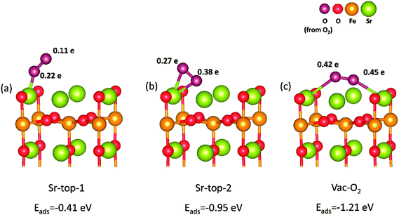
Based on above results, we can find that SrO-1 terminal surface is the most stable surface, and can energetically benefit the formations of oxygen vacancies and protons defect. And therefore, SrO-1 terminal surface is chosen for our later investigations on oxygen reduction reactions in both O-SOFCs and P-SOFCs.In O-SOFCs, cathode-reaction processes begin with oxygen adsorption and dissociation on the surface, as illustrated in Fig. 1(a). On defect SrO-1 terminal surface which contains one oxygen vacancy (as shown in Fig. 2(b)), there are three possible active sites for O2 adsorption, as shown in Fig. 4, which can be indicated as Sr-top1, Sr-top2 and Ovac-top, respectively. The adsorption energies, O–O bond lengths and atomic charges of adsorbed oxygen species are calculated and summarized in Table 2. As shown in Table 2, values of O2 adsorption energies on Sr-top1, Sr-top2 and Ovac-top are about −0.41, −0.95 and −1.21 eV, respectively. These negative values indicate that adsorption of O2 molecules on the Sr3Fe2O7 (001) surface is an exothermal reaction. Especially, adsorption energy at Ovac-top is much larger than those at Sr sites, suggesting that surface oxygen defect is energetically more favorable for O2 adsorption than Sr ions. Adsorption energies of O2 over perfect SrO-1 terminal surface are also conducted as shown in Fig. S3,† of which the largest adsorption energy is only −0.47 eV. The low adsorption energy on perfect surface further suggest that existence of surface oxygen vacancy is very important for O2 adsorption.
| Species | Eads (eV) | rO–O (Å) | Atomic charge (e) | Assignment | ||||
|---|---|---|---|---|---|---|---|---|
| O1 | O2 | Osum | ||||||
| With oxygen vacancy | SFO-0H | Sr-top-1 | −0.41 | 1.27 | 0.22 | 0.11 | 0.33 | Superoxide |
| Sr-top-2 | −0.95 | 1.33 | 0.27 | 0.38 | 0.65 | Superoxide | ||
| Vac-O2 | −1.21 | 1.35 | 0.45 | 0.42 | 0.87 | Peroxide | ||
| SFO-2H | Sr-top | −0.92 | 1.32 | 0.38 | 0.30 | 0.68 | Superoxide | |
| Vac-O2 | −1.29 | 1.36 | 0.40 | 0.51 | 0.91 | Peroxide | ||
| SFO-4H | Sr-top | −0.99 | 1.34 | 0.41 | 0.35 | 0.76 | Superoxide | |
| Vac-O2 | −1.39 | 1.37 | 0.41 | 0.52 | 0.93 | Peroxide | ||
| LSCF | −1.52 | 1.47 | 0.72 | 0.74 | 1.46 | Peroxide | ||
| Without oxygen vacancy | SFO-0H | Sr-top-1 | −0.22 | 1.26 | 0.06 | 0.21 | 0.27 | Superoxide |
| Sr-top-2 | −0.47 | 1.27 | 0.13 | 0.18 | 0.31 | Superoxide | ||
| SFO-2H | Sr-top-1 | −0.37 | 1.26 | 0.15 | 0.14 | 0.29 | Superoxide | |
| Sr-top-2 | −0.54 | 1.30 | 0.36 | 0.19 | 0.55 | Superoxide | ||
Bader charges40 of the adsorbed O2 species are summarized in Table 2, which could provide qualitative analysis on their bonding strength to the surface. Different electrons are obtained for the adsorbed O2 species which depend largely on their adsorption sites and their relative positions. Largest charge (0.87 e) of oxygen atom is observed when O atoms bonding to Sr atom over the Ovac-top site (Fig. 4(c)). This is consist with the above adsorption energy results, and indicates further the great promotion effect of oxygen vacancy on O2 adsorption reaction. When the oxygen adsorbs on LSCF (001) surface, the calculated charge of oxygen atom is 1.46 e. Since these charges go into the antibonding orbital of the oxygen molecule, the O-O is easy to break in this case. This means that it's easier for oxygen to dissociate on LSCF than on SFO surface.
Minimum energy pathway for O2 dissociation on the defect SFO (001) surface are then explored based on the Climbing Image Nudged Elastic Band (CI-NEB). As shown in Fig. 5(a), O2 adsorbs automatically over oxygen vacancy on SrO-1 surface, releasing 1.21 eV heat; then, the adsorbed O2 dissociates with one oxygen atom incorporating the neighboring oxygen vacancy, and in this process an energy barrier of 2.28 eV needs to overcome; and finally, the oxygen atom bonding above Sr sites migrate to a more stable site without overcoming any energy barrier. In the whole process, O2 dissociation should be the rate-determining step because of its large energy barrier.
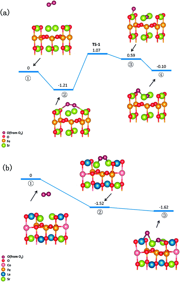 | ||
| Fig. 5 Potential energy diagram for oxygen reduction on (a) SrO-1 terminal surface of Sr3Fe2O7 cathode and (b) LSCF (001) terminal surface in O-SOFCs. | ||
Notably, when O2 adsorbs over similar LSCF (001) terminal surface, no energy barrier need to be overcome within the whole reactions (as shown in Fig. 5(b)), indicating that O2 dissociation over LSCF surface is very fast and should not be the rate-limiting steps. Previous studies on defect LSCF surface indicates that La and Sr ions have similar activity towards O2 adsorption and dissociation, which are much lower than those of Fe and Co ions.41 Since no active ions such Fe or Co on both LSCF (001) surface and SrO-1 terminal surface, such different energy barrier for O2 dissociation in these two surfaces may be related to their crystal structures, surface energies and defects formation energies. It is suggested that to improve catalytic activity of R–P cathodes towards O2 dissociation will be very effective to accelerate O2 reduction process in O-SOFCs.
It should be noted that after O2 dissociation, the formed oxygen ions need to migrate through surface or bulk of cathode to electrolyte to release the oxygen vacancy and to fulfill the cathode reactions. Surface effects on the diffusions of oxygen ions (in opposite diffusion direction with oxygen vacancies) are investigated, as shown in Fig. S4† ([001] direction) and Fig. S5† ([100] direction). Data in Table S1† clearly indicates that SrO-1 surface has a possible effect on the diffusion of oxygen ions, which largely lowers the energy barrier for O ions from 1.40 eV to 1.04 eV. Moreover, an energy barrier as low as 0.35 eV is observed for oxygen diffusion within SrO-1 terminal surface, suggesting that oxygen ions is anisotropic in SFO. Notably, energy barriers for oxygen diffusion in LSCF is about 1.96 eV, higher than those in SFO. The relatively lower oxygen vacancies form energy and lower energy barrier for oxygen diffusion makes SFO have a better oxygen ion conduction than LSCF, which is good agreement with experimental investigations.16
In conclusion, compared with perovskite oxides, SFO cathode has low oxygen vacancies formation energies and low ion diffusion energy barriers, which can bring forth excellent oxygen ion conduction. Nevertheless, its high energy barrier for O2 dissociation may restrict its application as an excellent cathode in O-SOFCs. To improve the catalytic activity of SFO via structure or composition modifications will be the key. Also, the different conducting properties and catalytic activities of SFO and LSCF clearly indicate their different rate-limiting steps in cathode reactions in O-SOFCs.14
Cathode reaction in P-SOFCs
In P-SOFCs, cathode reactions may include the following steps: (1) protons generated at anode transfer to the surface of SFO cathode via diffusion; (2) O2 molecules adsorbs on the SFO cathode surface, and then dissociate with the presence of protons; (3) protons react with the dissociated O2 to form water molecules; and finally, (4) the formed water molecules is released from the cathode surface to the gas atmosphere. As shown in eqn (2), four protons are needed to react completely with one oxygen molecule. To theoretically investigate the cathode reaction paths, two surfaces containing two or four protons are used, respectively, as shown in Fig. 8 and 9. For the former, the other two protons needed in reactions are locating at the second layer of the surface. And to distinguish the amount of surface protons, SrO-1 surface with protons are denoted as SrO-1-xH, where the x indicates the number of protons on the surface.The proton conduction in the Sr3Fe2O7 cathode
Cathode reaction in P-SOFCs starts from the proton diffusion, which are also suggested as one of the rate-limiting steps in composite cathodes.12 Proton diffuse to SFO-1 surface via the combination of two typical paths: the proton intra octahedral hopping and the proton reorientation around O ions,42 as shown in Fig. 6(a) and (b), respectively. Energy barriers for the seven possible unique intraoctahedral hopping and four proton reorientations are summarized in Tables 3 and 4. Protons transferring across the rock-salt layer (O6 to O5) is most difficult process, which needs to overcome the highest energy barrier of 0.67 eV. This value is in the same range for proton conductions in proton conducting electrolytes, such as Y-doped BaZrO3 (0.08–1.35 eV)43 and BaZr0.75Co0.25O3 (0.01–0.63 eV).15 The low energy barrier for proton migration and the low proton formation energy strongly suggest the SFO system is good proton conduction containing cathode material.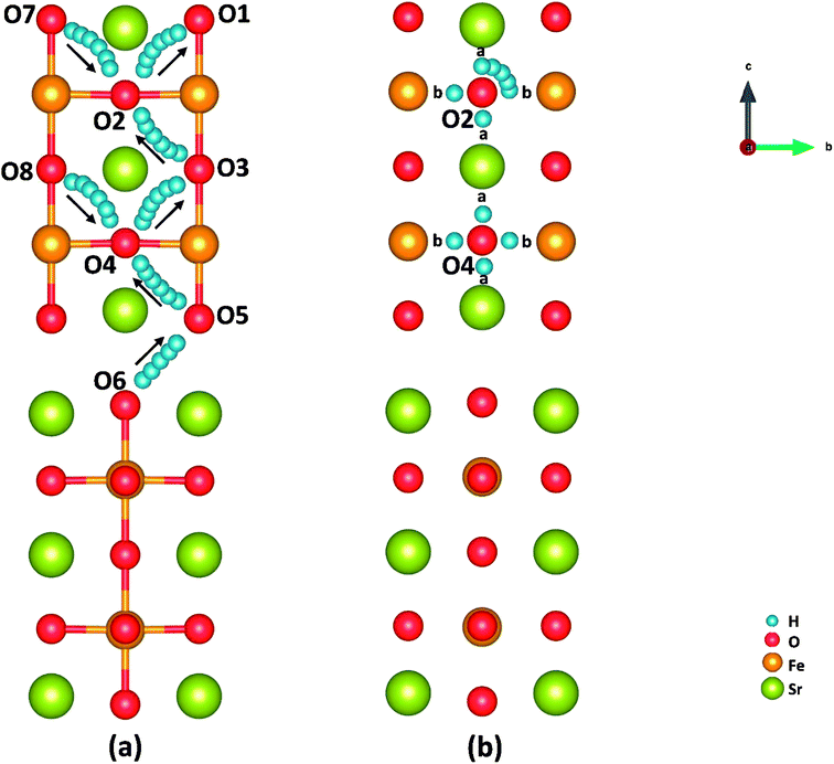 | ||
| Fig. 6 Illustration of (a) proton intraoctahedral hopping pathways and (b) the proton reorientation around O. | ||
| Octahedron transfer path | Energy barriers/eV | ||
|---|---|---|---|
| Surface | Bulk | BaZr0.75Co0.25O3 | |
| O6 to O5 | 0.67 | 0.62 | 0.03–0.63 |
| O5 to O4 | 0.34 | 0.53 | |
| O4 to O3 | 0.04 | 0.05 | |
| O3 to O2 | 0.31 | 0.25 | |
| O2 to O1 | 0.14 | 0 | |
| O7 to O2 | 0.62 | 0.53 | |
| O8 to O4 | 0.28 | 0.25 | |
| Reorientation path | Energy barriers/eV | ||
|---|---|---|---|
| Surface | Bulk | BaZr0.75Co0.25O3 | |
| O2(a) to O2(b) | 0.44 | 0.32 | 0.05–0.26 |
| O2(b) to O2(a) | 0.07 | 0.25 | |
| O4(a) to O4(b) | 0.24 | 0.27 | |
| O4(b) to O4(a) | 0.12 | 0.08 | |
As shown in Fig. 6 and Table 3, the energy barriers for protons hopping along the [010] direction (O8 → O4 → O3) are far smaller than those for [001] direction (O6 → O5 → O4 → O3 → O2 → O1), indicating that proton transferring in surface mode is also anisotropic as that in bulk.15 However, the energy barriers for proton hopping in surface model are similar to those obtained in bulk model, indicating that the surface effect on proton transferring is not as obvious as that on oxygen diffusion (as shown in Tables S2 and S3†). Moreover, when the proton is hopping away from an oxygen ion locating at Sr-O layer, the energy barrier is relatively high, while relatively low in the opposite process. It's found that the effective charge of H atoms (−0.34 e in SrO layer and −0.22 e in FeO layer) and the bond length of O–H (0.96 Å in SrO layer and 1.08 Å in Fe–O layer) differ with the positions of proton defects. These suggest a relatively strong bonding of proton defects with O in Sr–O layer, which attributes to the trapping effect44–46 of the SrO layer on proton transferring as other studies.12 This property makes protons hop to outer surface with a small energy barrier (0.14 eV), which provides support for our SrO-1-2H model.
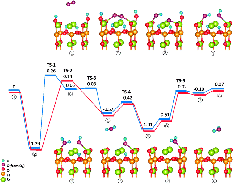
Reactions on the SrO-1 terminal surface with two surface proton present (SrO-1-2H)
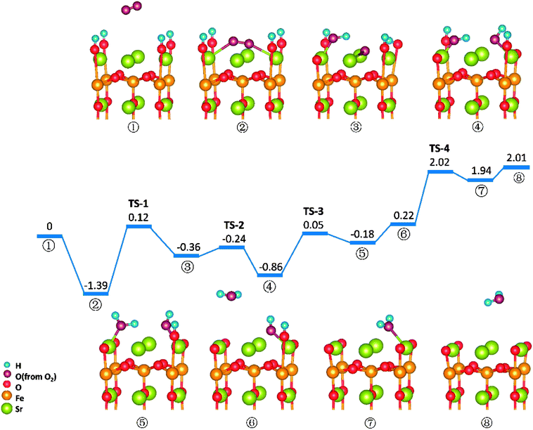
Similar to those in O-SOFCs, O2 adsorbing over the oxygen vacancy is the most stable configuration of O2 on SrO-1-2H surface with one oxygen vacancy, as shown in Fig. 7-② and Fig. S6.† The adsorption energy of such configuration is −1.29 eV, larger than that without presence of protons (−1.21 eV in Fig. 4). Meanwhile, the O2 adsorption energies on the SrO-1-2H surface with no oxygen vacancy are simulated. As shown in Table .2, the largest O2 adsorption energy is −0.54 eV, also larger than that on perfect SrO-1 surface (−0.47 eV) with no protons present. These results clearly suggest that presence of protons on SrO-1 surface could promote the adsorption of oxygen molecule.In regards to O2 dissociation and water formation process, two potential paths are mapped on SrO-1-2H surface denoted by red and blue line, respectively, as shown in Fig. 7. In path-1 (blue line), detailed reaction processes can be described as: (1) the first proton (left side in ②) migrates to the adsorbed O2 molecule and activate the dissociation of O2 molecule to form one hydroxyl (③); (2) the second proton (right side in ③) attaches to the right oxygen ion forming a new hydroxyl incorporating in the former address of oxygen vacancy (④) with a negligible energy barrier of 0.03 eV (TS-3) and releases 0.62 eV heat; 3) the proton locating at the second layer transfer to the surface and then react with the first hydroxyl to form an adsorbed water molecule (⑤) which then desorbs from the surface to gas atmosphere (⑥); 4) and finally, the second water molecular forms via the reaction of the last proton with another hydroxyl (⑦), and is released to the gas (⑧). Throughout the whole reaction process, O2 dissociation is still the one needing to overcome the largest energy barrier of 1.55 eV (TS-1). Fortunately, compared to those in O-SOFCs (energy barrier of 2.28 eV), the energy barrier here is much depressed, indicating that the hydrogenated surface can obviously accelerate the O2 reduction processes.
The main divergence between path-1 and path-2 lies in the way for protons on surface to react with the O2. In path-2 (red line), the cathode reaction begins with two protons simultaneously attaching to the oxygen molecule to dissociate O2, and thus, generating two hydroxyls concurrently. In this process, an energy barrier of 1.43 eV need to be overcome, slightly lower than that in path-1. This seems to suggest that two protons react with the oxygen molecule at the same time is more effective than that react one by one.
It is worth mentioning that direct formation of the first water via the reaction of adsorbed oxygen ion and the two surface protons is not observed in our DFT calculation process. This may root in its unstable structure in energy because of the contest of the two dissociated O atoms for the protons.
Reactions on the SrO-1 terminal surface with four surface proton defects present (SrO-1-4H)
O2 reduction reactions on SrO-1-4H surface are shown in Fig. 8. In this model, all four protons required in oxygen reduction reaction (as shown in eqn (2)) locate at SrO-1 terminal surface. And reaction processes in this path (path-3) occur in sequence as: (1) O2 adsorbs on the Ovac-top site (②); (2) one proton diffuses to the adsorbed O2 molecule and forms a hydroxyl (③) by surmounting an energy barrier of 1.51 eV, similar to that in path 1; (3) the second proton (on the opposite site of the first hydroxyl) transfers to the dissociated oxygen ion to form another hydroxyl (④); (4) the first water molecule forms via the reaction of the third proton with the first hydroxyl (⑤), which is then released to gas (⑥); (5) the second water molecule forms with a large energy barrier of 1.80 eV (TS-4) to be overcome, and then desorbs to gas phase.In this path, the dissociation of O2 and the formation of second water molecule, need to over large energy barriers. Moreover, compared with the energy map for SrO-1-2H surface (Fig. 7), the formation energy barriers for the water molecule, especially the second one, are extremely high on SrO-1-4H surface, suffering from the competition of neighboring surface oxygen ions for protons. These seem to suggest that existence of too many protons at surface is unfavorable to the formation of water. This along with that presence of oxygen vacancy favoring for O2 adsorption implies that steam pressure in testing atmosphere should not be too much to achieve high performance, and that coexistence of suitable concentrations of protons, oxygen vacancies and electron defects (triple conducting) should be of key importance for cathode reactions in P-SOFC.
Comparing the SFO performance in O-SOFC and P-SOFC, our DFT calculation also reveals that SFO shows a large energy barrier (∼2.28 eV) for oxygen dissociation reaction in O-SOFC, while in P-SOFCs, such energy barrier has been greatly depressed at the presence of protons (1.43–1.57 eV). This is in good agreement with experimental observation that SFO is more effective than both LSCF and LSCF-BZCY as a cathode for P-SOFCs; while for O-SOFCs, opposite is the case.12,16
Moreover, DFT investigations suggest that the high proton formation energy of LSCF makes it unfavorable for proton formation, and therefore, composite cathodes consisting LSCF and proton conductors (for example, BZCY) have to be made up to effectively accelerate cathode reactions.
Conclusions
In summary, a comprehensive DFT calculation was performed, which studied the O2 reduction on the SFO (001) surface working in both O-SOFCs and P-SOFCs. Most feasible paths for cathode reaction over the SrO-1 surface are summarized in Fig. 9(a) for O-SOFCs and Fig. 9(b) for P-SOFCs.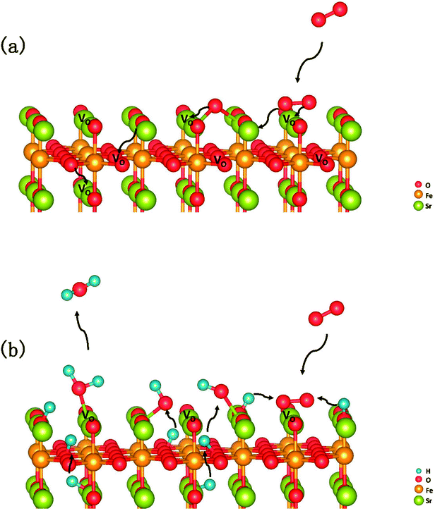 | ||
| Fig. 9 Schematic diagram of the most feasible reaction model over the Sr3Fe2O7−δ cathode for oxygen conducting SOFCs (a) and proton conducting SOFCs (b). | ||
In O-SOFCs, adsorption of O2 on the SFO surface goes smoothly, while O2 dissociation occurs with a high energy barrier (2.19 eV) that needs to be overcome, which greatly limits the cathode reaction rates of SFO. And therefore, to improve cathode performance of SFO, it is key to improve its catalytic activity toward O2 dissociation. In P-SOFCs, existence of protons benefits the dissociation of O2, which effectively lowers the energy barriers to about 1.43 eV. Yet, when four protons needed in cathode reactions all locate at the SFO surface, the energy barrier for steam formation increased largely from 0.59 eV to 1.80 eV. This result seems to indicate that overranging steam concentrations in the testing atmosphere may have a negative effect on cell performance for the reduction of oxygen vacancies and the high energy barrier for water formation.
Conflicts of interest
There are no conflicts to declare.Acknowledgements
This work was financially supported by the National Key Research and Development Program of China (2017YFA0402800), the Natural Science Foundation of China (51472228, 51627901), the External Cooperation Program of BIC, Chinese Academy of Sciences (211134KYSB20130017), Hefei Science Center CAS (2016HSC-IU004), and the Fundamental Research Funds for the Central Universities (WK3430000004).Notes and references
- S. Choi, S. Yoo, J. Kim, S. Park, A. Jun, S. Sengodan, J. Kim, J. Shin, Y. J. Hu and Y. M. Choi, Highly efficient and robust cathode materials for low-temperature solid oxide fuel cells: PrBa0.5Sr0.5Co2−xFexO5+δ, Sci. Rep., 2013, 3, 2426 CrossRef PubMed.
- T. Wei, Y. H. Huang, R. Zeng, L. X. Yuan, X. L. Hu, W. X. Zhang, L. Jiang, J. Y. Yang and Z. L. Zhang, Evaluation of Ca3Co2O6 as cathode material for high-performance solid-oxide fuel cell, Sci. Rep., 2013, 3, 1125 CrossRef PubMed.
- T. Tsai and S. A. Barnett, Effect of LSM–YSZ cathode on thin-electrolyte solid oxide fuel cell performance, Solid State Ionics, 1997, 93(3–4), 207–217 CrossRef.
- J. Harris, C. Metcalfe, M. Marr, J. Kuhn and O. Kesler, Fabrication and characterization of solid oxide fuel cell cathodes made from nano-structured LSCF–SDC composite feedstock, J. Power Sources, 2013, 239(239), 234–243 CrossRef.
- B. Wei, L. Zhe, X. Huang, S. Li, G. Ai, Z. Liu and W. Su, Electrochemical characteristics of Ba0.5Sr0.5Co0.8Fe0.2O3−δ–Sm0.2Ce0.8O1.9 composite materials for low-temperature solid oxide fuel cell cathodes, Mater. Lett., 2006, 60(29), 3642–3646 CrossRef.
- L. Yang, Z. Liu, S. Wang, Y. M. Choi, C. Zuo and M. Liu, Mixed Proton-Oxide Ion-Electron Conducting Cathode for SOFCs Based on Oxide Proton Conductors, J. Power Sources, 2010, 195(2), 471–474 CrossRef.
- L. Yang, C. Zuo, S. Wang, Z. Cheng and M. Liu, A Novel Composite Cathode for Low-Temperature SOFCs Based on Oxide Proton Conductors, Adv. Mater., 2010, 20(17), 3280–3283 CrossRef.
- C. Duan, J. Tong, M. Shang, S. Nikodemski, M. Sanders, S. Ricote, A. Almansoori and R. O'Hayre, Readily processed protonic ceramic fuel cells with high performance at low temperatures, Science, 2015, 349(6254), 1321–1326 CrossRef PubMed.
- M. Shang, J. Tong and R. O'Hayre, A promising cathode for intermediate temperature protonic ceramic fuel cells: BaCo0.4Fe0.4Zr0.2O3−δ, RSC Adv., 2013, 3(36), 15769–15775 RSC.
- Z. Tao, L. Bi, L. Yan, W. Sun, Z. Zhu, R. Peng and W. Liu, A novel single phase cathode material for a proton-conducting SOFC, Electrochem. Commun., 2009, 11(3), 688–690 CrossRef.
- Y. Rao, S. Zhong, H. Fei, Z. Wang, R. Peng and Y. Lu, Cobalt-doped BaZrO3: A single phase air electrode material for reversible solid oxide cells, Int. J. Hydrogen Energy, 2012, 37(17), 12522–12527 CrossRef.
- Z. Wang, W. Yang, S. P. Shafi, L. Bi, Z. Wang, R. Peng, C. Xia, W. Liu and Y. Lu, A high performance cathode for proton conducting solid oxide fuel cells, J. Mater. Chem. A, 2015, 3(16), 8405–8412 RSC.
- Y. Choi, M. C. Lin and M. Liu, Computational study on the catalytic mechanism of oxygen reduction on La(0.5)Sr(0.5)MnO(3) in solid oxide fuel cells, ChemInform, 2007, 46(38), 7214–7219 Search PubMed.
- Y. L. Lee, J. Kleis, J. Rossmeisl, Y. Shao Horn and D. Morgan, Prediction of solid oxide fuel cell cathode activity with first-principles descriptors, Energy Environ. Sci., 2011, 4(10), 3966–3970 RSC.
- Z. Wang, W. Yang, Z. Zhu, R. Peng, X. Wu, C. Xia and Y. Lu, First-principles study of O2 reduction on BaZr1−xCoxO3 cathodes in protonic-solid oxide fuel cells, J. Mater. Chem. A, 2014, 2(39), 16707–16714 RSC.
- D. Huan, Z. Wang, Z. Wang, R. Peng, C. Xia and Y. Lu, High-Performance Cathode with a Two-Layered R–P Structure for Intermediate Temperature Solid Oxide Fuel Cells, ACS Appl. Mater. Interfaces, 2016, 8(7), 4592–4599 CrossRef PubMed.
- B. Pe, Projector augmented-wave method, Phys. Rev. B: Condens. Matter Mater. Phys., 1994, 50(24), 17953–17979 CrossRef.
- B. Morgan, D. Scanlon and G. Watson, Small polarons in Nb- and Ta-doped rutile and anatase TiO2, J. Mater. Chem., 2009, 19(29), 5175–5178 RSC.
- G. Kresse and J. Furthmüller, Efficiency of ab initio total energy calculations for metals and semiconductors using a plane-wave basis set, Comput. Mater. Sci., 1996, 6(1), 15–50 CrossRef.
- J. P. Perdew, K. Burke and M. Ernzerhof, Generalized Gradient Approximation Made Simple, Phys. Rev. Lett., 1996, 77(18), 3865–3868 CrossRef PubMed.
- Y. A. Mastrikov, M. M. Kuklja, E. A. Kotomin and J. Maier, First-principles modelling of complex perovskite (Ba1−xSrx)(Co1−yFey)O3−δ for solid oxide fuel cell and gas separation membrane applications, Energy Environ. Sci., 2010, 3(10), 1544–1550 RSC.
- Y. A. Mastrikov, R. Merkle, E. A. Kotomin, M. M. Kuklja and J. Maier, Formation and migration of oxygen vacancies in La Sr Co Fe O perovskites: insight from calculations and comparison with Ba Sr Co Fe O, Phys. Chem. Chem. Phys., 2012, 15(3), 911–918 RSC.
- T. Ota, H. Kizaki and Y. Morikawa, Mechanistic Analysis of Oxygen Vacancy Formation and Ionic Transport in Sr3Fe2O7−δ, J. Phys. Chem. C, 2018, 122(8), 4172–4181 CrossRef.
- S. L. Dudarev, G. A. Botton, S. Y. Savrasov, C. J. Humphreys and A. P. Sutton, Electron-energy-loss spectra and the structural stability of nickel oxide: An LSDA + U study, Phys. Rev. B, 1998, 57(3), 1505–1509 CrossRef.
- G. Sürücü and A. Erkişi, The investigation of electronic and thermo-elastic properties of lanthanum orthoferrite (LaFeO3), Perovskite, 2017, 25, 1–19 Search PubMed.
- A. A. Markov, M. V. Patrakeev, V. V. Kharton, Y. V. Pivak, I. A. Leonidov and V. L. Kozhevnikov, Oxygen Nonstoichiometry and Ionic Conductivity of Sr3Fe2−xScxO7−δ, ChemInform, 2007, 19(16), 3980–3987 Search PubMed.
- H. J. Monkhorst, Special points for Brillouin-zone integrations, Phys. Rev. B: Condens. Matter Mater. Phys., 1976, 16(4), 1748–1749 Search PubMed.
- G. Henkelman, B. P. Uberuaga and H. Jónsson, A climbing image nudged elastic band method for finding saddle points and minimum energy paths, J. Chem. Phys., 2000, 113(22), 9901–9904 CrossRef.
- Y. Ling, T. Guo, X. Zhang, R. A. Budiman, Y. Fujimaki, T. Nakamura, B. Lin, T. Kawada and K. Amezawa, Evaluation of electrical conductivity and oxygen diffusivity of the typical Ruddlesden–Popper oxide Sr3Fe2O7−δ, Ceram. Int., 2017, 43(18), 16264–16269 CrossRef.
- P. Adler, Electronic State, Magnetism, and Electrical Transport Behavior of Sr3−xAxFe2O7(x ≤ 0.4, A = Ba, La), J. Solid State Chem., 1997, 130(1), 129–139 CrossRef.
- A. M. Ritzmann, J. M. Dieterich and E. A. Carter, Density functional theory + U analysis of the electronic structure and defect chemistry of LSCF (La0.5Sr0.5Co0.25Fe0.75O3−δ), Phys. Chem. Chem. Phys., 2016, 18(17), 12260 RSC.
- L. Zhao, J. Drennan, C. Kong, S. Amarasinghe and S. P. Jiang, Insight into surface segregation and chromium deposition on La0.6Sr0.4Co0.2Fe0.8O3−δ cathodes of solid oxide fuel cells, J. Mater. Chem. A, 2014, 2(29), 11114–11123 RSC.
- J. Druce, H. Téllez, M. Burriel, M. D. Sharp, L. J. Fawcett, S. N. Cook, D. S. Mcphail, T. Ishihara, H. H. Brongersma and J. A. Kilner, Surface termination and subsurface restructuring of perovskite-based solid oxide electrode materials, Energy Environ. Sci., 2014, 7(11), 3593–3599 RSC.
- D. Oh, D. Gostovic and E. D. Wachsman, Mechanism of La0.6Sr0.4Co0.2Fe0.8O3 cathode degradation, J. Mater. Res., 2012, 27(15), 1992–1999 CrossRef.
- M. E. Lynch, L. Yang, W. Qin, J. J. Choi, M. Liu, K. Blinn and M. Liu, Enhancement of La0.6Sr0.4Co0.2Fe0.8O3−δ durability and surface electrocatalytic activity by La0.85Sr0.15MnO3±δ investigated using a new test electrode platform, Energy Environ. Sci., 2011, 4(6), 2249–2258 RSC.
- S. P. Simner, M. D. Anderson, M. H. Engelhard and J. W. Stevenson, Degradation mechanisms of La-Sr-Co-Fe-O3SOFC cathodes, Electrochem. Solid-State Lett., 2006, 9(10), A478–A481 CrossRef.
- M. Wei, H. Li, G. Guo, Y. Liu and D. Zhang, Effects of PdO modification on the performance of La0.6Sr0.4Co0.2Fe0.8O3−δ cathodes for solid oxide fuel cells: A first principle study, Int. J. Hydrogen Energy, 2017, 42(36), 23180–23188 CrossRef.
- A. Longo, L. F. Liotta, D. Banerjee, V. L. Parola, F. Puleo, C. Cavallari, C. J. Sahle, M. M. Sala and A. Martorana, The Effect of Ni Doping on the Performance and Electronic Structure of LSCF Cathodes Used for IT-SOFCs, J. Phys. Chem. C, 2018, 122(2), 1003–1013 CrossRef.
- Y. Choi, D. S. Mebane, M. C. Lin and M. Liu, Oxygen Reduction on LaMnO3-Based Cathode Materials in Solid Oxide Fuel Cells, Chem. Mater., 2007, 19(7), 1690–1699 CrossRef.
- G. Henkelman, A. Arnaldsson and H. Jónsson, A fast and robust algorithm for Bader decomposition of charge density, Comput. Mater. Sci., 2006, 36(3), 354–360 CrossRef.
- Z. Wang, R. Peng, W. Zhang, X. Wu, C. Xia and Y. Lu, Oxygen reduction and transport on the La1−xSrxCo1−yFeyO3−δ cathode in solid oxide fuel cells: a first-principles study, J. Mater. Chem. A, 2013, 1(41), 12932–12940 RSC.
- J. A. Dawson, J. A. Miller and I. Tanaka, First-Principles Insight into the Hydration Ability and Proton Conduction of the Solid State Proton Conductor, Y and Sn Co-Doped BaZrO3, Chem. Mater., 2015, 27(3), 901–908 CrossRef.
- B. Merinov, Proton diffusion pathways and rates in Y-doped BaZrO3 solid oxide electrolyte from quantum mechanics, J. Chem. Phys., 2009, 130(19), 1021 CrossRef PubMed.
- M. S. Islam, P. R. Slater, J. R. Tolchard and T. Dinges, Doping and defect association in AZrO(3) (A = Ca, Ba) and LaMO(3) (M = Sc, Ga) perovskite-type ionic conductors, Dalton Trans., 2004, 19(19), 3061–3066 RSC.
- S. J. Stokes and M. S. Islam, Defect chemistry and proton-dopant association in BaZrO3 and BaPrO3, J. Mater. Chem., 2010, 20(30), 6258–6264 RSC.
- M. E. Björketun, P. G. Sundell, G. Wahnström and D. Engberg, A kinetic Monte Carlo study of proton diffusion in disordered perovskite structured lattices based on first-principles calculations, Solid State Ionics, 2005, 176(39), 3035–3040 CrossRef.
Footnote |
| † Electronic supplementary information (ESI) available. See DOI: 10.1039/c8ra04059a |
| This journal is © The Royal Society of Chemistry 2018 |

