 Open Access Article
Flake-like InVO4 modified TiO2 nanofibers with longer carrier lifetimes for visible-light photocatalysts
Yun Zhouab,
Lixin Liub,
Tao Wub,
Guolong Yuana,
Junyu Liab,
Qiujie Dingab,
Fugang Qia,
Wenjun Zhub,
Xiaoping OuYang*a and
Yuan Wang *b
*b
aSchool of Materials Science and Engineering, Xiangtan University, Xiangtan 411105, Hunan, China. E-mail: oyxp2003@alyun.com
bNational Key Laboratory for Shock Wave and Detonation Physics, Institute of Fluid Physics, China Academy of Engineering Physics, P.O. Box 919-111, Mianyang, Sichuan 621900, People’s Republic of China. E-mail: wangyuan0000@gmail.com
First published on 30th July 2018
Abstract
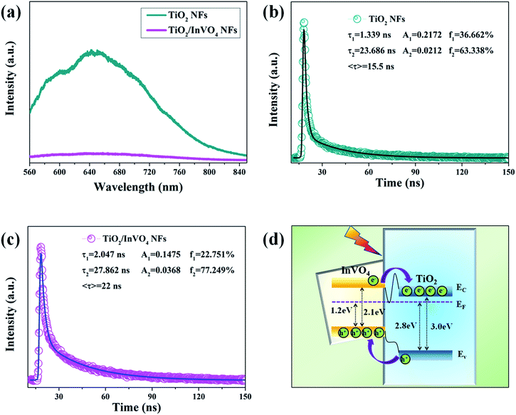
Highly efficient solar light absorption capabilities and quantum yields in photocatalysts are key to their application in photocatalytic fields. Towards this end, TiO2/InVO4 nanofibers (NFs) have been designed and fabricated successfully by a one-pot electrospinning process. The resulting TiO2/InVO4 NFs display excellent visible-light photocatalytic activity, owing to their prominent visible-light absorption and electron–hole separation properties. Time-resolved transient PL spectroscopy demonstrated that the TiO2/InVO4 NFs display longer emission decay times (22.0 ns) compared with TiO2 NFs (15.5 ns), implying that the heterojunction can remarkably suppress the electron–hole recombination and promote the carrier transfer efficiency. With tailored heterostructure features, TiO2/InVO4 NFs exhibit superior visible-light photodegradation activity, and after 80 min of visible-light irradiation, almost 95% of RhB molecules can be decomposed by TiO2/InVO4 NFs, while only 18% of RhB molecules can be decomposed by pure TiO2 NFs.
1. Introduction
Nowadays, with the overuse of various dyes and plastic products, organic pollutants in water and soil have drawn increasing attention. Among the various strategies, the development of efficient photocatalysts is a promising method for the treatment of organic pollutants, owing to its utilization of abundant solar energy, as well as its low cost and lack of secondary pollution during the course of decomposition.1–3 Since A. Fujishima discovered the interesting phenomenon of light-induced water splitting by TiO2 in the 1970s,4 TiO2 materials have been the most promising candidates for photocatalytic decontamination on account of their non-toxic, non-luminous corrosion, inert chemical properties, high photocatalytic activity, low cost, and cycle stability.5–7 However, further application of TiO2 photocatalysts is unfortunately limited by their large bandgap energy and short photogenerated carrier lifetimes.8 To overcome these limitations, persistent research, such as non-metal element or metal ion doping,9–11 surface modification,12 semiconductor/metal combination,13,14 and semiconductor/semiconductor hybridization,15–17 has been engaged in order to narrow the bandgap energy for better visible-light absorption and promote electron–hole separation for longer carrier lifetimes. Herein, constructing a TiO2-based semiconductor/semiconductor nanoheterostructured photocatalyst is an efficient method to increase visible-light harvesting and meanwhile suppress electron–hole recombination, ultimately leading to photocatalytic activity improvement.18 Up until now, many TiO2-based nanoheterostructures with excellent photocatalytic performance have been reported, such as TiO2/SnO2,19 TiO2/ZnO,20 TiO2/CdS,21 TiO2/MoS2,22 TiO2/g-C3N4,23 TiO2/CuInS2,24 etc. Therefore, designing and constructing impactful nanoheterostructures is an effectual way to extend the lifetime of the photogenerated charge, and consequently improve the photocatalytic activity.InVO4 semiconductors, as an important group of semiconductors, have attracted much interest because of their potential applications in visible-light-driven photocatalysis, photoelectrochemistry, and gas sensing.25,26 In particular, InVO4 is considered to be an ideal choice for coupling with TiO2 to improve the visible-light photocatalytic performance due to its relatively low bandgap energy (Eg ≈ 2.1 eV) and energy level matching with TiO2. Up till now, the process for fabricating TiO2/InVO4 NFs usually involves a few synthesis steps, including loading TiO2 or InVO4 particles on the surface of InVO4 or TiO2, such as via a hydrothermal method followed by an ion impregnate method.27–29 Hence, the fabrication method for TiO2/InVO4 nanoheterostructures needs to be simplified. Furthermore, although previous research has revealed that TiO2/InVO4 heterostructures exhibit enhanced UV-Vis and visible-light photocatalytic performance, in-depth analysis of the charge transfer and carrier lifetimes of the nanoheterostructure is still missing. For example, Ge et al. explored the visible-light photocatalytic performance of an InVO4–TiO2 photocatalyst synthesized by a sol–gel method, whereas further discussion on the photocatalytic improvement mechanism is absent.30 Shen and Perales-Martínez proposed a mechanism for the electron–hole separation process in TiO2/InVO4 composites only based on the energy band structure, without intuitive experimental characterization.27,28 Thus, it is necessary to further study the charge transfer and lifetime of the photogenerated charges of TiO2/InVO4 composites, and it should be clarified as to how much the heterojunction contributes to electron transport, and for how long the carrier lifetime can be obtained through separation at the interface of the heterojunction. Hence, the charge transfer mechanism and carrier lifetime of TiO2/InVO4 nanoheterostructures need to be analyzed in-depth.
In this paper, we successfully synthesized TiO2/InVO4 NFs by a one-pot electrospinning method for the first time, which could provide ample heterojunction interfaces as separation channels for photogenerated electron–hole pairs. Moreover, time-resolved transient PL spectroscopy was employed to confirm the carrier lifetime of the TiO2/InVO4 NFs. With the tailored nanoheterostructures, the prepared TiO2/InVO4 NFs exhibited enhanced photocatalytic activity due to broadened visible-light harvesting and efficiently prolonged carrier lifetimes resulting from the nanoheterojunction formed between TiO2 and InVO4.
2. Materials and methods
2.1 Synthesis of TiO2/InVO4 NFs
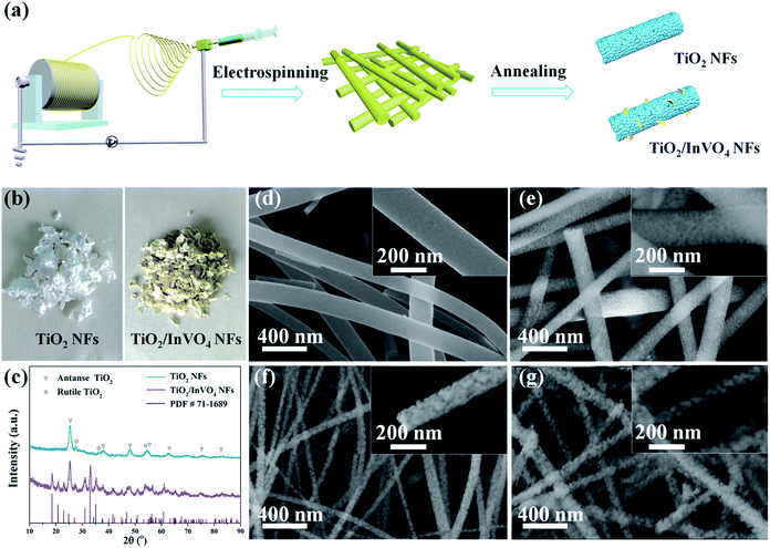
TiO2/InVO4 NFs were synthesized by a one-pot electrospinning process, as shown in Fig. 1(a). Briefly, 0.19 g In(NO3)3·4.5H2O, 0.18 g VO(acac)2, 0.68 g tetrabutyl titanate (TBT), and 0.4 g polyvinylpyrrolidone (PVP) were added into a mixed solution of 2 g dimethylacetamide (DMAC), 1.0 ml ethanol, and 0.8 ml acetic acid, after which the above solution was magnetically stirred for 30 min, and thus an In(NO3)3/VO(acac)2/TBT/PVP mixed solution with a Ti/In molar ratio of 4![[thin space (1/6-em)]](https://www.rsc.org/images/entities/char_2009.gif) :
:![[thin space (1/6-em)]](https://www.rsc.org/images/entities/char_2009.gif) 1 was obtained. Then, the mixed solution was electrospun to compose the In(NO3)3/VO(acac)2/TBT/PVP NFs. The electrospinning parameters were set as follows: 0.4 mm for the inner diameter of the spinneret, and 20 cm and 15 kV for the distance and DC voltage between the spinneret and the collector, respectively. Finally, the obtained NFs were annealed at 550 °C for 2 h in air to remove the PVP support and crystallise the TiO2/InVO4 NFs. A comparative sample of TiO2 NFs was also synthesized by the same electrospinning method with a solution of 0.68 g tetrabutyl titanate (TBT) and 0.14 g polyvinylpyrrolidone (PVP) in a mixed solution of 1.0 ml ethanol and 0.8 ml acetic acid.
1 was obtained. Then, the mixed solution was electrospun to compose the In(NO3)3/VO(acac)2/TBT/PVP NFs. The electrospinning parameters were set as follows: 0.4 mm for the inner diameter of the spinneret, and 20 cm and 15 kV for the distance and DC voltage between the spinneret and the collector, respectively. Finally, the obtained NFs were annealed at 550 °C for 2 h in air to remove the PVP support and crystallise the TiO2/InVO4 NFs. A comparative sample of TiO2 NFs was also synthesized by the same electrospinning method with a solution of 0.68 g tetrabutyl titanate (TBT) and 0.14 g polyvinylpyrrolidone (PVP) in a mixed solution of 1.0 ml ethanol and 0.8 ml acetic acid.
2.2 Photochemical experiments
The visible-light photocatalytic activity of the nanofibers was measured from the degradation of Rhodamine B (RhB) molecules. Firstly, 50 mg catalysts were added to 30 ml RhB (10 mg l−1) solution and the suspensions were placed in dark environment for 30 min to reach an equilibrium of absorption and desorption. Secondly, a Xe lamp (λ > 420 nm) was employed for visible-light photocatalytic irradiation. At time intervals of 10 min, 3 ml suspensions were sucked and filtered to separate the catalysts. The variations in the filtrates were assessed using the change in the absorption band maximum recorded using a TU-1901 spectrophotometer.2.3 Characterization
X-ray diffraction (XRD, X’pert Pro, CuKα, λ = 1.5406) and high-resolution transmission electron microscopy (HRTEM, Libra 200FE) were utilized to characterize the crystal structure of the nanofibers. Energy dispersive spectroscopy (EDS) and X-ray photoelectron spectroscopy (XPS) were employed to characterize the components of the samples. The morphologies of the nanofibers were obtained by Field emission scanning electron microscopy (FESEM, Hitachi S-4800) and TEM. Nitrogen adsorption–desorption isotherms (JW-BK122 W nitrogen adsorption apparatus) were used to evaluate the Brunauer–Emmett–Teller (BET) specific surface areas of the nanofibers. Furthermore, UV-Vis absorption spectra were obtained using a UV-3150 spectrophotometer, and photoluminescence (PL) spectra were obtained using a Raman spectrometer with a 532 nm laser excitation source. Transient PL curves for the nanofibers were recorded using a FLS920 fluorescence lifetime spectrophotometer (Edinburgh Instruments, UK) with the excitation wavelength at 532 nm.3. Results and discussion
TiO2/InVO4 NFs were synthesized by a one-pot electrospinning process, as shown in Fig. 1(a). Physical pictures of the samples are displayed in Fig. 1(b). It is quite distinct that the color of the TiO2 NFs is white, while the TiO2/InVO4 NFs appear to be faint yellow. Furthermore, XRD patterns are employed to characterize the phase composition of the resulting TiO2/InVO4 NFs, with the TiO2 NFs as a reference sample, as presented in Fig. 1(c). The diffraction peaks of the TiO2 NFs can be indexed to anatase TiO2 (PDF #21-1272) and rutile TiO2 (PDF #21-1276). In the case of the TiO2/InVO4 NFs, a superimposed XRD pattern of TiO2 and orthorhombic InVO4 (PDF #71-1689) is observed, which demonstrates both TiO2 and InVO4 with good crystallization in the TiO2/InVO4 NFs.The general morphologies of the nanofibers are obtained from SEM images and the results are demonstrated in Fig. 1(d), in which it is clearly revealed that one-dimensional TiO2 and TiO2/InVO4 structures have been successfully constructed. As shown in Fig. 1(d), the TiO2 NFs have rough and uniform morphologies, with average diameters of about 150 nm and lengths of about a few micrometers. The morphologies of the TiO2/InVO4 NFs with different Ti/In molar ratios are presented in Fig. 1(e–g), which all have an average length of a few micrometers, as well as loose and rough surfaces. Furthermore, with a decrease in the Ti/In molar ratio, it is obvious that the average diameter of the TiO2/InVO4 NFs decreases and the surface of the TiO2/InVO4 NFs becomes much more loose and rough, which can be attributed to the adjustment of the PVP amount and the epitaxial growth of InVO4 in the electrospinning process.
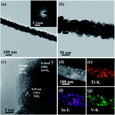
To further confirm the microscopic morphologies and crystal structures of the TiO2/InVO4 NFs, TEM images are recorded in Fig. 2. It is obvious that the TiO2/InVO4 NFs with a diameter of ∼100 nm (Fig. 2(a)) are composed of many distinct crystal particles and flakes, as displayed in Fig. 2(b). Then, we obtained an HRTEM image of the TiO2/InVO4 NFs to further observe the distributional crystal particles, and the result is presented in Fig. 2(c). The lattice distance of 0.35 nm is attributed to the (101) lattice distance of anatase TiO2, and the measured lattice fringes of 0.28 nm and 0.36 nm correspond to the interplanar spacings of the (200) and (021) planes of orthorhombic InVO4, respectively, indicating that the TiO2/InVO4 nanoheterostructures have been prepared successfully. Additionally, the results of the STEM-EDS elemental mapping analysis are displayed in Fig. 2(d–g) to further explore the element distributions in the TiO2/InVO4 nanofibers. It is obvious that the TiO2/InVO4 nanofibers are mainly composed of the metals Ti, In, and V, and the diameters of In and V are larger than that of Ti, which indicates that the flake-structure on the surfaces of the TiO2/InVO4 NFs can be assigned to the secondary growth of InVO4.
In order to further determine the molar ratio of elements in all the TiO2/InVO4 NFs (Ti/In = 4![[thin space (1/6-em)]](https://www.rsc.org/images/entities/char_2009.gif) :
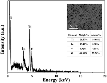
:![[thin space (1/6-em)]](https://www.rsc.org/images/entities/char_2009.gif) 1), energy dispersive spectroscopic (EDS) analysis was applied and the results are shown in Fig. 3, in which it can be observed that Ti, In, V, and O appear in the TiO2/InVO4 NFs, and the atomic ratios of Ti, In, and V are 14.08%, 3.38%, and 4.98%, respectively, implying the molar ratio of Ti/In is about 4.2, which is in agreement with the set value of the Ti/In molar ratio in the electrospinning process. Furthermore, XPS measurements were employed and the results are displayed in Fig. 4. Fig. 4(a) shows the holistic survey spectrum of the TiO2/InVO4 NFs, in which Ti, In, V, and O are detected. In addition, the Ti 2p, In 3d, and V 2p core-level spectra of the TiO2/InVO4 NFs are shown in Fig. 4(b–d). The peaks at 444.5 eV and 452.0 eV in the In 3d core-level spectrum, as shown in Fig. 3(b), correspond to In 3d3/2 and In 3d5/2 for In3+ species, respectively.31 As shown in Fig. 4(c), the V 2p peaks are located at 517.1 eV and 524.6 eV, which can be ascribed to V5+.32 From the Ti 2p core-level spectrum in Fig. 4(d), two clearly evident peaks centered at 463.8 and 458.2 eV can be assigned to Ti 2p1/2 and Ti 2p3/2, respectively, which belong to the Ti4+ elemental chemical state of TiO2.33 It can be therefore concluded that the TiO2/InVO4 NFs have been fabricated successfully.
1), energy dispersive spectroscopic (EDS) analysis was applied and the results are shown in Fig. 3, in which it can be observed that Ti, In, V, and O appear in the TiO2/InVO4 NFs, and the atomic ratios of Ti, In, and V are 14.08%, 3.38%, and 4.98%, respectively, implying the molar ratio of Ti/In is about 4.2, which is in agreement with the set value of the Ti/In molar ratio in the electrospinning process. Furthermore, XPS measurements were employed and the results are displayed in Fig. 4. Fig. 4(a) shows the holistic survey spectrum of the TiO2/InVO4 NFs, in which Ti, In, V, and O are detected. In addition, the Ti 2p, In 3d, and V 2p core-level spectra of the TiO2/InVO4 NFs are shown in Fig. 4(b–d). The peaks at 444.5 eV and 452.0 eV in the In 3d core-level spectrum, as shown in Fig. 3(b), correspond to In 3d3/2 and In 3d5/2 for In3+ species, respectively.31 As shown in Fig. 4(c), the V 2p peaks are located at 517.1 eV and 524.6 eV, which can be ascribed to V5+.32 From the Ti 2p core-level spectrum in Fig. 4(d), two clearly evident peaks centered at 463.8 and 458.2 eV can be assigned to Ti 2p1/2 and Ti 2p3/2, respectively, which belong to the Ti4+ elemental chemical state of TiO2.33 It can be therefore concluded that the TiO2/InVO4 NFs have been fabricated successfully.
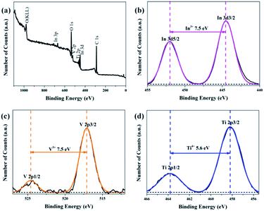 | ||
Fig. 4 (a) XPS survey spectrum of the TiO2/InVO4 NFs (Ti/In = 4![[thin space (1/6-em)]](https://www.rsc.org/images/entities/char_2009.gif) : :![[thin space (1/6-em)]](https://www.rsc.org/images/entities/char_2009.gif) 1), and (b–d) high resolution XPS spectra of the In 3d, V 2p, and Ti 2p core-level binding energies, respectively. 1), and (b–d) high resolution XPS spectra of the In 3d, V 2p, and Ti 2p core-level binding energies, respectively. | ||
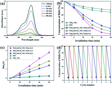
We then investigated the photocatalytic performance of TiO2 NFs and TiO2/InVO4 NFs with different Ti/In molar ratios toward the photodegradation process of RhB solution. As shown in Fig. 5(a), after adding 50 mg TiO2/InVO4 NFs (Ti/In = 4![[thin space (1/6-em)]](https://www.rsc.org/images/entities/char_2009.gif) :
:![[thin space (1/6-em)]](https://www.rsc.org/images/entities/char_2009.gif) 1) as a photocatalyst into RhB solution, the λmax intensity of the absorption spectral changes of the RhB solution is significantly decreased with irradiation time. Fig. 5(b) presents the corresponding concentration change in the RhB solution when using different samples as photocatalysts under visible-light irradiation. It is obviously that after 80 min of visible-light irradiation, only 18% and 32% of RhB molecules are decomposed by the TiO2 NFs and standard P25, respectively, which can be assigned to their poor visible-light absorption and short photogenerated charge lifetime. As for the TiO2/InVO4 NFs, at least 80% of RhB molecules are effectively decomposed, indicating that the TiO2/InVO4 NFs achieve an outstanding enhanced visible photocatalytic performance, better than that of pure TiO2 NFs. Moreover, while using the TiO2/InVO4 NFs with a Ti/In molar ratio of 4
1) as a photocatalyst into RhB solution, the λmax intensity of the absorption spectral changes of the RhB solution is significantly decreased with irradiation time. Fig. 5(b) presents the corresponding concentration change in the RhB solution when using different samples as photocatalysts under visible-light irradiation. It is obviously that after 80 min of visible-light irradiation, only 18% and 32% of RhB molecules are decomposed by the TiO2 NFs and standard P25, respectively, which can be assigned to their poor visible-light absorption and short photogenerated charge lifetime. As for the TiO2/InVO4 NFs, at least 80% of RhB molecules are effectively decomposed, indicating that the TiO2/InVO4 NFs achieve an outstanding enhanced visible photocatalytic performance, better than that of pure TiO2 NFs. Moreover, while using the TiO2/InVO4 NFs with a Ti/In molar ratio of 4![[thin space (1/6-em)]](https://www.rsc.org/images/entities/char_2009.gif) :
:![[thin space (1/6-em)]](https://www.rsc.org/images/entities/char_2009.gif) 1 as photocatalysts, about 95% of RhB molecules are decomposed. In addition, as shown in Fig. 5(c), the degradation rates obtained over the TiO2/InVO4 NFs (Ti/In = 4
1 as photocatalysts, about 95% of RhB molecules are decomposed. In addition, as shown in Fig. 5(c), the degradation rates obtained over the TiO2/InVO4 NFs (Ti/In = 4![[thin space (1/6-em)]](https://www.rsc.org/images/entities/char_2009.gif) :
:![[thin space (1/6-em)]](https://www.rsc.org/images/entities/char_2009.gif) 1), TiO2/InVO4 NFs (Ti/In = 2
1), TiO2/InVO4 NFs (Ti/In = 2![[thin space (1/6-em)]](https://www.rsc.org/images/entities/char_2009.gif) :
:![[thin space (1/6-em)]](https://www.rsc.org/images/entities/char_2009.gif) 1), TiO2/InVO4 NFs (Ti/In = 8
1), TiO2/InVO4 NFs (Ti/In = 8![[thin space (1/6-em)]](https://www.rsc.org/images/entities/char_2009.gif) :
:![[thin space (1/6-em)]](https://www.rsc.org/images/entities/char_2009.gif) 1), P25, and TiO2 NFs are 0.03632, 0.0238, 0.01756, 0.0033, and 0.00244, respectively. Furthermore, the photocatalytic performance of TiO2/InVO4 NFs was enhanced with the increasing amount of InVO4 and reached the best photocatalytic activity at a Ti/In molar ratio of 4
1), P25, and TiO2 NFs are 0.03632, 0.0238, 0.01756, 0.0033, and 0.00244, respectively. Furthermore, the photocatalytic performance of TiO2/InVO4 NFs was enhanced with the increasing amount of InVO4 and reached the best photocatalytic activity at a Ti/In molar ratio of 4![[thin space (1/6-em)]](https://www.rsc.org/images/entities/char_2009.gif) :
:![[thin space (1/6-em)]](https://www.rsc.org/images/entities/char_2009.gif) 1. The increasing surface area with the increase in the amount of InVO4 is beneficial for the improvement of the photocatalytic activity, which is in agreement with the morphology results and dark absorption during the photocatalysis process. However, with a further increase of InVO4 amount, the epitaxial growth of InVO4 would undermine the uniformity of the nanoheterostructures and suppress the separation of the electron–hole pairs, so superabundant InVO4 is conversely unfavorable for improving photocatalytic activity. So, the TiO2/InVO4 NFs with a Ti/In molar ratio of 4
1. The increasing surface area with the increase in the amount of InVO4 is beneficial for the improvement of the photocatalytic activity, which is in agreement with the morphology results and dark absorption during the photocatalysis process. However, with a further increase of InVO4 amount, the epitaxial growth of InVO4 would undermine the uniformity of the nanoheterostructures and suppress the separation of the electron–hole pairs, so superabundant InVO4 is conversely unfavorable for improving photocatalytic activity. So, the TiO2/InVO4 NFs with a Ti/In molar ratio of 4![[thin space (1/6-em)]](https://www.rsc.org/images/entities/char_2009.gif) :
:![[thin space (1/6-em)]](https://www.rsc.org/images/entities/char_2009.gif) 1 may exhibit outstanding synergistic effects with an appropriate surface area and nanoheterostructure, thereby allowing them to displaying the highest photocatalytic activity. Hence, we mainly conducted in-depth causal discussions on the enhanced visible-light photocatalytic performance of TiO2/InVO4 NFs with a Ti/In molar ratio of 4
1 may exhibit outstanding synergistic effects with an appropriate surface area and nanoheterostructure, thereby allowing them to displaying the highest photocatalytic activity. Hence, we mainly conducted in-depth causal discussions on the enhanced visible-light photocatalytic performance of TiO2/InVO4 NFs with a Ti/In molar ratio of 4![[thin space (1/6-em)]](https://www.rsc.org/images/entities/char_2009.gif) :
:![[thin space (1/6-em)]](https://www.rsc.org/images/entities/char_2009.gif) 1 in the following research. Based on further practical application, the stability of the photocatalyst is a very significant factor for recycling. Herein, ten cycles of the photodegradation behaviour of RhB are shown in Fig. 5(d) in order to evaluate the photocatalytic stability of the TiO2/InVO4 NFs. After each cycle of the photocatalysis reaction process, it can seen that there is only negligible reduction in the photocatalytic activity, indicating the excellent reusability and stability of the TiO2/InVO4 NFs. In a word, TiO2/InVO4 NFs exert an outstanding stability, and a much enhanced visible-light photocatalytic activity compared with pure TiO2 NFs.
1 in the following research. Based on further practical application, the stability of the photocatalyst is a very significant factor for recycling. Herein, ten cycles of the photodegradation behaviour of RhB are shown in Fig. 5(d) in order to evaluate the photocatalytic stability of the TiO2/InVO4 NFs. After each cycle of the photocatalysis reaction process, it can seen that there is only negligible reduction in the photocatalytic activity, indicating the excellent reusability and stability of the TiO2/InVO4 NFs. In a word, TiO2/InVO4 NFs exert an outstanding stability, and a much enhanced visible-light photocatalytic activity compared with pure TiO2 NFs.
Based on the excellent results, we have mainly conducted in-depth causal discussions on three aspects of the enhanced visible-light photocatalytic performance of the TiO2/InVO4 NFs. Firstly, it is well known that surface area is an important factor for photocatalysis.34 Hence, as shown in Fig. 6(a), we employed a BET adsorption/desorption of nitrogen gas method to evaluate the specific surface area of the TiO2 NFs and TiO2/InVO4 NFs. The BET surface area of the TiO2/InVO4 NFs, calculated from the nitrogen isotherm curve, is 30.5 m2 g−1, which is about two times higher than that of the TiO2 NFs (16.8 m2 g−1). Obviously, the increased surface area of the TiO2/InVO4 NFs would provide a larger available active area for the photocatalytic reaction. Accordingly, the increasing surface area of the TiO2/InVO4 NFs would efficiently promote photocatalytic activity.
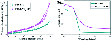 | ||
| Fig. 6 (a) N2 adsorption–desorption isotherms and (b) UV-Vis absorbance spectra of the TiO2 NFs and TiO2/InVO4 NFs. | ||
In particular, optical absorption characteristics have a direct influence on the photocatalytic activity of semiconductors. Herein, we employed UV-Vis absorbance spectroscopy to attest whether TiO2/InVO4 NFs have a wider light absorption range for visible light compared with TiO2 NFs, and the results are shown in Fig. 6(b). TiO2 NFs present an evident absorption edge located at 400 nm, derived from the intrinsic energy gap of TiO2. The UV-Vis spectra of the TiO2/InVO4 NFs reveal a wide visible-light absorption band around 400–650 nm, which contributed to the introduction of the narrow band gap InVO4 semiconductor. This effectual change of the absorption spectra indicates that the TiO2/InVO4 NFs have broader spectral harvesting, ultimately leading to the improvement of the visible-light photocatalytic activity.
It is fairly well acknowledged that a lower PL emission intensity of the samples under the same laser irradiation intensity implies less electron–hole recombination.35 Herein, we employed steady-state and time-resolved transient PL spectroscopy to characterize the capability of electron–hole pair separation in the nanofibers. As shown in Fig. 7(a), in the TiO2 NF PL spectrum, the strong emission band at around 550–850 nm is mainly attributed to deep and shallow trap centers of oxygen defects and excitons.36 However, the TiO2/InVO4 NFs have a substantially lower PL intensity than the TiO2 NFs, which implies that recombination of the photogenerated electron–hole pairs in the TiO2/InVO4 NFs is effectively suppressed.
Time-resolved photoluminescence (TRPL) is an effective method employed to extract the carrier lifetime (τ), which can directly indicate various radiative and non-radiative loss channels responsible for photogenerated carrier recombination.37 To further verify the nanoheterojunction’s functions of electron–hole separation and carrier transfer in the TiO2/InVO4 NFs, TRPL was employed at room temperature to explore the dynamics of the photogenerated charge. The transient emission spectra for the TiO2 NFs and TiO2/InVO4 NFs are shown in Fig. 7(b and c). The PL decay profile is fitted using a multiexponential function as follows:38,39
 | (1) |
 | (2) |
The values for the average time calculated based on two-exponential decays for the TiO2/InVO4 NFs and TiO2 NFs are 22 ns and 15 ns, respectively. In order to compare the separation efficiency of the TiO2/InVO4 heterostructures, we list the carrier lifetimes of different TiO2-based heterostructures reported previously in Table 1, and it is obvious that the TiO2/InVO4 NFs with tailored heterostructure features exhibit longer carrier lifetimes than TiO2/SiO2, TiO2/In2S3, and TiO2/MoS2, implying that this kind of heterostructure prepared by electrospinning can provide ample heterojunction interfaces for more separation channels for photogenerated electron–hole pairs.
To better understand the charge separation in TiO2/InVO4 NFs, a schematic illustration of the efficient separation and transport of photogenerated charge in the TiO2/InVO4 NFs is represented in Fig. 7(d). The standard literature energy levels of TiO2 and InVO4 (conduction bands of −4.0 eV and −3.6 eV, valance bands of −7.0 eV and −5.7 eV, and Fermi levels of −4.2 eV and −4.5 eV, vs. the vacuum level, respectively) were employed for the energy band matching analysis here.45 The matching energy band between InVO4 and TiO2 is shown in Fig. 6(d), when the nanoheterostructures are formed, the Fermi energy bands of TiO2 and InVO4 are at the same level, which thus leads both the conduction band (EC) and valence band (EV) of InVO4 to locate above those of TiO2. Under visible-light irradiation, InVO4 in the TiO2/InVO4 NFs is photoexcited to produce electron–hole pairs, and owing to the incomparable nanoheterojunction structure formed at the interfaces of TiO2 and InVO4, the photogenerated electrons can facilely transport to the EC of TiO2. Hereby, numerous photogenerated electrons transport from the EC of InVO4 to that of TiO2, and photogenerated holes concentrate on the EV of InVO4. In this way, the separation of the photogenerated charge can be efficiently facilitated, thereby prolonging the carrier lifetimes and resulting in the enhanced photocatalytic activity of the TiO2/InVO4 NFs under visible-light irradiation.
4. Conclusions
In summary, TiO2/InVO4 NFs were successfully fabricated by a facile one-pot electrospinning method. The TiO2/InVO4 NFs showed a significantly enhanced photocatalytic performance; almost 95% of RhB molecules were decomposed within 80 min by the TiO2/InVO4 NFs (Ti/In = 4![[thin space (1/6-em)]](https://www.rsc.org/images/entities/char_2009.gif) :
:![[thin space (1/6-em)]](https://www.rsc.org/images/entities/char_2009.gif) 1), but only 18% of RhB molecules were decomposed by pure TiO2 NFs. Moreover, the time-resolved transient PL spectra reveal that the TiO2/InVO4 NFs exhibit a prolonged average carrier lifetime of 22 ns, more than that of the TiO2 NFs, which can promote photogenerated carrier separation. Accordingly, the resulting TiO2/InVO4 NFs display excellent visible-light photocatalytic performance, owing to their prominent visible-light harvesting and electron–hole separation properties. It is indisputable that TiO2/InVO4 NFs may shed new light on highly efficient visible-light nanoheterostructured photocatalysts with longer carrier lifetimes.
1), but only 18% of RhB molecules were decomposed by pure TiO2 NFs. Moreover, the time-resolved transient PL spectra reveal that the TiO2/InVO4 NFs exhibit a prolonged average carrier lifetime of 22 ns, more than that of the TiO2 NFs, which can promote photogenerated carrier separation. Accordingly, the resulting TiO2/InVO4 NFs display excellent visible-light photocatalytic performance, owing to their prominent visible-light harvesting and electron–hole separation properties. It is indisputable that TiO2/InVO4 NFs may shed new light on highly efficient visible-light nanoheterostructured photocatalysts with longer carrier lifetimes.
Conflicts of interest
There are no conflicts to declare.Acknowledgements
This work was supported by the National Natural Science Foundation of China (No. 11704354) and the Hunan Provincial Innovation Foundation for Postgraduate (No. 8443|431000203431000203).Notes and references
- D. M. Schultz and T. P. Yoon, Science, 2014, 343, 1239176 CrossRef PubMed.
- K. Nakata, B. Liu, Y. Goto, T. Ochiai, M. Sakai, H. Sakai, T. Murakami, M. Abe and A. Fujishima, Chem. Lett., 2011, 40, 1161–1162 CrossRef.
- J. Ran, J. Zhang, J. Yu, M. Jaroniec and S. Z. Qiao, Chem. Soc. Rev., 2014, 43, 7787–7812 RSC.
- A. Fujishima and K. Honda, Nature, 1972, 238, 37 CrossRef PubMed.
- Y. Bai, I. Mora-Sero, F. D. Angelis, J. Bisquert and P. Wang, Chem. Rev., 2014, 114, 10095–10130 CrossRef PubMed.
- S. G. Kumar and L. G. Devi, J. Phys. Chem. A, 2011, 115, 13211–13241 CrossRef PubMed.
- C. P. Sajan, S. Wageh, A. A. Al-Ghamdi, J. Yu and S. Cao, Nano Res., 2016, 9, 3–27 CrossRef.
- J. Hensel, G. Wang, Y. Li and J. Z. Zhang, Nano Lett., 2010, 10, 478–483 CrossRef PubMed.
- R. Asahi, T. Morikawa, T. Ohwaki, K. Aoki and Y. Taga, Science, 2001, 293, 269–271 CrossRef PubMed.
- T. Huang, S. Mao, J. Yu, Z. Wen, G. Lu and J. Chen, RSC Adv., 2013, 3, 16657–16664 RSC.
- W. He, Z. Fang, K. Zhang, X. Li, D. Ji, X. Jiang, C. Qiu and K. Guo, RSC Adv., 2015, 5, 54853–54860 RSC.
- X. Chen, L. Liu, Y. Y. Peter and S. S. Mao, Science, 2011, 331, 746–750 CrossRef PubMed.
- Y. Shi, D. Yang, Y. Li, J. Qu and Z. Z. Yu, Appl. Surf. Sci., 2017, 426, 622–629 CrossRef.
- X. Zhang, Z. Shen, C. Cheng, L. Shi, R. Cheng and J. Dong, RSC Adv., 2017, 7, 52172–52179 RSC.
- C. Cheng, J. Shi, Y. Hu and L. Guo, Nanotechnology, 2017, 28, 164002 CrossRef PubMed.
- H. Zhang, F. Liu, H. Wu, X. Cao, J. Sun and W. Lei, RSC Adv., 2017, 7, 40327–40333 RSC.
- M. N. Ha, F. Zhu, Z. Liu, L. Wang, L. Liu, G. Lu and Z. Zhao, RSC Adv., 2016, 6, 21111–21118 RSC.
- H. Wang, L. Zhang, Z. Chen, J. Hu, S. Li, Z. Wang, J. Liu and X. Wang, Chem. Soc. Rev., 2014, 43, 5234–5244 RSC.
- C. Cheng, W. Ren and H. Zhang, Nano Energy, 2014, 5, 132–138 CrossRef.
- P. G. Ramos, E. Flores, L. A. Sánchez, R. J. Candal, M. Hojamberdiev, W. Estrada and J. Rodriguez, Appl. Surf. Sci., 2017, 426, 844–851 CrossRef.
- F. Tian, D. Hou, F. Hu, K. Xie, X. Qiao and D. Li, Appl. Surf. Sci., 2017, 391(Part B), 295–302 CrossRef.
- X. Ren, X. Qi, Y. Shen, S. Xiao, G. Xu, Z. Zhang, Z. Huang and J. Zhong, J. Phys. D: Appl. Phys., 2016, 49, 315304 CrossRef.
- S. P. Adhikari, G. P. Awasthi, J. Lee, C. H. Park and C. S. Kim, RSC Adv., 2016, 6, 55079–55091 RSC.
- F. Xu, J. Zhang, B. Zhu, J. Yu and J. Xu, Appl. Catal., B, 2018, 230, 194–202 CrossRef.
- X. Zhang, Catal. Lett., 2014, 144, 1253–1257 CrossRef.
- Y. Yan, X. Liu, W. Fan, P. Lv and W. Shi, Chem. Eng. J., 2012, 200–202, 310–316 CrossRef.
- J. Shen, H. Yang, Y. Feng, Q. Cai and Q. Shen, Solid State Sci., 2014, 32, 8–12 CrossRef.
- I. A. Perales-Martínez, V. Rodríguez-González, S. W. Lee and S. Obregón, J. Photochem. Photobiol., A, 2015, 299, 152–158 CrossRef.
- Y. Min, K. Zhang, Y. C. Chen and Y. G. Zhang, Ultrason. Sonochem., 2012, 19, 883–889 CrossRef PubMed.
- L. Ge, M. Xu and H. Fang, Mater. Lett., 2007, 61, 63–66 CrossRef.
- F. Guo, W. Shi, X. Lin, X. Yan, Y. Guo and G. Che, Sep. Purif. Technol., 2015, 141, 246–255 CrossRef.
- A. Chakrabarti, K. Hermann, R. Druzinic, M. Witko, F. Wagner and M. Petersen, Phys. Rev. B: Condens. Matter Mater. Phys., 1999, 59, 10583–10590 CrossRef.
- H. Li, Y. Wang, G. Chen, Y. Sang, H. Jiang, J. He, X. Li and H. Liu, Nanoscale, 2016, 8, 6101–6109 RSC.
- G. Tian, Y. Chen, W. Zhou, K. Pan, C. Tian, X. Huang and H. Fu, CrystEngComm, 2011, 13, 2994 RSC.
- Z. Zhang, C. Shao, X. Li, L. Zhang, H. Xue, C. Wang and Y. Liu, J. Phys. Chem. C, 2010, 114, 7920–7925 CrossRef.
- K. Iijima, M. Goto, S. Enomoto, H. Kunugita, K. Ema, M. Tsukamoto, N. Ichikawa and H. Sakama, J. Lumin., 2008, 128, 911–913 CrossRef.
- H. H. Wang, Q. Chen, H. Zhou, L. Song, Z. S. Louis, N. D. Marco, Y. Fang, P. Sun, T. B. Song, H. Chen and Y. Yang, J. Mater. Chem. A, 2015, 3, 9108–9115 RSC.
- J. L. Wu, F. C. Chen, Y. S. Hsiao, F. C. Chien, P. L. Chen, C. H. Kuo, M. H. Huang and C. S. Hsu, ACS Nano, 2011, 5, 959–967 CrossRef PubMed.
- S. W. Cao, X. F. Liu, Y. P. Yuan, Z. Y. Zhang, Y. S. Liao, J. Fang, S. C. J. Loo, T. C. Sum and C. Xue, Appl. Catal., B, 2014, 147, 940–946 CrossRef.
- Y. Li, T. Li, J. Tian, X. Wang and H. Cui, Part. Part. Syst. Charact., 2017, 34, 1700127 CrossRef.
- X. Zeng and W. Qin, Mater. Lett., 2016, 182, 347 CrossRef.
- B. R. Masters, J. Biomed. Opt., 2008, 13, 029901 CrossRef.
- K. Miyashita, S. Kuroda, S. Tajima, K. Takehira, S. Tobita and H. Kubota, Chem. Phys. Lett., 2003, 369, 225–231 CrossRef.
- H. S. Han, K. M. Kim, C. W. Lee, C. S. Lee, R. C. Pawar, J. L. Jones, Y. R. Hong, J. H. Ryu, T. Song, S. H. Kang, H. Choi and S. Mhin, Phys. Chem. Chem. Phys., 2017, 19, 28207–28215 RSC.
- G. Xiao, X. Wang, D. Li and X. Fu, J. Photochem. Photobiol., A, 2008, 193, 213–221 CrossRef.
| This journal is © The Royal Society of Chemistry 2018 |

