 Open Access Article
New generation of spinning systems for robust active mixing on microfluidic CDs: oil/water emulsion as an evaluation test
Ala'aldeen Al-Halhouli *a,
Ghaith Al-Shishania,
Ahmed Albagdadya and
Wisam Al-Faqheriab
aNanoLab, School of Applied Technical Sciences, German Jordanian University, Amman, Jordan. E-mail: alaaldeen.alhalhouli@gju.edu.jo
bMicroNano Mechatronic Lab, University of Windsor, Mechanical, Automotive & Materials Engineering, Windsor, ON, Canada
First published on 26th July 2018
Abstract
Microfluidic CDs (or Lab-on-Disc) continue to emerge in various applications of real life sciences, including biomedical and pharmaceutical fields. However, microfluidic CDs with advanced and efficient unit operation tools, such as pumping, valving, and mixing, need to be implemented to achieve the required applications in these fields. In this work, a novel generation of a spinning system to perform robust active mixing is developed for microfluidic CDs. The developed system is equipped with a dual-motor and dual-CD configuration to perform magnetically driven active mixing. The results show that the developed spinning system can provide a wide range of mixing frequencies independent of the spinning speed of the microfluidic CD. To evaluate the performance of this system under extreme conditions, an emulsion process of oil and water was conducted. Although the oil produced high drag force on the mixing magnet, the emulsion process successfully reached a steady state of mixing within a few seconds (approximately 3.5 s), and the mixture became homogeneous at 75 seconds. To demonstrate one of the potential applications of the proposed developed spinning setup, microparticles were successfully extracted from water to oil using water/oil emulsion on the microfluidic CD. In conclusion, mixing can be performed without influencing the integrated microfluidic components such as valves or pumps. This improvement can widen the range of applicability of microfluidic CDs in multi-step and complex processes where mixing is essential.
Introduction
Since the introduction of the Miniaturized Systems for Chemistry and Life Sciences, μTAS, much research has been directed towards the miniaturization of commercial conventional diagnostic systems to be portable, affordable, and applicable in extreme point of care regions.1 This includes the miniaturization of biological and chemical processes on one of the main two microfluidic platforms: Lab-on-Chip (LOC, a stationary chip with microchannels and chambers) and Lab-on-Disc (LOD, a spinning platform in the shape of a compact disc), or microfluidic CD.1,2 Microfluidic CDs draw more attention of researchers in the biological fields due to their various advantages, such as independence of the sample properties to the centrifugal force, total isolation between the platform and pumping unit to prevent contamination, and low setup complexity.2For the microfluidic CD to be successfully implemented in total analysis processes, it needs to be supported with a wide range of unit operation. According to Strohmeier and Keller,3 unit operation is defined as the basic functionalities of the microfluidic platform, e.g., sample storage and supply, pumping, valving, metering, and mixing. Sample mixing, or homogenization, is an essential step in most biological and chemical processes.1,3–6 However, mixing on a microfluidic CD is a challenging task due to the high artificial gravity generated by centrifugal force, which is ideal for separation but not mixing.3,7 Moreover, pure passive diffusion mixing is insufficient due to the low sample volume, which ranges from hundreds of nanoliters to a few microliters.3
For the last few decades, a wide range of passive and active mixing methods were proposed for microfluidic CD platforms. Passive mixing can be defined as the stirring of different liquids by special geometry of the microchannel or chamber,6,8–10 implementation of inertial and/or Coriolis forces,11,12 shake-wise mixing,5 reciprocating flow-based mixing,13 or the integration of a deformable microballoon layer.14 All the proposed passive methods were conducted without the need for an external force or trigger. On the other hand, active mixing is performed by implementing an external force or trigger during the spinning of the microfluidic CD, such as the implementation of magnetic beads in the mixing chamber, which are diffused by external permanent magnets5 or pneumatic mixing.15
The implantation of external permanent magnets to deflect/shake magnetic beads/discs on the microfluidic CD was implemented in various studies to produce efficient mixing,5 pumping/valving,16 and cell lysis.17 The method is mainly based on preloading the mixing/cell lysis chamber with magnetic discs or magnetic beads and fixing multiple permanent magnets in a radially shifted position under the microfluidic CD. When the CD is spun, the preloaded magnets are periodically diverted under the effect of the fixed permanent magnets. This method can produce robust and fast mixing compared to other passive and active methods. However, the quality and period of mixing are always controlled by the spinning speed of the microfluidic CD, i.e., faster spinning leads to better and faster mixing due to the higher reflection frequency of preloaded magnets. However, the main disadvantage of this method is that spinning the microfluidic CD at a high frequency can lead to premature liquid bursting of the passive valves or failure of other integrated processes that require lower spinning speeds.
Therefore, a novel dual-motor spinning system for microfluidic CDs is reported in this paper for the first time. The developed system mainly consists of two independently controlled DC motors to spin two coaxial spinning CDs: a primary CD (microfluidic CD) and a secondary CD (magnetic CD). Both CDs can be spun at various spinning speeds in the same or opposite direction to produce a range of fluctuation frequencies of the preloaded magnetic rings. With the newly developed generation of the spinning system, active robust mixing can be performed at a low range of spinning speeds (even at 0 rpm) by adjusting the speed of the secondary magnetic CD.
Principle of operation
Microfluidic compact discs (CDs) are circular-shaped microfluidic platforms with an integrated network of microchannels and chambers that are designed to perform a specific process (Fig. 1(a)). In contrast to microfluidic chips, microfluidic CDs rely on centrifugation to pump and control liquids across the different channels and chambers on the platform. In most cases, a custom-made spin stand (or spinning system) is used to spin the platform and the progress is recorded with a high-speed camera. While spinning the platform, centrifugal and capillary forces act on the preloaded liquid in two opposite directions: the centrifugal force is directed radially towards the outer edge of the CD, while the capillary force is directed towards the platform centre (Fig. 1(a)). The centrifugal force per unit volume and the produced pressure on the liquid can be calculated as follows:7
Fcen = ρω2![[r with combining macron]](https://www.rsc.org/images/entities/i_char_0072_0304.gif)
| (1) |
Pcen = ρω2Δr![[r with combining macron]](https://www.rsc.org/images/entities/i_char_0072_0304.gif)
| (2) |
![[r with combining macron]](https://www.rsc.org/images/entities/i_char_0072_0304.gif) is the distance of the loaded liquid column center from the microfluidic CD center. In multi-step designs with multiple channels and chambers, as liquid moves forward in a microfluidic channel due to the centrifugal force, the capillary force acts against this liquid movement (Fig. 1(a)). Capillary pressure on a microfluidic CD can be calculated using the following expression:2,7
is the distance of the loaded liquid column center from the microfluidic CD center. In multi-step designs with multiple channels and chambers, as liquid moves forward in a microfluidic channel due to the centrifugal force, the capillary force acts against this liquid movement (Fig. 1(a)). Capillary pressure on a microfluidic CD can be calculated using the following expression:2,7
 | (3) |
 | (4) |
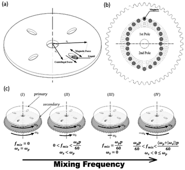 | ||
| Fig. 1 Microfluidic CD platform (a) primary microfluidic CD with main forces acting on the mixing chamber (b) secondary CD with the fixed magnets and 2-pole setup (c) operational mode. | ||
In this paper, a novel dual-motor spinning system for an active mixing mechanism is proposed. Fig. 1(a) and (b) present the two implemented CDs with the microfluidic CD (primary CD) on top and the magnetic CD (secondary CD) at the bottom. A free moving magnetic ring is preloaded inside the microfluidic mixing chamber, and twenty-four permanent magnets are fixed in a predefined radially shifted position on the secondary CD (Fig. 1(b)). When the two CDs spin at different speeds, the relative speed of one CD to the other forces the magnetic ring to oscillate at a specific frequency, i.e., the mixing frequency (fmix). For our system, a mixing magnetic ring travelling from the mixing chamber's inner wall (wall closer to the CD center) towards the outer wall (wall closer to CD outer edge) and then returning to the initial position is considered to have completed a full cycle. This journey of the magnetic ring between the inner and outer wall is segmented into intermediate steps based on the fixed magnet distribution on the secondary CD. This is to ensure successful magnet translation by reducing the distance travelled between steps, in turn increasing the magnetic pull force. The mixing frequency at any speed of the primary and secondary CD is described by the following equation:
 | (5) |
The total force (Ftotal) acting on the magnet ring can be calculated as:
![[F with combining right harpoon above (vector)]](https://www.rsc.org/images/entities/i_char_0046_20d1.gif) total = total = ![[F with combining right harpoon above (vector)]](https://www.rsc.org/images/entities/i_char_0046_20d1.gif) cen + cen + ![[F with combining right harpoon above (vector)]](https://www.rsc.org/images/entities/i_char_0046_20d1.gif) mag + mag + ![[F with combining right harpoon above (vector)]](https://www.rsc.org/images/entities/i_char_0046_20d1.gif) stokes stokes
| (6) |
![[F with combining right harpoon above (vector)]](https://www.rsc.org/images/entities/i_char_0046_20d1.gif) mag is the pulling force between the moving magnet and the magnets on the secondary CD, and
mag is the pulling force between the moving magnet and the magnets on the secondary CD, and ![[F with combining right harpoon above (vector)]](https://www.rsc.org/images/entities/i_char_0046_20d1.gif) stokes is the Stokes drag force due to the liquids to be mixed. Depending on the travel direction of the mixing ring (toward the center or towards the outer edge of the CD), the Fcen can act against or with the Fmag. Eqn (6) can be implemented to calculate the operation limits of the mixing system that are mainly affected by the spinning speed of the primary CD, the magnetic force between magnets and the drag force of the mixed liquids.
stokes is the Stokes drag force due to the liquids to be mixed. Depending on the travel direction of the mixing ring (toward the center or towards the outer edge of the CD), the Fcen can act against or with the Fmag. Eqn (6) can be implemented to calculate the operation limits of the mixing system that are mainly affected by the spinning speed of the primary CD, the magnetic force between magnets and the drag force of the mixed liquids.
To produce a wide range of mixing frequencies, the proposed system can work in four operational modes, as shown in Fig. 1(b). For any constant primary CD speed, the four modes are defined based on the relative speed of the secondary CD to the primary CD as follows: (i) the primary and secondary CDs spin at the same speed and direction resulting in no mixing (0 Hz mixing frequency) (ii) the secondary CD spins slower than the primary CD and in the same direction to produce relatively low mixing frequencies (iii) the secondary CD is stationary, and the mixing frequency is solely dependent on the primary CD speed and number of poles and (iv) the secondary CD spins in the direction opposite to the primary CD to achieve relatively high mixing frequencies. With these operational modes, the user can define parameters for the best mixing output.
Experimental setup
In this work, a novel spinning system for the microfluidic CD was designed and developed in the lab. The spinning system was built with a stainless-steel structure for a rigid setup with low vibration effect. The spinning system is equipped with two identical brushed DC motors that are separately controlled: the primary motor and secondary motor (Fig. 2). The primary motor is directly attached to the setup table, while the secondary motor is inversely (upside down) attached on top of the table using a special holder. A custom-made gear is attached to the secondary motor to spin the secondary CD. Additionally, a custom-made threaded shaft is attached to the primary motor to hold the primary and secondary CDs. The motion of the secondary CD is separated from the motion of the shaft using a ball bearing.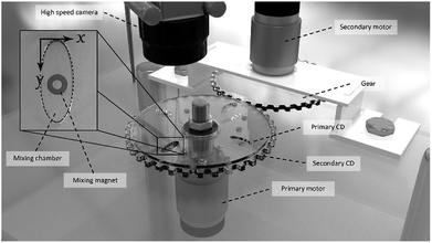 | ||
| Fig. 2 Spinning system setup showing the two integrated DC motors and the configuration of the primary CD, secondary CD, high-speed camera, mixing chamber, and mixing magnet. | ||
The spinning setup is equipped with a high-speed camera (Basler, Ahrensburg, Germany) that is synchronized with the spinning motor to capture one frame per CD revolution. The system is also equipped with a custom-made LED lighting system. The lighting system offers two operation modes: dimming mode (brightness is controlled by a potentiometer) and stroboscope mode (LEDs blink according to CD speed). NI Labview was used to build the user-interface for the developed spinning setup. The developed software provides real-time control and feedback for the motor's speed, direction, and automatic frame rate adjustment. The frame rate of the camera is calculated relative to the speed of the motor such that the camera captures a single frame per revolution to ensure that the microfluidic channel on the rotating disk is captured at the same location in all captured frames.
A three-layers microfluidic CD with four oval-shaped mixing chambers was fabricated to test and demonstrate the efficiency of the proposed mixing mechanism. The CD consists of three poly(methyl methacrylate) (PMMA) layers (Moden Glas, Bangkok, Thailand) bonded together with two adhesive layers. The current microfluidic CDs are fabricated with 120 mm in diameter to replicate the diameter of commercial digital CDs. However, microfluidic CDs can be easily scaled up to accommodate more microfluidic features. In addition, this dimensional adjustment should be within the endorsement range of the spinning motors and stand. The mixing chambers were cut into the 3 mm thick middle PMMA layer using a Bodor CO2 laser cutter (Bodor, Shandong, China). Identical chamber features were also cut into the Pressure Sensitive Adhesive (PSA) layers to avoid any direct contact between the liquid and the adhesive layer. The inlet holes are then cut into the top 1 mm thick PMMA layer while the bottom 1 mm layer remains blank (cover only). The three PMMA layers were then passed through various cleaning and drying stages. The prepared layers were then aligned and bound together using a custom-made pressing setup.
Results and discussion
Water/oil emulsion results
To evaluate the efficiency and robustness of the proposed active mixer, emulsion process of dyed deionized water and paraffin oil (Sigma-Aldrich, Germany) was conducted. Emulsion is defined as the mixing of immiscible liquids. The emulsion of paraffin oil and water has been applied in many fields including the chemical, pharmaceutical, and cosmeceutical fields.18 However, it is a challenging task to mix oil and water on a microfluidic setup due to their different densities and low attraction between the molecules of the two liquids. With high mechanical energy, oil can be diffused in water (or vice versa) as micro or even nano-droplets that are visualized as homogeneously mixed/diffused. Therefore, the oil/water emulsion process was chosen in this work to evaluate the robustness of mixing with the existence of the centrifugal force that acts against this process. Moreover, as no passive diffusion can occur between the oil and water, the final mixing result purely reflects the efficiency of the proposed mixing mechanism in this work.For each experimental test, the process starts with loading the mixing chamber with 100 μL of DI water and 100 μL of paraffin oil (two layers will be formed, with oil on top and water at the bottom). The loading and venting holes are then sealed with adhesive film and the microfluidic CD is mounted on the developed spinning system.
The first test in this study was conducted to evaluate the operational range of the proposed mixing mechanism. The oscillating mixing magnets in the microfluidic chamber might fail to follow the trajectory specified by magnet distribution on the secondary disc because of insufficient magnetic pull force between the magnets. The successful translation of the oscillating mixing magnet along its trajectory is dependent on several factors: magnet strength, geometry of the chamber and magnets, distance between the microfluidic and the secondary discs, viscosity of the liquids, magnet distribution on the secondary disc, speed of the microfluidic disc, and mixing frequency. The last two factors are of significant importance since they can be altered during the experiment. Increasing the speed of the microfluidic disc would increase the centrifugal force, which in turn opposes the magnetic pull of the magnets and reduces the probability of successful magnet translation. Additionally, increasing the mixing frequency would reduce this probability due to the magnet's inertia.
Fig. 3 presents the experimentally tested optimal operation range of the proposed mixing mechanism with a 2-pole (2 cycles per revolution) secondary CD. Successful movement of the mixing magnet is represented by the area under the curve, while the failure area is represented outside the hatched area of the curve. Note that mixing failure is defined here as the moment when the mixing magnet fails to hit the two opposite walls in the direction of the major radius of the mixing chamber in any cycle (even if it completes travelling 90% of the cycle path). As seen in Fig. 3, at the range from zero to 1000 rpm, the achievable mixing frequency starts high at 100 Hz and slightly decreases to approximately 85 Hz at 1000 rpm. However, at higher rpm, the achievable mixing frequency rapidly decreases to zero Hz (no mixing) at 1400 rpm. Within the range of 0 to 1000 rpm (centrifugal force range = 0 to 0.434 N), centrifugal force and liquid drag force are still lower than the pulling force between the magnets (0.88 N), and therefore, the achievable mixing frequency is high. At higher spinning speeds (>1000 rpm), centrifugal force increases and becomes closer to the pulling force of the magnets. Moreover, the increasing difference in rotational speed between the primary and secondary CDs make the magnets on the secondary CD pass very fast under the mixing chamber. Therefore, the mixing magnet starts to fail following the magnets on the secondary CD (the achievable mixing frequency rapidly decreases to zero).
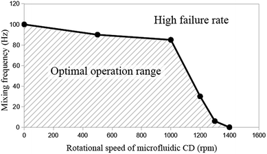 | ||
| Fig. 3 Operational range of the proposed mixing mechanism based on a range of mixing frequency and the rotational speed of the microfluidic CD. | ||
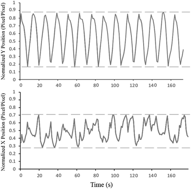
Fig. 4 shows the trajectory of the mixing magnet inside the mixing chamber in the x- and y-axis (please refer to Fig. 2 for x- and y-axis position and direction). For this experiment, the primary CD (microfluidic CD) remained static while the secondary CD was spun to produce an 80 Hz mixing frequency. To produce the trajectory graphs, a video of the microfluidic chamber was captured at 1000 FPS. The motion of the mixing magnet was automatically tracked using specially developed image processing code. As seen from the normalized Y position graph, the mixing magnet perfectly followed the frequency of the secondary CD and fully covered the major radius of mixing chamber. On the other hand, the trajectory of the mixing magnets along the minor radius shows that the mixing magnets hit the right wall of the chamber more than the left wall (more peaks towards the right side). This is due to the high speed of the secondary CD driving the mixing magnets towards the right wall without sufficient time to pull back towards the left wall. However, this partially unbalanced movement does not have a major effect on the quality of the final mixing results.
To evaluate mixing (emulsion) progress, colored frames of the mixing chamber are captured, and histograms and standard deviations of pixel intensities for each plane of the 32 bit RGB images are calculated. Each video is captured at 10 FPS, which is analogous to the speed of the primary (microfluidic) disc, to produce still/non-blurry images. Moreover, the camera exposure is set to 100 μs to prevent blurred images at high speeds. At each frame, the mixing chamber is flashed from different angles (below and at both sides of chamber's short axis) using the developed 120 W LED light sources to provide uniform lighting with minimum shadow effect. Additionally, the bottom of the chamber was covered with a white adhesive sheet as a background to mask the secondary disc and its magnets. To further reduce the effect of the light gradient in the fluid, the region of interest (ROI) is selected to be a central rectangle stretching along the centrifugal force vector (long diameter of the ellipse), where possible non-fluidic distortions and outliers such as the mixing magnet and the venting holes are excluded from the ROI.
Fig. 5 shows the behaviour of the fluid over time during mixing at a constant primary disc speed (600 rpm) and a mixing frequency of 9 Hz. Just before mixing starts (time 0 s), the two liquids form two main regions. Therefore, the chamber has two main color intensities, which are represented by two peaks in the histogram with a high standard deviation. As mixing progresses over time (time 0.5 s), the water and oil are forced to mix by the high mechanical force produced by the oscillation of the mixing magnet. As a result, colored water is forced to form micro and/or nano-drops within the paraffin oil region (emulsion), until the 75th second, where the water is fully converted into drops that are homogeneously distributed along the mixing chamber (homogeneous intensity). Along this progression, the histogram peaks continue to merge towards a single color intensity with a decreasing standard deviation.
Two observations were made from this experiment. First, the green plane of the RGB image rather than the red plane produces more reliable results due to the greenish color of the chamber. This background color could be attributed to the light refraction in the discs. Tests conducted using the red plane produce the expected result pattern. However, the result at each time point is dependent on the magnet position in the chamber; hence, some undesired oscillations appear in the results. This dependency could be attributed to the shadow cast by the mixing magnet when it fidgets along the chamber's short diameter. This can have a significant impact on the histogram due to sensitive nature of the red plane to the red gradient. The second observation is that emulsion progresses quickly to a high percentage of the full emulation within the first 3.5 seconds. However, the full emulsion was reached 72 seconds later. This slow progression region is defined as steady state mixing where the rate of change of the standard deviation is very slow. This is due to the effect of various parameters including the centrifugal force that continues to separate the mixture throughout the process and the challenge to produce sufficiently fine water drops that are equally distributed within the mixing chamber. To test this hypothesis, the 9 Hz mixing experiment was repeated while maintaining a stationary primary CD. Results showed significant drop in time required to achieve full emulation at 4.6 s compared to 75 s when primary CD is rotating. The results show the robustness of the presented active emulsion method even while rotating at high spinning speed.
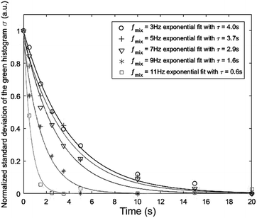
Fig. 6 presents the effect of increasing the mixing frequency on the time needed to obtain the mixing quality in the steady state mixing region. The diminishing standard deviation with time at a certain mixing frequency can approximately be described by the exponential decay equation:  where τ is the time constant. The experiment was conducted at a constant spinning speed of the primary CD (600 rpm) with increasing mixing frequency. As seen, increasing mixing frequencies at a range of 3 Hz, 5 Hz, 7 Hz, 9 Hz and 11 Hz produce a decreasing trend of τ values of 4 s, 3.7 s, 2.9 s, 1.6 s, and 0.6 s, respectively. This result reflects the main advantage of the proposed system where mixing quality and time can rapidly be improved without changing the spinning speed of the primary CD.
Microparticles extraction using water/oil emulsion
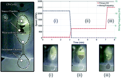
To demonstrate one of the potential applications of the proposed mixing/emulsion setup, particles extraction process is performed. In this process, the attraction among hydrophobic (nonpolar) molecules/compounds is exploit to extract the suspended hydrophobic polystyrene microparticles from its solvent (water). To do so, the above-mentioned water/oil emulsion is performed here between water with suspended polystyrene microparticles and paraffin oil. The same microfluidic CD design in Fig. 2 is utilized for this experiment, but with added destination chamber and connecting microfluidic channels (see Fig. 7(a)). The destination chamber is added to enable relocating water from the mixing chamber to the destination chamber after the suspended particles are extracted using the paraffin oil. The experiment starts with adding 100 μL of water with microparticles in a concentration of 0.05 v/v% (100 ml water with 50 μL particles) and 100 μL of paraffin oil in the mixing chamber (Fig. 7(a)). Once emulsion established, microparticles attract and attach to the oil drops (microparticles will change medium due to hydrophobic/hydrophobic attraction). As shown in Fig. 7(b), this process has three main stages as following:(i) Water/oil emulsion: at this stage, water/oil emulsion is achieved by mixing the two fluids at 11 Hz while spinning the primary CD at 300 RPM for 3 minutes. As emulsion status achieved, microparticles will change medium from water to paraffin oil (see Fig. 7(b-i)).
(ii) Separation: at this stage, water/oil emulsion is separated into two distinct fluids by centrifugation process. To achieve this, the primary CD is spun at 750 RPM for 4 minutes. At the end of this stage, the water will be separated and precipitate at the bottom of mixing chamber while oil with the extracted microparticles will be isolated as a separate layer on the top of the water layer (see Fig. 7(b-ii)).
(iii) Transfer the water to the destination chamber: at this stage, water is forced to transfer from the mixing chamber to the destination chamber by increasing the spinning speed of the primary CD to a speed (2500 RPM) that activate the capillary channel between the two chambers. The volume of the destination chamber is design to barely accommodate the extracted water volume without letting the oil in. At the end of this stage, the water is filtered and successfully extracted from the mixing chamber (see Fig. 7(b-iii)).
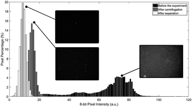
To evaluate the experimental results of the process, pictures of the water portion are captured before the experiment, after centrifugation stage, and after transferring the water to the destination chamber. All experimental pictures are captured using fluorescence inverted microscope. As particles glow under UV exposure, the captured pictures can reflect the concentration of particles after each stage. Fig. 8 shows the histogram of the three acquired pictures. As can be seen in Fig. 8, microparticles concentration in water majorly declined after the separation process and after the transformation of water to the destination chamber. It is believed that the left-over microparticles in water after the separation process is due to the original high concentration of microparticles in water which leads to early saturation in oil (not 100% of particles can be extracted/filtered). It worth to mention here that once particles transfer/attached to oil, it become nearly impossible to return back to water due to interfacial tension even if the two fluids mixed again. Finally, the further reduction in particles concentration after transferring the water from the mixing chamber to the destination chamber is mainly due to the fact that a good amount of microparticles get trapped inside the microchannel.
Conclusion
In this work, the generation of a novel spinning system for microfluidic CDs was developed and evaluated. The developed spinning system consists mainly of two identical brushed DC motors that are controlled independently with the ability to be synchronized. The primary motor spins the primary CD (microfluidic CD), while the secondary motor spins the secondary CD (magnetic CD). The developed system is equipped with a high-speed camera and custom-made lighting system that are synchronized with the spinning motors. Experimental results showed that the developed spinning system can achieve a wide range of mixing frequencies by adjusting the spinning speeds of primary and/or secondary CDs. Moreover, the experimental results proved that the embedded mixing magnet perfectly followed the frequency of the secondary motor at a relatively high spinning speed of the primary CD (microfluidic CD). To evaluate the ability of the developed spinning system to perform efficient active mixing at extreme conditions, an emulsion of oil and water was created. Although the implemented oil produces a high drag force on the mixing magnet, the emulsion process reached a steady state mixing within a couple of seconds and achieved homogeneous mixing at 75 seconds. In addition, microparticles extraction from water to oil was successfully performed using the proposed spinning system. In conclusion, compared to previously proposed active mixing mechanisms using magnetic fields, the proposed dual-motor spinning system can produce much more powerful active mixing independent of the spinning speed of the microfluidic CD. In other words, highly efficient mixing can be performed at any spinning speed of the microfluidic CD without affecting other integrated microfluidic components such as passive valves or pumps.Conflicts of interest
There are no conflicts to declare.Acknowledgements
This research was financially supported by the Seed-fund number SATS27/2016, provided by German Jordanian University – Amman. The authors would like to show their appreciation for the great contribution of Engineers Rabee Jibrin and Mohammad Al-Sharif in building the spinning system.References
- S. Smith, D. Mager, A. Perebikovsky, E. Shamloo, D. Kinahan and R. Mishra, et al., CD-Based Microfluidics for Primary Care in Extreme Point-of-Care Settings, Micromachines, 2016, 7(2), 22 CrossRef.
- M. Madou, J. Zoval, G. Jia, H. Kido, J. Kim and N. Kim, Lab on a CD, Annu. Rev. Biomed. Eng., 2006, 8, 601–628 CrossRef PubMed.
- O. Strohmeier, M. Keller, F. Schwemmer, S. Zehnle, D. Mark and F. von Stetten, et al., Centrifugal microfluidic platforms: advanced unit operations and applications, Chem. Soc. Rev., 2015, 44(17), 6187–6229 RSC.
- S. M. A. Mortazavi, P. Tirandazi, M. Normandie and M. S. Saidi, Efficient batch-mode mixing and flow patterns in a microfluidic centrifugal platform: a numerical and experimental study, Microsyst. Technol., 2017, 23(7), 2767–2779 CrossRef.
- M. Grumann, A. Geipel, L. Riegger, R. Zengerle and J. Ducrée, Batch-mode mixing on centrifugal microfluidic platforms, Lab Chip, 2005, 5(5), 560–565 RSC.
- A. Sayad, F. Ibrahim, S. M. Uddin, J. Cho, M. Madou and K. L. Thong, A Microdevice for Rapid, Monoplex and Colorimetric Detection of Foodborne Pathogens using a Centrifugal Microfluidic Platform, Biosens. Bioelectron., 2017, 100, 96–104 CrossRef PubMed.
- W. Al-Faqheri, T. H. G. Thio, M. A. Qasaimeh, A. Dietzel, M. Madou and A. T. Al-Halhouli, Particle/cell separation on microfluidic platforms based on centrifugation effect: a review, Microfluid. Nanofluid., 2017, 21(6), 102 CrossRef.
- G. R. Aguirre, V. Efremov, M. Kitsara and J. Ducrée, Integrated micromixer for incubation and separation of cancer cells on a centrifugal platform using inertial and dean forces, Microfluid. Nanofluid., 2015, 18(3), 513–526 CrossRef.
- A. T. Al-Halhouli, A. Alshare, M. Mohsen, M. Matar, A. Dietzel and S. Büttgenbach, Passive micromixers with interlocking semi-circle and omega-shaped modules: experiments and simulations, Micromachines, 2015, 6(7), 953–968 CrossRef.
- J.-N. Kuo and B.-S. Li, Lab-on-CD microfluidic platform for rapid separation and mixing of plasma from whole blood, Biomed. Microdevices, 2014, 16(4), 549–558 CrossRef PubMed.
- S. Haeberle, T. Brenner, H. P. Schlosser, R. Zengerle and J. Ducrée, Centrifugal micromixery, Chem. Eng. Technol., 2005, 28(5), 613–616 CrossRef.
- J. Ducree, T. Brenner, S. Haeberle, T. Glatzel and R. Zengerle, Multilamination of flows in planar networks of rotating microchannels, Microfluid. Nanofluid., 2006, 2(1), 78–84 CrossRef.
- Z. Noroozi, H. Kido, M. Micic, H. Pan, C. Bartolome and M. Princevac, et al., Reciprocating flow-based centrifugal microfluidics mixer, Rev. Sci. Instrum., 2009, 80(7), 075102 CrossRef PubMed.
- M. M. Aeinehvand, F. Ibrahim, S. W. Harun, I. Djordjevic, S. Hosseini and H. A. Rothan, et al., Biosensing enhancement of dengue virus using microballoon mixers on centrifugal microfluidic platforms, Biosens. Bioelectron., 2015, 67, 424–430 CrossRef PubMed.
- M. C. Kong and E. D. Salin, Micromixing by pneumatic agitation on continually rotating centrifugal microfluidic platforms, MicrofluidMicrofluidics and nanofluidics, 2012, 13(3), 519–525 CrossRef.
- S. Haeberle, N. Schmitt, R. Zengerle and J. Ducrée, Centrifugo-magnetic pump for gas-to-liquid sampling, Sens. Actuators, A, 2007, 135(1), 28–33 CrossRef.
- H. Kido, M. Micic, D. Smith, J. Zoval, J. Norton and M. Madou, A novel, compact disk-like centrifugal microfluidics system for cell lysis and sample homogenization, Colloids Surf., B, 2007, 58(1), 44–51 CrossRef PubMed.
- W. Liu, D. Sun, C. Li, Q. Liu and J. Xu, Formation and stability of paraffin oil-in-water nano-emulsions prepared by the emulsion inversion point method, J. Colloid Interface Sci., 2006, 303(2), 557–563 CrossRef PubMed.
| This journal is © The Royal Society of Chemistry 2018 |

