 Open Access Article
Fabrication of a blood compatible composite membrane from chitosan nanoparticles, ethyl cellulose and bacterial cellulose sulfate
Zhiming Lia,
Jiazhi Maa,
Rongguo Lia,
Xueqiong Yin *a,
Wenyuan Donga and
Changjiang Pan
 b
b
aHainan Provincial Fine Chemical Engineering Research Center, School of Materials and Chemical Engineering, Hainan University, 58th Renmin Road, Haikou, Hainan 570228, P. R. China. E-mail: yxq88@hotmail.com; Fax: +86 898 66291383; Tel: +86 898 66279161 Tel: +86 13138907588
bFaculty of Mechanical and Materials Engineering, Huaiyin Institute of Technology, Huai'an, Jiangsu 223003, P. R. China
First published on 5th September 2018
Abstract
A heparin-like composite membrane was fabricated through electrospinning chitosan nanoparticles (CN) together with an ethylcellulose (EC) ethanol solution onto a bacterial cellulose sulfate membrane (BCS). Scanning electron microscopy images revealed that there were no chitosan particles in the obtained composite CN-EC/BCS membranes (CEB), indicating CN had been stretched to nanofibers. X-ray photoelectron spectroscopy verified the existence of –NH2 from chitosan and –SO3− from BCS on the surface of CEB membranes. Positively charged CN in the electrospinning solution and negatively charged BCS on the collector increased the electrostatic force and the electrospinning ability of the EC was increased. The membrane was hydrophobic, with a water contact angle higher than 120°. CEB membranes expressed good blood compatibility according to the results of coagulation time and platelet adhesion experiments. No platelets adhered on the surface of the CEB membranes. An inflammatory response was investigated according to activation of the macrophages seeded onto the membranes. Macrophages seeded on CEB membranes are not activated after 24 h incubation.
Introduction
Blood compatibility is one of the key properties of biomaterials in contact with blood.1 When blood touches a foreign material, blood proteins absorb onto the surface and trigger biological responses, such as thrombin formation, platelet activation, blood coagulation, thrombosis, etc. To avoid potential adverse effects on patients, especially thrombosis, a blood-contacting biomaterial should be blood compatible.2 The structural characteristics of a material's surface (including chemical components, topography, morphology, surface charge, and surface wettability) are the key factors affecting the blood compatibility due to the clotting cascade of blood (adsorption of plasma proteins (mainly serum albumin, globulin, fibrinogen, and prothrombin), platelet activation, platelet adhesion and aggregation) is triggered and regulated by the characteristics.3 Materials exhibiting specifically design surfaces, especially those with nanofibrous membranes having similar chemical structures and nanofibers (ranging from 50 to 150 nm in diameter) with the native extracellular matrix (ECM, including proteoglycans, glycosaminoglycans and fibrous proteins) demonstrate good blood compatibility.4Heparin is a naturally occurring anticoagulant, which has been widely used to treat and prevent many diseases, such as deep vein thrombosis, pulmonary embolism, and arterial thromboembolism. Heparin is a mixture of sulfated polysaccharide chains composed of repeating units of D-glucosamine and either L-iduronic or D-glucuronic acids.5 The ionic functional groups, including sulfate, sulfamide, and carboxylate groups, are the key groups of anticoagulant activity of heparin.6,7 Therefore, many blood-contacting materials have been modified to introduce similar structures onto the surface through chemical grafting, plasma deposition, self-assembly to mimic the structure and properties of heparin.8–10 In recent years, many natural polysaccharides, such as chitosan, cellulose, and their derivatives have been modified to mimic heparin. Bacterial cellulose (BC) is an unbranched polymer of β-1,4-linked glucopyranose residues same as plant cellulose (PC),11 which is an exocellular polysaccharide of microbial fermentation production.12 BC is a natural nanofibrous membranes, having ultrafine reticulated fiber structure (3–4 nm (thickness) and 370 ± 80 nm (width)).13,14 BC has been widely used in blood-contacting materials, such as artificial blood vessels, artificial skin, and wound healing materials.15 BC is a good candidate to prepare blood compatible membrane. BC sulfate (BCS) can be utilized as a potential raw blood-contacting biomaterial to mimic heparin owing to the presence of –SO3−, and natural nanofibrous structure of BC.16–18
Electrospinning is an effective methodology for preparing nanofibrous materials with specific chemical structure and morphology,19 which has been used to mimic the surface of blood vessel walls, including chemical structure and morphology. Chitosan is the partly N-deacetylated derivatives of chitin (poly(2-(acetylamino)-2-deoxy-β-(1→4)-D-glucose)) which is the second most abundant natural polysaccharide after cellulose.20 Chitosan has been widely investigated as a potential biomaterial due to its biocompatibility, biodegradability, and multiple biological properties.21 Electrospinning of chitosan has been investigated in recent years.22 Owing to the strong molecular interaction between the highly charged density and high viscosity of chitosan solutions, it is very difficult to electrospin chitosan solely.23,24 Usually, chitosan should be electrospun in special solvents (such as 90% acetic acid,25 trifluoroacetic acid,26 1,1,1,3,3,3-hexafluoro-2-propanol, etc.) or electrospun with the assistant of other polymers (such as poly (vinyl alcohol) (PVA), polyethylene oxide, poly (lactic acid) (PLA), etc) after dissolving in a dilute acid and blending with the assistant polymer solution. In our previous research, we found a new process to electrospin chitosan nanoparticles into nanofibers together with another polymers having flexible polymer chains, such as PLA and PVA.27,28 Ethyl cellulose (EC) is a cellulose derivative which can be dissolved in a variety of organic solvents and have flexible polymer chain.29 Therefore, it is possible to electrospin EC and chitosan nanoparticles together.
Many electrospun nanofibrous membranes have expressed good blood compatibility due to the similarity of the membrane with the ECM.28,30,31 However, there is no report on preparing heparin-like membrane from polysaccharide sulfate through electrospinning up to now. And the electrospinning of positively charged chitosan and negatively charged BCS in one solution is not easy to be carried out due to the aggregation of the solution. Therefore, in this paper, we planned to fabricate a composite membrane from chitosan nanoparticle (CN), EC, and BCS through electrospinning CN/EC emulsions onto a surface modified BCS membrane. The composite membrane was supposed to be blood compatible due to the similar chemical structure and morphology with ECM. The membranes were characterized with Fourier transform infrared spectroscopy (FTIR), X-ray photoelectron spectroscopy (XPS), scanning electron microscopy (SEM), and water contact angles instrument. The blood compatibility of CEB membrane was measured through coagulation times and platelet adhesion.
Experimental
Ethical statement
All experiments were performed in compliance with the ethics guidelines of Hainan University, Haikou, China. And all experiments were approved by the ethics committee at Hainan University. Informed consent was also obtained from human participant of this study.Materials
Chitosan was purchased from Zhejiang Golden Shell Biological Chemical Co., Ltd. (Mw 5 × 10⁵ g mol−1, DD 90%, particle size 2.2 μm). EC (Mw 2.5 × 10⁵ g mol−1) was purchased from Sinopharm Group Chemical Reagent Co., Ltd. NaH2PO4 and NaH(PO4)2 were purchased from Guangzhou Chemical Reagent Factory. All the reagents were used as received. Bacterial cellulose (Mw 6.4 × 10⁵ g mol−1) was purchased from Hainan Yide Food Co., Ltd. and processed according to our previous publication.32Preparation and characterization of BCS
After vacuum dried at 100 °C overnight, a piece of BC membrane was immersed in 100 mL pyridine for 1 h. Then a certain amount of SO3/Py (6 mol SO3/Py per mol AGU) was put into above solution with magnetic stirring for 3 h at room temperature to get surface modified BCS membrane. The obtained membrane was washed 3 times with anhydrous ethanol and then immersed in 1 mol L−1 sodium hydroxide solution for 30 min. Afterwards, the membrane was immersed in distilled water and washed until the filtrate became neutral. Finally, the product was freeze-dried. The sulfate content of BCS was measured using elemental analysis. Fourier transform infrared spectroscopy (FTIR) of BCS membrane was measured with a TENSOR 27 spectrometer in the range of 500–4000 cm−1.Preparation of electrospun CEB membrane
4.8 g EC was put into 30 mL mixture solution of ethanol and deionized (volume ratio 4![[thin space (1/6-em)]](https://www.rsc.org/images/entities/char_2009.gif) :
:![[thin space (1/6-em)]](https://www.rsc.org/images/entities/char_2009.gif) 1). 16 wt% EC solution was obtained after stirring for 2 h. A certain amount of CN (200 mg, 400 mg) obtained by ball milling for 4 h was added into above EC solution with magnetic stirring to prepare the solution for further electrospinning. The electrospinning experiment was carried out on an electrostatic spinning instrument (DT-200, Dalian Dingtong Technology Development Co., Ltd.). In a typical procedure, the electrospinning solution was put into a 25 mL syringe and then pumped into the spray nozzle with a propulsion speed of 0.001 mm s−1. A positive voltage was applied to the polymer solution via a stainless steel syringe needle. The distance between the tip of the needle and the collector was maintained at 10–22 cm. The electrospun polymer fibers were collected on an aluminum foil which was covered with a BCS membrane.
1). 16 wt% EC solution was obtained after stirring for 2 h. A certain amount of CN (200 mg, 400 mg) obtained by ball milling for 4 h was added into above EC solution with magnetic stirring to prepare the solution for further electrospinning. The electrospinning experiment was carried out on an electrostatic spinning instrument (DT-200, Dalian Dingtong Technology Development Co., Ltd.). In a typical procedure, the electrospinning solution was put into a 25 mL syringe and then pumped into the spray nozzle with a propulsion speed of 0.001 mm s−1. A positive voltage was applied to the polymer solution via a stainless steel syringe needle. The distance between the tip of the needle and the collector was maintained at 10–22 cm. The electrospun polymer fibers were collected on an aluminum foil which was covered with a BCS membrane.
Characterization of CEB membranes
The surface morphology of CEB was observed with a S-3000 N scanning electron microscope after gold coating, with the voltage of 10 kV. FTIR spectra were obtained on a TENSOR 27 spectrometer in the range of 500–4000 cm−1. The water contact angle of the film was measured on a SL200K contact angle measurement instrument at 20 °C. A drop of deionized water was dropped onto the sample membranes. The contact angles were calculated using the image processing software CAST™ 2.0. The measurement was reproduced 10 times and the average value was adopted. The surface chemical components of the membranes were analyzed using a X-ray photoelectron spectroscopy (Thermo Scientific Escalab 250Xi, England) equipped with a Al K Alpha X-ray source (powered at 10 mA and 15 kV). The spot size was 400 μm. The pass energy was set at 50 eV for the survey spectrum and the energy step size was 0.100 eV. The pressure in the analysis chamber was around 10−7 Pa. The elemental compositions were determined on the basis of peak areas and sensitivity factor from the C1s, N1s, and O1s peaks by the software CasaXPS (Casa Software, Teignmouth, UK).Blood compatibility measurement
Fresh human blood (whole human fresh blood was collected by venipuncture from a healthy volunteer (man, 23 years old)) mixed with sodium citrate was centrifuged at 3000 rpm for 10 min to obtain platelet-poor plasma (PPP) and platelet-rich plasma (PRP). The specimens (1 cm × 1 cm) were incubated in 800 μL PPP at 37 °C for 20 min. Then, 200 μL PPP was taken to measure in vitro coagulation times, including activated partial thrombin time (APTT), prothrombin time (PT), and thrombin time (TT). The measurement was carried out on a CA-50 blood coagulation analyzer (Sysmex, Japan). To investigate the platelet adhesion of the membranes, 250 μL PRP was poured onto the membrane (0.5 cm × 0.5 cm) and allowed to maintain at 37 °C for 2 h. Then the samples were carefully washed with saline to remove the non-adhered blood cells. The adhered blood cells were fixed by immersing the films into 20 mL 2.5 wt% solution of glutaraldehyde for 1 h at room temperature. The membranes were washed with PBS and then subsequently dehydrated by immersing into a series of ethanol–water solutions (50, 60, 70, 80, 90, 95, and 100% (v/v)) for 30 min each and allowed to evaporate at room temperature. The samples were dried and then observed with a JSM-7100F field emission scanning electron microscopy (JOEL, Japan) after gold coating.Morphology of macrophages by fluorescence microscopy33
Firstly, the electrospun membranes were cut into small round flakes with average diameters of nearly 12 mm, and then sterilized by UV radiation with a power of 20 W for 12 h. The model mouse macrophage cells were obtained from the Sichuan University (China). The cells were cultured in DMEM media containing L-glutamine and 10% fetal bovine serum. The macrophages cells were grown in 24-well tissue culture-treated slides (BD Biosciences) at a concentration of 1 × 10⁴ cells per mL, incubated at 37 °C for 24 h. Non-attached cells were removed by aspiration. Then the samples were put into the 24-cell culture plate and co-cultured with macrophages for 24 h at 37 °C. In order to be observed by fluorescence microscopy (DMIL, Leica, Germany), the macrophage were first fixed with 2.5% glutaraldehyde, and stained by Rodmine123 (Sigma America) and 2-(4-amidinophenyl)-6-indolecarbamidine dihydrochloride (DAPI) (Sigma America) for cytoskeletal structure and nuclei, respectively.Results and discussion
Preparation and characterization of BCS
BC was surface sulfated with SO3/Py (6![[thin space (1/6-em)]](https://www.rsc.org/images/entities/char_2009.gif) :
:![[thin space (1/6-em)]](https://www.rsc.org/images/entities/char_2009.gif) 1 mol
1 mol![[thin space (1/6-em)]](https://www.rsc.org/images/entities/char_2009.gif) :
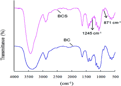
:![[thin space (1/6-em)]](https://www.rsc.org/images/entities/char_2009.gif) mol to AGU) in pyridine at room temperature for 3 h. The degree of sulfation was 0.14 based on the elemental analysis results. The FTIR spectra of BC and BCS were shown in Fig. 1. In both of the spectra, there are characteristic absorbances of polysaccharides at 3430 cm−1, 2910 cm−1, 1160 cm−1, and 1070 cm−1 due to the stretching vibration peak of O–H, stretching vibration peak of C–H, stretching vibration peak of C–O, and stretching vibration peak of C–O–C, respectively. In the spectrum of BCS, two new peaks at 1257 cm−1 and 815 cm−1 appeared, which were corresponded to the stretching vibration peak of O
mol to AGU) in pyridine at room temperature for 3 h. The degree of sulfation was 0.14 based on the elemental analysis results. The FTIR spectra of BC and BCS were shown in Fig. 1. In both of the spectra, there are characteristic absorbances of polysaccharides at 3430 cm−1, 2910 cm−1, 1160 cm−1, and 1070 cm−1 due to the stretching vibration peak of O–H, stretching vibration peak of C–H, stretching vibration peak of C–O, and stretching vibration peak of C–O–C, respectively. In the spectrum of BCS, two new peaks at 1257 cm−1 and 815 cm−1 appeared, which were corresponded to the stretching vibration peak of O![[double bond, length as m-dash]](https://www.rsc.org/images/entities/char_e001.gif) S
S![[double bond, length as m-dash]](https://www.rsc.org/images/entities/char_e001.gif) O and the symmetrical stretching vibration peak of C–O–S, respectively.34,35 The FTIR spectra indicated that partial –OH groups of BC were successfully substituted by –SO3− after sulfation.
O and the symmetrical stretching vibration peak of C–O–S, respectively.34,35 The FTIR spectra indicated that partial –OH groups of BC were successfully substituted by –SO3− after sulfation.
Electrospinning conditions and the morphology of CEB membranes
CN (200 mg, 400 mg) obtained after ball-milled for 4 h was added into 30 mL 16 wt% EC solution for further electrospinning onto BCS membrane at the voltage of 30 kV. Three types of membranes were obtained, including EC membranes having only EC molecules, CE membranes with both EC molecules and CN, and CEB membranes with EC, CN and also BCS. The electrospinning parameters (chemical components and the distance from the nozzle to the collector) and the morphology of the membranes were shown in Table 1 and the SEM images of membranes were shown in Fig. 2.| Samples | CN (mg) | EC (g) | BCSa | Voltage (kV) | Distance (cm) | Morphology |
|---|---|---|---|---|---|---|
| a -: The fibers were spun onto an aluminum foil; +: the fibers were spun onto a BCS membrane. | ||||||
| EC1 | 0 | 4.8 | - | 30 | 10 | Droplets with fibers |
| EC2 | 0 | 4.8 | - | 30 | 16 | Droplets with fibers |
| CE1 | 200 | 4.8 | - | 30 | 10 | Fibers, 30–1600 nm |
| CE2 | 200 | 4.8 | - | 30 | 16 | Fibers, 100–800 nm |
| CE3 | 400 | 4.8 | - | 30 | 10 | Fibers, 150–700 nm |
| CE4 | 400 | 4.8 | - | 30 | 16 | Fibers, 100–1000 nm |
| CEB1 | 200 | 4.8 | + | 30 | 10 | Fibers, 200–1000 nm |
| CEB2 | 200 | 4.8 | + | 30 | 16 | Fibers, 200–500 nm |
| CEB3 | 400 | 4.8 | + | 30 | 10 | Fibers, 150–500 nm |
| CEB4 | 400 | 4.8 | + | 30 | 16 | Fibers, 150–800 nm |
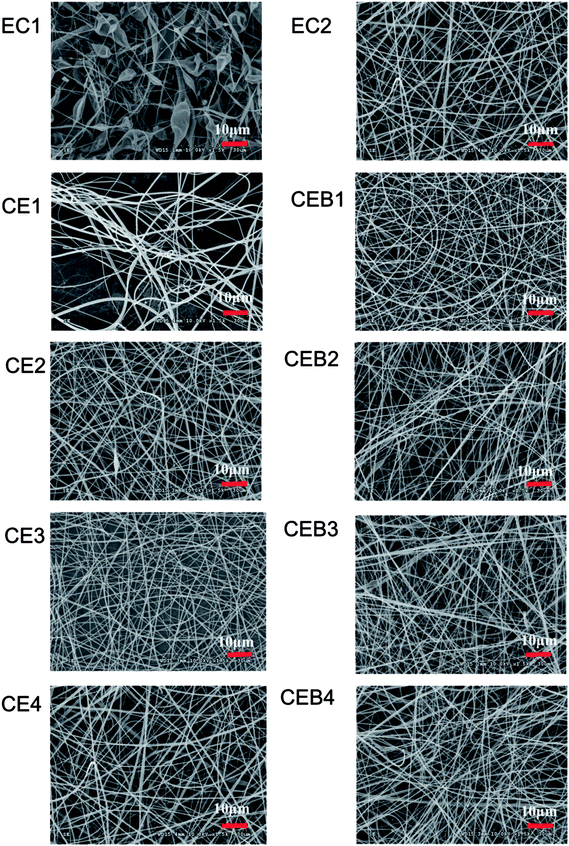 | ||
| Fig. 2 SEM images of EC, CE, and CEB membranes prepared at different electrospinning conditions (the bar of the images was 10 μm). | ||
As shown in Table 1 and Fig. 2, in the EC membranes, only droplets with fibers were obtained at the electrospinning conditions of 30 kV, 10 cm and 30 kV, 16 cm. When 200 mg CN was added to EC solution to obtain a mixer spinning solution (EC/CN), the droplets disappeared and nanofibers were obtained in CE1 and CE2. In CE1, the fiber diameters distributed in 30–1600 nm were obtained. There were two kinds of fibers, very thin fibers with diameter around 30–50 nm and wide fiber with diameters of 1600 nm. When the spinning distance increased to 16 cm (CE2), the diameters of the fibers became more even, being in the range of 100–800 nm. When 400 mg CN was used (CE3, CE4), nanofibers with diameters of 150–700 nm and 100–1000 nm were obtained, respectively. CEB were obtained through electrospinning EC/CN solution onto BCS membranes at the same conditions with CE membranes. Comparing with CE membranes, fibers of CEB had smaller diameters and the diameters distributed narrower. And the distribution of the fibers was more compact in CEB than in CE membranes.
CN is a positively charged polymer. When CN was added to the spinning solution, the electrostatic force of the solution in the electric field increased and overcame the surface tension of the solution more easily.36 Therefore, EC could be stretched to nanofibers at the same spinning conditions after adding CN, and the distribution of the fiber diameters became more even with the increase of CN amount. Furthermore, when negatively BCS was used on the collector, the executing voltage and then the stretching force was increased further.37 The electrostatic forces between EC/CN solution and charged BCS induced the polymers fly to the collector, which resulted in more compact distribution of the fibers in CEB membranes. The results indicated that increasing the charge of the spinning solution38,39 or putting a charged membrane on the collector could help to adjust the spinning executing voltage and modify the morphology of the membrane. Other polymers could be electrospun with this technique to prepare a composite membrane with designed structure.
XPS characterization of CEB membranes
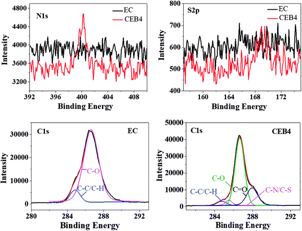
CEB4 and EC2 were measured by XPS. The elemental composition of C1s was given in Table 2 and the representative C1s peaks were presented in Fig. 3. For EC, the C1s peak showed only two components37: (1) carbon only bound to carbon and hydrogen [C–(C, H)] at 284.45 eV; (2) carbon making a single bond with oxygen C–O near 286.62 eV. There was no group of C![[double bond, length as m-dash]](https://www.rsc.org/images/entities/char_e001.gif) O appeared in the spectrum of EC. The C–H/C–C and C–O peak on the surface had an experimentally determined area ratio of 9.57% and 90.43%, respectively. In the spectrum of CEB4, there were two new peaks near 287.95 eV and 285.5 eV, which was attributed to C
O appeared in the spectrum of EC. The C–H/C–C and C–O peak on the surface had an experimentally determined area ratio of 9.57% and 90.43%, respectively. In the spectrum of CEB4, there were two new peaks near 287.95 eV and 285.5 eV, which was attributed to C![[double bond, length as m-dash]](https://www.rsc.org/images/entities/char_e001.gif) O and C–N/C–S, respectively. And the contents of C–C/C–H, C–O, C
O and C–N/C–S, respectively. And the contents of C–C/C–H, C–O, C![[double bond, length as m-dash]](https://www.rsc.org/images/entities/char_e001.gif) O, and C–N/C–S were 4.51%, 67.78%, 22.79%, and 4.92%, respectively.40 Comparing CEB4 with EC2, the existence of C
O, and C–N/C–S were 4.51%, 67.78%, 22.79%, and 4.92%, respectively.40 Comparing CEB4 with EC2, the existence of C![[double bond, length as m-dash]](https://www.rsc.org/images/entities/char_e001.gif) O and C–N/C–S in CEB4 revealed that there were chitosan molecules and –SO3− groups in the surface of CEB4 membrane. –SO3− group from BCS was supposed to be buried by the fibers of EC or chitosan due to CN/EC was sprayed onto BCS membrane attached to the collector. The existence of –SO3− groups on the surface indicated that some BCS polymer chains had shifted from the bottom to the surface. During the process of electrospinning, polymer solution moves forward to the cathode collector in the high voltage electric field.34 Simultaneously, high electrostatic force stretched the negatively charged BCS molecules toward the anode in the direction of the nozzle, which introduces BCS molecules to the surface. The methodology has not been previously reported elsewhere, which demonstrates that a suitable collector could be adopted to prepare an electrospun membrane with tailored structures.
O and C–N/C–S in CEB4 revealed that there were chitosan molecules and –SO3− groups in the surface of CEB4 membrane. –SO3− group from BCS was supposed to be buried by the fibers of EC or chitosan due to CN/EC was sprayed onto BCS membrane attached to the collector. The existence of –SO3− groups on the surface indicated that some BCS polymer chains had shifted from the bottom to the surface. During the process of electrospinning, polymer solution moves forward to the cathode collector in the high voltage electric field.34 Simultaneously, high electrostatic force stretched the negatively charged BCS molecules toward the anode in the direction of the nozzle, which introduces BCS molecules to the surface. The methodology has not been previously reported elsewhere, which demonstrates that a suitable collector could be adopted to prepare an electrospun membrane with tailored structures.
| EC2 | CEB4 | |||||||
|---|---|---|---|---|---|---|---|---|
| Components | C–C/C–H | C–N | C–O | C![[double bond, length as m-dash]](https://www.rsc.org/images/entities/char_e001.gif) O O |
C–C/C–H | C–N/C–S | C–O | C![[double bond, length as m-dash]](https://www.rsc.org/images/entities/char_e001.gif) O O |
| Area% | 9.57 | 0 | 90.4 | 0 | 4.51 | 4.92 | 67.78 | 22.79 |
| Binding energy (eV) | 284.85 | 0 | 286.62 | 0 | 284.75 | 285.5 | 286.64 | 287.95 |
Wettability of CE and CEB membranes
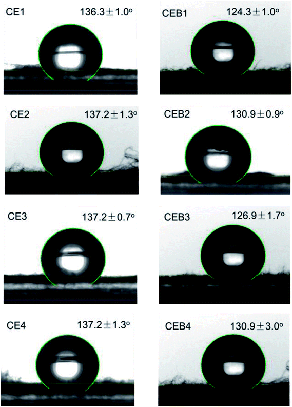
Wettability plays a great role in the application of a biomaterial. To determine whether CE and CEB membranes are suitable to be used in biological conditions, the wettability of CE and CEB membranes was measured. As shown in Fig. 4, the water contact angles (WCA) for all the membranes were higher than 120°, indicating that the samples were all highly hydrophobic.41 The WCA of CE1 and CE2 was 136.3 and 137.2°, respectively. The difference might be due to the amount of CN and the morphology of the two membranes were different.31 Generally, fibers containing 400 mg NCTS (CE3) had higher water contact angles than containing 200 mg NCTS (CE1). This might be owing to hydrophobic –CH2 of chitosan exposed on the surface of CEB.42 CE3 and CE4 had same WCA due to their CN amount and the morphology were similar (shown in Table 1). Comparing CE and CEB membranes, the WCA of CEB was lower than CE membranes, indicating CEB had better hydrophilicity. According to XPS results, there were –SO3− groups on the surface of CEB, which resulted in better hydrophilicity and then lower water contact angle. CEB4 had higher WCA than CEB3 though they had same chemical components. The difference might be due to the morphology difference. As shown in Fig. 1, CEB4 had more pores among the fibers than CEB3, which allowed more hydrophobic air existing in the membrane and resulted in higher hydrophobicity of the membrane.43Blood compatibility of CE and CEB membranes
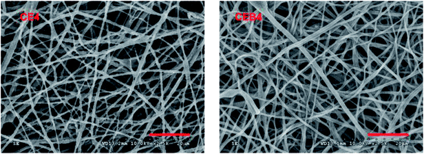
To elucidate the blood compatibility of CE and CEB membranes, in vitro coagulation times and platelet adhesion experiments were carried out. The coagulation times of CE and CEB membranes were shown in Table 3. The results indicated the coagulation times of all samples were within the normal limits9 and essentially same with those of human plasma (the negative control), indicating good blood compatibility of CE and CEB membranes. The blood compatibility might be due to the similarity of the membranes with ECM (chemically and morphologically). However, the anticoagulation times did not prolonged, revealing the membranes had no anticoagulant ability. Though the membrane had similar structure with heparin due to the existence of –SO3− and –OH, the low content of –SO3− groups and their spatial orientation on the surface limited its interactions with the particular proteins in the PPP.44 Therefore, the membranes did not express anticoagulant property.Platelet aggregation experiment is usually carried out to elucidate the blood compatibility of the sample due to platelet adhesion and activation facilitates thrombosis and coagulation. A material with low platelet adhesion and activation means good blood compatibility, while with high degree of platelet adhesion and activation usually is not safe to be used as blood contacting material.45 Therefore, platelet adhesion experiment was carried out to measure the blood compatibility of CE and CEB membranes. Due to the morphology, wettability, and coagulation times were quite similar for CE and CEB membranes, CE4 and CEB4 were chosen to carry out the platelet adhesion experiment. The SEM images of CE4 and CEB4 after contacting with PRP for 2 h were shown in Fig. 5. As shown in Fig. 5, there were no adhered platelets on both of the two membranes, indicating good blood compatibility. There were –SO3−, –OH, –NH2, and –NHOCCH3 groups on the surface due to the existence of chitosan, BCS, and EC in the composite membrane, which ensure the nanofibrous membrane having similar chemical structure and also morphology structure with ECM (with fibers of diameters 50–500 nm).46 The chemical structure enables low absorption of platelets, and the fibers and voids among the fibers form channels which are similar to the microgrooves on the inner blood vessel surface. Blood flows following the direction of microgrooves, resulting in low adhesion of blood cells.47 Therefore, CE and CEB membrane expressed good blood compatibility.
Inflammatory response
The inflammatory response of macrophages on the membranes was investigated to elucidate the probable safety of the membrane in vivo. A foreign material would motivate inflammation response immediately after implanting. During the response processes, macrophages may fuse into foreign-body giant cells to concentrate phagocytic properties which might cause structural and chemical damage of the implanted material.48 Therefore, inflammatory response of macrophages incubated on the membrane was observed by immunofluorescence photography. The images of CE4 and CEB4 after 24 h in vitro incubation with macrophages were shown in Fig. 6. As shown in Fig. 6, the nucleus morphology of macrophages had no obvious difference on CE4, while a much more spreaded skeleton of macrophages was observed. However, the macrophages were mostly in rounded shape and less pseudopods extended on CEB4 surface. And the number of macrophages on CE4 surface was larger on the surface of CEB4. The results indicated that macrophages on CE4 were more activated than those on CEB4. The different inflammatory response of CE4 and CEB4 might be due to the surface chemistry differences of the two membranes. Hydrophilic and anionic substrates provided decrease rates of macrophage adhesion and fusion.49,50 The surface of CEB4 was more anionic than that of CE4 due to the existence of –SO3− and more hydrophilic according to the WCA in Table 3. The results indicate CEB membrane was safer to be used in bioenvironment than CE membrane.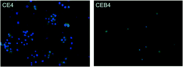 | ||
| Fig. 6 Immunofluorescence photography image of CE4 and CEB4 membranes incubated with macrophages for 24 h in vitro. | ||
Conclusions
CN prepared from ball-milling was successfully electrospun to the surface sulfated BCS membrane with the assistant of EC. Charged CN and BCS increased the electrostatic force and the spinnability of EC/CN solution. CE and CEB membranes had good blood compatibility. No platelets adhered onto the membranes after contacting with PRP and the anticoagulation times were essentially same with those of human plasma. Inflammatory response to macrophages revealed that CEB membrane with anionic –SO3− was safer than CE membrane for application in bioenvironment. The fabrication methodology for composite membrane through electrospinning could be applied in other system to prepare versatile membrane with designed structure by adjusting the components of electrospinning solution and the membrane on the collector.Conflicts of interest
There are no conflicts to decalre.Acknowledgements
The authors appreciate the financial support from the National Science Foundation of China (Project No. 21466011, 21264007), the Key Research and Development Plan of Hainan Province (ZDYF2018232), the Postgraduate Innovation Research Project of Hainan Province (Hys2018-57) and the Key projects of College Students' innovation and Entrepreneurship of Hainan University (Hdcxcyxm201701).References
- F. Renò, V. Traina and M. Cannas, J. Biomater. Sci., Polym. Ed., 2007, 18, 785–797 CrossRef PubMed.
- U. Müller, Medical. Device. Technology., 2008, vol. 19, pp. 32–34 Search PubMed.
- N. Weber, H. P. Wendel and G. Ziemer, Biomaterials, 2002, 2, 429–439 CrossRef.
- E. Ercolani, C. Gaudio and A. Bianco, J. Tissue Eng. Regener. Med., 2015, 9, 861–888 CrossRef PubMed.
- A. Bentolila, I. Vlodavsky, C. Haloun and A. J. Domb, Polym. Adv. Technol., 2000, 11, 377–387 CrossRef.
- Y. Tamada, M. Murata, K. Goto and T. Hayashi, Biomaterials, 2002, 23, 1375–1382 CrossRef PubMed.
- Y. P. Jane, H. A. Metin, A. Ariya, W. Kuhlman and A. M. Mayes, Biomaterials, 2006, 27, 856–865 CrossRef PubMed.
- Y. Li, C. Cao, T. S. Chung and K. P. Pramoda, J. Membr. Sci., 2004, 245, 53–60 CrossRef.
- G. C. Li, P. Yang, W. Qin, M. F. Maitz, S. Zhou and N. Huang, Biomaterials, 2011, 32, 4691–4703 CrossRef PubMed.
- L. R. Wang, H. Qin, S. Q. Nie, S. D. Sun, F. Ran and C. S. Zhao, Acta Biomater., 2013, 9, 8851–8863 CrossRef PubMed.
- H. Bäckdahl, G. Helenius, A. Bodin, U. Nannmark, B. R. Johansson and R. Bo, Biomaterials, 2006, 27, 2141–2149 CrossRef PubMed.
- D. Klemm, D. Schumann, U. Udhardt and S. Marsch, Prog. Polym. Sci., 2001, 26, 1561–1603 CrossRef.
- Y. C. Hsieh, H. Yano, M. Nogi and S. J. Eichhorn, Cellulose, 2008, 15, 507–513 CrossRef.
- X. Yin, C. Yu, X. Zhang, J. Yang, Q. Lin and J. Wang, Polym. Bull., 2011, 67, 401–412 CrossRef.
- F. K. Andrade, R. Costa, L. Domingues, R. Soares and M. Gama, Acta Biomater., 2010, 6, 4034–4041 CrossRef PubMed.
- G. M. De Olyveira, M. L. Dos Santos, P. B. Daltro, P. Basmaji, D. C. D. Gildásio and A. C. Guastaldi, J. Biomater. Tissue Eng., 2014, 4(5), 150–154 CrossRef.
- L. Zhu, J. Qin, X. Yin, L. Ji, Q. Lin and Z. Qin, Polym. Adv. Technol., 2014, 25, 168–172 CrossRef.
- A. Prewett and G. Gontarz, US Pat., US20090149958, 2009.
- D. I. Braghirolli, D. Steffens and P. Pranke, Drug Discovery Today, 2014, 19, 743–753 CrossRef PubMed.
- Q. D. Li, E. T. Dunn, E. W. Grandmaison and M. F. A. Goosen, J. Bioact. Compat. Polym., 1992, 7, 370–397 CrossRef.
- F. Ding, H. Deng, Y. Du, X. Shi and Q. Wang, Nanoscale, 2014, 6, 9477–9493 RSC.
- W. Tighzert, A. Habi, A. Ajji, T. Sadoun and B. O. Daoud, Fibers Polym., 2017, 18, 514–524 CrossRef.
- K. Ohkawa, D. Cha, H. Kim, A. Nishida and H. Yamamoto, Macromol. Rapid Commun., 2010, 25, 1600–1605 CrossRef.
- X. Geng, O. H. Kwon and J. Jang, Biomaterials, 2005, 26, 5427 CrossRef PubMed.
- K. Zhang, D. Peschel, T. Klinger, K. Gebauer, T. Groth and S. Fischer, Carbohydr. Polym., 2010, 82, 92–99 CrossRef.
- L. Fan, X. Zhou, P. Wu, W. Xie, H. Zheng and W. Tan, Int. J. Biol. Macromol., 2014, 66, 245–253 CrossRef PubMed.
- W. Dong, Q. Zeng, X. Yin, H. Liu, J. Lv and L. Zhu, Polym. Compos., 2017, 39, E416–E425 CrossRef.
- J. Lv, X. Yin, Q. Zeng, W. Dong, H. Liu and L. Zhu, J. Polym. Res., 2017, 24, 60 CrossRef.
- D. G. Yu, X. Wang, X. Y. Li, W. Chian, Y. Li and Y. Z. Liao, Acta Biomater., 2013, 9, 5665–5672 CrossRef PubMed.
- X. Chen, J. Wang, Q. An, D. Li, P. Liu, W. Zhu and X. Mo, Colloids Surf., B, 2015, 128, 106–114 CrossRef PubMed.
- X. H. Zhang, H. F. Liu, J. M. Qin, X. Yin, J. Lv and L. Zhu, Bioinspired, Biomimetic Nanobiomater., 2017, 6, 199–207 CrossRef.
- Z. Qin, L. Ji, X. Yin, L. Zhu, Q. Lin and J. Qin, Carbohydr. Polym., 2014, 101, 947–953 CrossRef PubMed.
- G. Li, P. Yang, X. Guo, N. Huang and R. Shen, Cytokines, 2011, 56, 208–217 CrossRef PubMed.
- N. Chiaoprakobkij, N. Sanchavanakit, K. Subbalekha, P. Pavasant and M. Phisalaphong, Carbohydr. Polym., 2011, 85, 548–553 CrossRef.
- B. NKuznetsov, S. A. Kuznetsova, V. A. Levdansky, A. V. Levdansky, N. Y. Vasil'Eva and N. V. Chesnokov, Wood Sci. Technol., 2015, 49, 825–843 CrossRef.
- M. M. Hohman, M. Shin, G. Rutledge and M. P. Brenner, Phys. Fluids, 2001, 13, 2221–2236 CrossRef.
- A. Theron, E. Zussman and A. L. Yarin, Polymer, 2004, 45, 2017–2030 CrossRef.
- V. Ciobotaru, D. Avram and F. Pantilimonescu, Annals of the University of Oradea: Fascicle of Textiles, Leatherwork, 2014, 42, 39–42 Search PubMed.
- B. Sachin Kumar, A. N. Prakrthi, T. Senthil, K. Udaya Bhat and S. Anandhan, Adv. Polym. Technol., 2016, 1–18 Search PubMed.
- P. G. Rouxhet and M. J. Genet, Surf. Interface Anal., 2011, 43, 1453–1470 CrossRef.
- O. Karatum, S. S. Rd, J. S. Griffin, W. Shi and D. L. Plata, ACS Appl. Mater. Interfaces, 2015, 8, 215–224 CrossRef PubMed.
- H. T. Deng, J. J. Wang, Z. Y. Liu and M. Ma, J. Appl. Polym. Sci., 2010, 115, 1168–1175 CrossRef.
- K. Fujimoto, H. Tadokoro, Y. Ueda and Y. Ikada, Biomaterials, 1993, 14, 442–448 CrossRef PubMed.
- M. Ishihara, S. Kishimoto, K. Murakami, H. Hattori and S. Nakamura, Int. J. Pharm. Biol. Sci., 2016, 7, 218–234 Search PubMed.
- E. Salimi, A. Ghaee, A. F. Ismail, M. H. D. Othman and G. P. Sean, Macromol. Mater. Eng., 2016, 301, 771–800 CrossRef.
- E. Ercolani, C. Gaudio and A. Bianco, J. Tissue Eng. Regener. Med., 2015, 9, 861–888 CrossRef PubMed.
- D. Klee and H. Hocker, Biomedical Applications Polymer Blends, 1999, vol. 149, pp. 1–57 Search PubMed.
- J. M. Anderson, Annu. Rev. Mater. Res., 2001, 31, 81–110 CrossRef.
- W. G. Brodbeck, M. S. Shive, E. Colton, Y. Nakayama, T. Matsuda and J. M. Anderson, J. Biomed. Mater. Res., Part B, 2001, 55, 661–668 CrossRef.
- W. G. Brodbeck, J. Patel, G. Voskerician, E. Christenson, M. S. Shive, Y. Nakayama, T. Matsuda, N. P. Ziats and J. M. Anderson, Proc. Natl. Acad. Sci. U. S. A., 2002, 99, 10287–10292 CrossRef PubMed.
| This journal is © The Royal Society of Chemistry 2018 |

