 Open Access Article
Expanding pentafluorouranates: hydrothermal synthesis and characterization of β-NaUF5 and β-NaUF5·H2O†
Alexander T. Chemey ,
Joseph M. Sperling
 and
Thomas E. Albrecht-Schmitt
 *
*
Department of Chemistry and Biochemistry, Florida State University, Tallahassee, FL 32306, USA. E-mail: albrecht-schmitt@chem.fsu.edu
First published on 13th August 2018
Abstract
Two new sodium uranium(IV) pentafluorides were synthesized from uranium dioxide, HF, and NaF using mild hydrothermal conditions. β-NaUF5·H2O has greater lattice energy than previously-known α-NaUF5·H2O and possesses lower symmetry with the latter compound being orthorhombic, whereas β-NaUF5·H2O is monoclinic. Trigonal β-NaUF5 also possesses different connectivity between the [UFn] building units than the α-phase, with higher symmetry and greater lattice energy than orthorhombic α-NaUF5. The single crystal absorption spectra of these compounds are also reported and compared.
Introduction
Fluoride compounds of thorium, uranium, and plutonium are notable for their importance in the processing of materials for nuclear capabilities, but despite considerable efforts for nearly 80 years, new examples continue to be identified. Owing to the low sublimation temperature of UF6, it is routinely employed for the enrichment of natural uranium to increase the amount of fissile 235U in materials for applications in power production and defense applications.1 Interest in this compound as well as U(IV) fluorides has led to the structural elucidation of more than 200 examples that lack uranium–oxygen bonds, though this pales in comparison to actinide oxides lacking fluoride, which exceed 2700 examples.2 While numerous uranium fluorides have been reported, many historic examples do not meet modern standards of characterization and some examples have proven to be mixtures of compounds or simply incorrectly characterized.3–6 The extension of hydrothermal reaction methodologies to uranium fluoride synthesis has resulted in a large expansion of well-characterized examples, especially through the incorporation of organic structure-directing agents.7–9 While many of these compounds contain previously known U(IV) and U(VI) topologies, some previously unknown structure types were identified.10,11More recently, a number of ternary and quaternary hydrated, hydronium, alkali, and transition metal uranium fluorides have been reported for potential applications as phases for separation of actinides or use in molten flux reactors.12–20 These studies yielded the first high-quality structural data of rhombohedral Na7U6F31, as well as the first syntheses of NaUF5 and NaU2F9. The development of the copper-catalyzed U6+/U4+ in situ reduction step by Yeon, et al.19 has led to the production of over a dozen new ternary and quaternary uranium fluorides, but the remarkable stability of Na4CuU6F30 inhibited the production of sodium uranium fluorides until recently.17 Copper appears to catalyse the production of U3F12(H2O) from uranyl solution.19 Resultingly, further work by this research group maintained the use of copper catalyst throughout its work with uranium(IV) fluorides.
The reactions reported herein yielded different products synthesized under similar conditions through simple substitutions in starting materials and the omission of copper, similar to recent reports.12 This brings into question the necessity of the copper catalyst, as well as the choice of starting materials. In this paper, the synthesis, structures, absorption spectra of three sodium pentafluorouranate phases are reported, including the structures of two novel phases – β-NaUF5 and β-NaUF5·H2O.
Experimental section
Synthesis
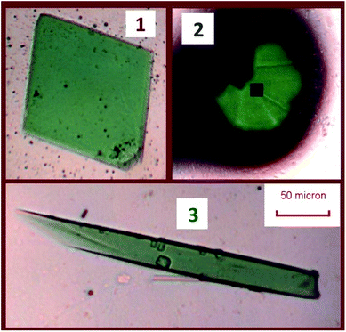
CAUTION! Although depleted uranium is separated from in-grown daughter products and lower in short-lived 235U (t1/2 = 704 million years), 238U (t1/2 = 4.468 billion years) remains a radioactive hazard. Owing to the danger of hydrofluoric acid and uranium, exceptional safety protocols were implemented to ensure risk to personnel was minimized. Reactions were conducted in a fume hood separate from other reactions. Thick HF-safe rubber gloves, a rubber gown, a plastic face shield, and radiation safety equipment were worn, necessitating careful coordination between two experimentalists and extensive practice with analogous reactions.The reported compounds were synthesized hydrothermally in a single reaction with 42.3 mg of NaF (1.01 mmol, Alfa Aesar 99%) and 57.3 mg depleted UO2 (0.212 mmol, Strem), used as received. The reagents were placed in a 10 mL PTFE-lined steel autoclave. 1.00 mL of deionized water was then added to dissolve the sodium fluoride, followed by 1.00 mL 48% HF (Sigma) added dropwise. The autoclave was sealed, then heated in an oven at 200 °C for 1 day, followed by cooling at 5 °C per hour to room temperature. After opening the liner, green crystals were visible under a pale yellow supernatant. Crystals were isolated after the removal of the remaining HF by repeatedly rinsing with chilled water. Crystals were collected by agitating crystals with methanol and removing them from the PTFE liner to a separate plastic vial and allowing the methanol to evaporate. Selections of these products were then isolated under Krytox oil, and single crystals were selected for X-ray diffraction and spectroscopy studies. Three products were obtained from a single reaction. The crystals of these three phases are depicted in Fig. 1.
Crystallographic studies
Single crystals were isolated from Krytox oil with Mitogen mounts, then optically-aligned on a Bruker D8 Quest X-ray diffractometer using a digital camera. Intensity measurements were performed using a IμS X-ray source, a 50 W microfocused sealed tube (Mo Kα, λ = 0.71073 Å) with high-brilliance and high-performance focusing Quazar multilayer optics. Standard APEXIII software was used for determination of the unit cells and data collection control. The intensities of reflections of a sphere were collected by a combination of four sets of exposures (frames). Each set had a different φ angle for the crystal and each exposure covered a range of 0.5° in ω. A total of 1464 frames were collected with an exposure time per frame of 2–10 s, depending on the crystal. SAINT software was used for data integration including Lorentz and polarization corrections. Semiempirical absorption corrections were applied using the program SCALE (SADABS). Atomic coordinates and additional structural information are provided in the ESI† (CIFs). They can be accessed for free at the Cambridge Crystallographic Data Centre (CCDC) with deposition numbers 1854026 and 1854027.Lattice energy calculations
Lattice energy21 was calculated from CIFs reported herein or downloaded from the Inorganic Crystal Structure Database (ICSD).2 The CIF files were then imported into the application VESTA and analyzed with the program MADEL to output lattice energy by the Fourier method.22 MADEL was run with parameters of a 0.4 Å ionic sphere radius and 4 Å−1 reciprocal-space range. Output electrostatic site potentials were given in MJ/(mol-asymmetric unit). To obtain the lattice energy in units of kJ mol−1, the asymmetric unit site potential was then multiplied by the multiplicity of a general position in the relevant crystallographic space group, and then divided by the number of formula units per unit cell (Z). Elements beyond Au were assigned a Born exponent of 14.UV-visible-NIR solid state absorption spectroscopy
UV-visible-NIR absorption spectra were collected on a glass slide under Krytox oil. Using a Craic Technologies 20/20 microspectrophotometer, the data were collected from 350 nm to 1100 nm at room temperature. The exposure time was auto-optimized by the instrument software, and spectra were background corrected for the slide and oil.Powder X-ray diffraction pattern simulation
Simulated powder X-ray diffraction patterns were calculated from the CIF files of the structures with the program Mercury,23,24 a part of the Cambridge Structural Database System (CSDS). The structures of NaUF5 and Na7U6F31 were downloaded from the CCDC repository via their accession numbers. The settings on the powder pattern simulation were as follows: wavelength 1: 1.54056 Å; start: 5° 2θ; stop: 50° 2θ; step: 0.02° 2θ; FWHM 1° 2θ with no preferred orientations.Discussion
Crystallographic descriptions
| Structures | 1 | 2 |
|---|---|---|
| Formula | NaUF5·H2O | NaUF5 |
| Mr | 374.04 | 356.02 |
| Crystal system | Monoclinic | Trigonal |
| Space group | P21/c | P![[3 with combining macron]](https://www.rsc.org/images/entities/char_0033_0304.gif) c1 c1 |
| a [Å] | 7.957(3) | 10.0029(12) |
| b [Å] | 7.027(2) | 10.0029(12) |
| c [Å] | 8.792(3) | 13.0457(16) |
| α [°] | 90 | 90 |
| β [°] | 108.678(7) | 90 |
| γ [°] | 90 | 120 |
| V [Å−3] | 465.7(3) | 1130.4(3) |
| Z | 4 | 4 |
| ρcalcd [g cm−3] | 5.334 | 6.276 |
| μ [mm−1] | 34.961 | 43.176 |
| F(000) | 632 | 1776 |
| Unique reflns | 1118 | 910 |
| GOF on F2 | 1.065 | 1.353 |
| Rint | 0.0633 | 0.0381 |
| R1 (I > 2σ(I)) | 0.0366 | 0.0200 |
| wR2 (all data) | 0.1071 | 0.0382 |
The remaining four μ2-fluorides are corner-shared between uranium sites. The fifth crystallographically-unique fluoride is simply bound to one uranium ion, pointing toward the interstices which host sodium ions. Bond distances are broadly similar to those of 1. Because the single crystallographic uranium ion and all five fluoride ions are on 12g general positions, the pentafluorouranate moiety requires a single positive charge to achieve neutrality. In compound 2, the Na1, Na2, and Na3 ions are located on 4d, 2a, and 2b Wyckoff sites, respectively, and account for 2/3rds of a single general site positive charge. The site designated Na4 has a remarkably close symmetry-generated equivalent atom 1.2 Å away from itself due to a nearby 6f special position at (x,0,1/4). Attempts to fix the ion to the two-fold special position led to abnormally high thermal parameters, with either restricted or free refinement of occupancy, and a non-positive definite atom. The reported 12g general position was selected, and Na4 occupancy was set to 1/3rd. Na1 and Na2 are surrounded by distorted octahedra of fluoride anions with Na–F distances from 2.105(4) Å to 2.337(5) Å. Na3 is surrounded by an icosahedron with Na–F bond lengths of 2.715(4) Å and 2.739(5) Å. By contrast, Na4 at the general position has six fluoride anions surrounding it in a strongly distorted octahedron; if considered at the special position, it is surrounded by a tetragonal bipyramid, with equatorial fluoride anions at-distances of 2.224(10) Å and 2.401(8) Å, while the axial fluorides are at a distance of 2.72(2) Å. Details on the structural refinement may be found in Table 1.
Structural comparisons and context
α-NaUF5·H2O was previously synthesized from evaporation by photochemical reduction in a solution with uranyl nitrate, sodium fluoride, and quinic acid.27 This phase crystallized in the space group Pbcn, and featured layers stacked along the c-axis with two water molecules on 4c inter-layer Wyckoff Sites. By contrast, 1 has only one crystallographic water site, and crystallizes in P21/c with stacking along the a-axis. The layer packing is the most important differentiation between the structures. Compound 1 features a checkerboard pattern when viewed down the stacking axis, with layers eclipsed for a simple AAAA packing structure. By contrast, the α-NaUF5 layers are slightly slipped from one layer to another, making water-containing voids in an ABAB packing motif.The inter-layer distance is greater in 1 (7.957 Å) than in α-NaUF5·H2O (7.521 Å), which reduces electrostatic repulsion. The slipped configuration of the α-phase increases distance between uranium atoms in alternating layers slightly, from 7.521 Å to 7.749 Å; this corresponds to a staggering distance from the A–A line between uranium sites of 1.863 Å. A comparison of relevant intra-layer distances in the alpha and beta phases are given in Table 2.
| α-NaUF5·H2O27 | β-NaUF5·H2O (1) | |
|---|---|---|
| U–F non-bridging bond length (Å) | 2.157(4) | 2.170(7) |
| U–F (μ2) bond lengths (Å) | 2.312(4)–2.420(4) | 2.323(5)–2.435(5) |
| U–U double-fluoride bridge distances (Å) | 3.9280(4)–3.9580(4) | 3.9422(11)–3.4699(11) |
| U–U single-fluoride bridge distance (Å) | 4.5430(4) | 4.5629(13) |
Calculation of hydrogen positions in 1 from VDPs were aided by the large solid angle coverage of Na1 and a symmetry-generated equivalent ion (16.34% 4θ and 13.86% 4θ, respectively) (ESI Table 1†). There was no clear conformational preference for hydrogen–fluorine interactions in the anion-only VDP (ESI Table 2†). As water has two lone pairs, the clear preference is for the lone pairs of electrons to point towards the sodium cations and the hydrogen ions to point away from the cations. Calculations of ideal hydrogen positions 0.87 Å away from the oxygen site in the plane perpendicular to the Na1–O–Na1 plane and inclusive of the Na1–O–Na1 bisecting vector were generated. DANG and DFIX parameters to restrict O–H and H–H distances which centered on the calculated sites were applied, as were DANG parameters to ensure H–Na distances were greater than 2.84 Å. All-atom VDPs and anion-only VDPs can be found in ESI Fig. 3.†
Calculations of lattice energy that include the calculated hydrogen positions suggest that compound 1 is more electrostatically stable than the alpha phase compound by 40 kJ mol−1. Calculations of lattice energy without hydrogen positions considered suggest that compound 1 is 37 kJ mol−1 less electrostatically stable than the alpha phase. As Table 2 indicates, there are minimal differences in intra-layer distances. Indeed, the wireframe comparison of the uranium–uranium connection (Fig. 2) makes it plain to see that the α-phase connectivity is generated by slipping the β-phase connection template and superimposing it over the original. Resultingly, comparisons in hydrogen bonding is of thermodynamic interest in the stability of the phases. Despite the greater density of the alpha hydrate (5.39 g cm−3 vs. 5.334 g cm−3), it appears that the hydrogen bonding of the single water site is more stabilizing than the disordered water sites of the previously-reported phase. It is possible that a thermodynamic trap was overcome by addition of energy to the system in the hydrothermal synthesis of 1, producing the more stable phase.
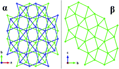 | ||
| Fig. 2 Wireframe comparison of uranium–uranium networks in α-NaUF5·H2O and β-NaUF5·H2O. The alternating colors on the left are the staggered layers. | ||
2 has broadly-similar connectivity and symmetry to a series of quaternary Na4MU6F30 compounds, where M2+ is a divalent transition metal. Both structures crystallize in P![[3 with combining macron]](https://www.rsc.org/images/entities/char_0033_0304.gif) c1 in green hexagons with strong absorptivity from 600 to 650 nm.17 Where α-NaUF5 crystalizes with a linear chain structure of alternating dimer bowties connected to other dimers by corner-sharing uranium–fluorine bonds down the b-axis, β-NaUF5, like the quaternary compounds of Yeon, et al., forms a helical chain down the c-axis which creates hexagonal voids. The quaternary compounds may be regarded as a doubling of structure 2, with Na2 (2a Wyckoff site) replaced by a divalent metal. In these compounds, just as in 2, there was a partly-occupied disordered sodium site 0.6 Å away from a 6f special position. In a series of quaternary sodium trivalent metal uranium fluorides (Na3MU6F30), the disordered Na4 site is totally excluded, as the trivalent metal satisfies the charge balance requirement with only three sodium sites.16 Both families of crystals form hexagonal blocks, and absorption spectra of 2 and the quaternary species (Fig. 8 in Yeon, et al.16,17) match very well. A polyhedral comparison of 2 and Na4CuU6F30 is presented in Fig. 3, as well as a cation map viewed down the a-axis, illustrating the similarity between the structures and the location of Cu2+ in the quaternary structure. A comparison between 2 and Na4CuU6F30 U–F bond lengths can be found in ESI Table 3.†
c1 in green hexagons with strong absorptivity from 600 to 650 nm.17 Where α-NaUF5 crystalizes with a linear chain structure of alternating dimer bowties connected to other dimers by corner-sharing uranium–fluorine bonds down the b-axis, β-NaUF5, like the quaternary compounds of Yeon, et al., forms a helical chain down the c-axis which creates hexagonal voids. The quaternary compounds may be regarded as a doubling of structure 2, with Na2 (2a Wyckoff site) replaced by a divalent metal. In these compounds, just as in 2, there was a partly-occupied disordered sodium site 0.6 Å away from a 6f special position. In a series of quaternary sodium trivalent metal uranium fluorides (Na3MU6F30), the disordered Na4 site is totally excluded, as the trivalent metal satisfies the charge balance requirement with only three sodium sites.16 Both families of crystals form hexagonal blocks, and absorption spectra of 2 and the quaternary species (Fig. 8 in Yeon, et al.16,17) match very well. A polyhedral comparison of 2 and Na4CuU6F30 is presented in Fig. 3, as well as a cation map viewed down the a-axis, illustrating the similarity between the structures and the location of Cu2+ in the quaternary structure. A comparison between 2 and Na4CuU6F30 U–F bond lengths can be found in ESI Table 3.†
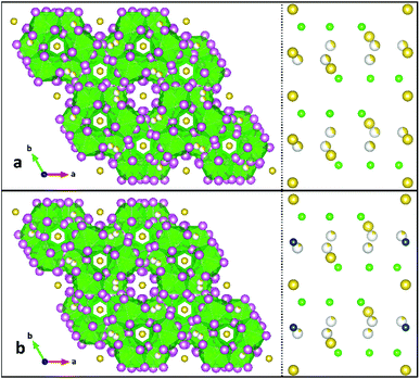 | ||
| Fig. 3 Comparison of product 2 (top, a) to Na4CuU6F30 (ref. 12) (bottom, b). The left side is a polyhedral representation of the structures viewed down the c-axes, while the right side is a simplified map of the cation sites, viewed down the a-axes. Uranium is illustrated by green spheres and polyhedra, sodium is yellow, and copper is blue. Partial occupancy is illustrated by an incompletely-colored sphere. | ||
When the structures of 2 was first obtained and 3 was identified as NaUF5 in the literature,12 it seemed unreasonable to expect two radically different structures with the same stoichiometry from the same reaction. In the same paper which published the structure of α-NaUF5, the structure of (H3O)U3F13 was presented, the first structurally-characterized hydronium uranium fluoride, so a reevaluation of Na3 and Na4 in 2 was therefore considered, with the possibility that their larger volumes might indicate hydronium sites instead. This does not appear to be the case, and we therefore report 2 as the second phase of NaUF5. Comparison of important bond lengths between phases of NaUF5 are given in Table 3. Calculations of lattice energy determined that 2 is more stable than α-NaUF5 by 112 kJ mol−1. This is likely due to 2 crystallizing with much higher symmetry, despite the slightly greater density of the prior phase.
| α-NaUF5 (3)7 | β-NaUF5 (2) | |
|---|---|---|
| U–F non-bridging bond length (Å) | 2.134(2) | 2.196(4) |
| U–F (μ2) bond lengths (Å) | 2.3100(17)–2.486(2) | 2.287(4)–2.435(4) |
| U–U fluoride bridge distances (Å) | 3.9767(3)–4.0966(3) | 4.0442(4)–4.1019(6) |
| U–U single-fluoride bridge distances (Å) | 4.4993(3) | 4.5235(5)–4.5480(7) |
UV-visible-NIR absorption spectroscopy discussion
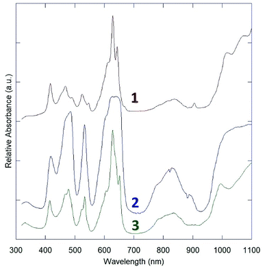
The three obtained spectra presented in are arranged from top to bottom as 1, 2, 3 in Fig. 4. All three indicate only U(IV) absorption features.28The absorption spectra of 1 and 3 are nearly identical, with only subtle differences in the peaks at ∼550 nm and an additional peak in the spectrum of 1 around 900 nm. This is likely attributable to the layer structures of 1 and 3, and similar connectivity between uranium centers. Their spectra feature sharp f–f transitions in the region from 400 nm to 700 nm, which appear to be split by crystal-field effects.
2 has a starkly different absorption spectrum, with broad features at the primary U(IV) absorption bands in the 400–500 nm and 600–660 nm regions, without resolvable crystal-field effects. To ensure that this spectrum was not blunted due to high absorptivity, large crystal size, and limited detector efficiency below ∼10% transmission, several spectra with different crystals and instrument settings were collected, but all matched the spectrum reported in Fig. 4. This spectrum is virtually identical to the reported structures of quaternary sodium uranium fluorides, which were collected by diffuse reflectance spectroscopy.16,17 The absorption spectra of the quaternary phases may therefore be considered dominated by uranium coordination features, with minimal interaction from other metal fluorides in the structure.
The historical powder XRD uncertainty of NaUF5 and Na7U6F31
Although there was reference made to an isolated structure of NaUF5 prior to that of Klepov, et al.,12 the identity of the product was disputed, as no single-crystal structure was obtained.29 Early work with the early actinide fluorides during the Manhattan project relied on powder diffraction and calculation of structures from isomorphous analogue lanthanide and transition metal complexes.4–6 Due to the limitations of the methods of that time that there was controversy over whether products identified as NaUF5 might rather be Na7U6F31.29,30 The results presented here support the possibility that the either of or a combination of both compounds 2 and 3 could readily be confused for Na7U6F31. The production of 2 makes it more reasonable that such confusion might have occurred, as both Na7U6F31 and compound 2 have relatively high symmetry (R![[3 with combining macron]](https://www.rsc.org/images/entities/char_0033_0304.gif) H and P
H and P![[3 with combining macron]](https://www.rsc.org/images/entities/char_0033_0304.gif) c1). Simulated Kα-Cu powder patterns from 5° to 50° 2θ for compound 2 and compound 3 with Na7U6F31 are presented in Fig. 5.
c1). Simulated Kα-Cu powder patterns from 5° to 50° 2θ for compound 2 and compound 3 with Na7U6F31 are presented in Fig. 5.
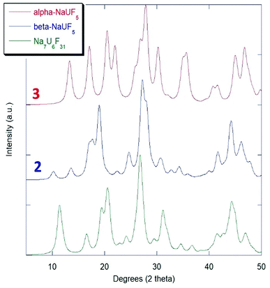 | ||
| Fig. 5 Simulated powder XRD comparison of NaUF5 phases with Na7U6F31.7 | ||
Conclusions
This article describes the synthesis, structures, and solid-state absorption spectroscopy of two new sodium pentafluorouranate phases, β-NaUF5·H2O, and β-NaUF5. This synthesis of these new phases, as well as previously-reported α-NaUF5, was accomplished from hydrofluoric acid solution and uranium dioxide under mild hydrothermal conditions. This eliminates the in situ reduction step which was previously required by those exploring the alkali uranium fluorides. The structures of α- and β-NaUF5·H2O are remarkably similar in uranium connectivity, with differences primarily due to different layer packing. α- and β-NaUF5 were both synthesized in this reaction, despite vastly different structures and connectivity. The beta phases of both the pentafluorouranate and pentafluorouranate hydrate have greater lattice energy than their previously-reported peers. That new products were synthesized from reactions nearly identical to the literature, simply by changing the uranium starting material suggests that new phases of alkali uranium fluorides may yet be discovered by utilizing different starting materials.Conflicts of interest
There are no conflicts to declare.Acknowledgements
This research was supported by the Center for Actinide Science and Technology (CAST), an Energy Frontier Research Center (EFRC) funded by the US Department of Energy (DOE), Office of Science, Basic Energy Sciences (BES), under award number DE-SC0016568.Notes and references
- B. Weinstock and R. Crist, The Vapor Pressure of Uranium Hexafluoride, J. Chem. Phys., 1948, 16, 436–441 CrossRef.
- M. Hellenbrandt, The Inorganic Crystal Structure Database (ICSD)—Present and Future, Crystallogr. Rev., 2004, 17–22 CrossRef.
- R. A. Penneman, in Proceedings of the Actinides – 1981 Conference, Pacific Grove, California, USA, 10-15 September 1981, Pergamon Press, 1982, pp. 57–80 Search PubMed.
- W. Zachariasen, Crystal chemical studies of the 5f-series of elements. XII. New compounds representing known structure types, Acta Crystallogr., 1949, 388–390 CrossRef.
- W. Zachariasen, Crystal chemical studies of the 5f-series of elements. XXII. The crystal structure of K3UF7, Acta Crystallogr., 1954, 792–794 CrossRef.
- W. Zachariasen, Double Fluorides of Potassium or Sodium with Uranium, Thorium, or Lanthanum, J. Am. Chem. Soc., 1948, 70, 2147–2151 CrossRef.
- P. M. Almond, L. Deakin, M. J. Porter, A. Mar and T. E. Albrecht-Schmitt, Low-Dimensional Organically Templated Uranium Fluorides (C5H14N2)2U2F12·2H2O and (C2H10N2)U2F10: Hydrothermal Syntheses, Structures, and Magnetic Properties, Chem. Mater., 2000, 12, 3208–3213 CrossRef.
- P. M. Almond, L. Deakin, A. Mar and T. E. Albrecht-Schmitt, Hydrothermal Synthesis, Structure, and Magnetic Properties of a Layered Organically Templated Uranium Aquofluoride: [C5H14N2][U2F10(H2O)], Inorg. Chem., 2001, 40, 886–890 CrossRef.
- P. M. Almond, L. Deakin, A. Mar and T. E. Albrecht-Schmitt, Hydrothermal Syntheses, Structures, and Magnetic Properties of the U(IV) Fluorides (C5H14N2)2U2F12·5H2O and (NH4)7U6F31, J. Solid State Chem., 2001, 158, 87–93 CrossRef.
- R. E. Sykora, M. Ruf and T. E. Albrecht-Schmitt, Organically Templated Zirconium Fluorides: Hydrothermal Syntheses, Structural Relationships, and Thermal Behavior of (C2H10N2)Zr2F10·H2O and (C4H12N2)ZrF6·H2O, J. Solid State Chem., 2001, 159, 198–203 CrossRef.
- C. E. Talley, A. C. Bean and T. E. Albrecht-Schmitt, Hydrothermal Syntheses of Layered Uranium Oxyfluorides: Illustrations of Dimensional Reduction, Inorg. Chem., 2000, 39, 5174–5175 CrossRef PubMed.
- V. V. Klepov, J. B. Felder and H.-C. zur Loye, Synthetic Strategies for the Synthesis of Ternary Uranium (IV) and Thorium (IV) Fluorides, Inorg. Chem., 2018, 57, 5597–5606 CrossRef PubMed.
- J. Felder, J. Yeon, M. Smith and H.-C. zur Loye, Application of a mild hydrothermal method to the synthesis of mixed transition-metal(II)/uranium(IV) fluorides, Inorg. Chem. Front., 2017, 4, 368–377 RSC.
- J. B. Felder, J. Yeon, M. D. Smith and H.-C. zur Loye, Compositional and Structural Versatility in an Unusual Family of anti-Perovskite Fluorides: [Cu(H2O)4]3[(MF6)(M′F6)], Inorg. Chem., 2016, 55, 7167–7175 CrossRef PubMed.
- J. Yeon, M. D. Smith, J. Tapp, A. Möller and H.-C. zur Loye, Mild hydrothermal crystal growth of new uranium(IV) fluorides, Na3.13Mg1.43U6F30 and Na2.50Mn1.75U6F30: Structures, optical and magnetic properties, J. Solid State Chem., 2016, 236, 83–88 CrossRef.
- J. Yeon, M. D. Smith, G. Morrison and H.-C. zur loye, Trivalent Cation-Controlled Phase Space of New U(IV) Fluorides, Na3MU6F30 (M = Al3+, Ga3+, Ti3+, V3+, Cr3+, Fe3+): Mild Hydrothermal Synthesis including an in Situ Reduction Step, Structures, Optical, and Magnetic Properties, Inorg. Chem., 2015, 54, 2058–2066 CrossRef PubMed.
- J. Yeon, M. D. Smith, J. Tapp, A. Möller and H.-C. zur Loye, Application of a Mild Hydrothermal Approach Containing an in Situ Reduction Step to the Growth of Single Crystals of the Quaternary U(IV)-Containing Fluorides Na4MU6F30 (M = Mn2+, Co2+, Ni2+, Cu2+, and Zn2+) Crystal Growth, Structures, and Magnetic Properties, J. Am. Chem. Soc., 2014, 136, 3955–3963 CrossRef PubMed.
- J. Yeon, M. D. Smith, J. Tapp, A. Möller and H.-C. zur Loye, Mild Hydrothermal Crystal Growth, Structure, and Magnetic Properties of Ternary U(IV) Containing Fluorides: LiUF5, KU2F9, K7U6F31, RbUF5, RbU2F9, and RbU3F13, Inorg. Chem., 2014, 53, 6289–6298 CrossRef PubMed.
- J. Yeon, M. D. Smith, A. S. Sefat, T. T. Tran, S. P. Halasyamani and H.-C. zur Loye, U3F12(H2O), a Noncentrosymmetric Uranium(IV) Fluoride Prepared via a Convenient In situ Route that Creates U4+ under Mild Hydrothermal Conditions, Inorg. Chem., 2013, 52, 8303–8305 CrossRef PubMed.
- A. C. Bean, T. A. Sullens, W. Runde and T. E. Albrecht-Schmitt, Hydrothermal Preparation of Nickel(II)/Uranium(IV) Fluorides with One-, Two-, and Three-Dimensional Topologies, Inorg. Chem., 2003, 42, 2628–2633 CrossRef PubMed.
- A. F. Kapustinskii, Lattice energy of ionic crystals, Q. Rev., Chem. Soc., 1956, 10, 283–294 RSC.
- K. Momma and F. Izumi, VESTA: a three-dimensional visualization system for electronic and structural analysis, J. Appl. Crystallogr., 2008, 41, 653–658 CrossRef.
- C. F. Macrae, P. R. Edgington, P. McCabe, E. Pidcock, G. P. Shields, R. Taylor, M. Towler and J. van de Streek, Mercury: visualization and analysis of crystal structures, J. Appl. Crystallogr., 2006, 39, 452 CrossRef.
- C. R. Groom, I. J. Bruno, M. P. Lightfoot and S. C. Ward, The Cambridge structural database, Acta Crystallogr., 2016, B72, 171–179 Search PubMed.
- V. A. Blatov, Voronoi–Dirichlet Polyhedra in Crystal Chemistry: Theory and Applications, Crystallogr. Rev., 2004, 10, 249–318 CrossRef.
- V. A. Blatov, A. P. Shevchenko and V. N Serezhkin, TOPOS3.2: a new version of the program package for multipurpose crystal-chemical analysis, J. Appl. Crystallogr., 2000, 33, 1193 CrossRef.
- A. Fischer and Z. Szabo, Sodium pentafluorouranate (IV) monohydrate, Na[UF5]·H2O, Acta Crystallogr., Sect. E: Crystallogr. Commun., 2004, E60, i45–i46 CrossRef.
- D. E. Hobart, PhD thesis, University of Tennessee – Knoxville, 1981.
- D. Brown, Halides of the Lanthanides and Actinides, Wiley-Interscience, 1st edn, 1968 Search PubMed.
- R. E. Thoma, Cation size effects in complex fluoride compound formation, Inorg. Chem., 1962, 1, 220–226 CrossRef.
Footnote |
| † Electronic supplementary information (ESI) available. CCDC 1854026 and 1854027. For ESI and crystallographic data in CIF or other electronic format see DOI: 10.1039/c8ra05780j |
| This journal is © The Royal Society of Chemistry 2018 |

