 Open Access Article
Five-fold twinned β-PbF2 nanocrystals in oxyfluoride glass ceramics
Yuao Guo ,
Lijuan Zhao*,
Yuting Fu,
Pan Dong,
Liying Guo and
Hua Yu*
Key Laboratory of Weak-Light Nonlinear Photonics, Ministry of Education, School of Physics, Nankai University, Tianjin 300071, China. E-mail: zhaolj@nankai.edu.cn; yuhua@nankai.edu.cn
First published on 5th December 2018
Abstract
Oxyfluoride glass ceramics (GCs) doped with trivalent lanthanide ions (Ln3+) have been prepared using a conventional melting–quenching method and studied by X-ray diffraction (XRD). β-PbF2 nanocrystals (NCs) doped with Ln3+ ions (β-PbF2:Ln3+) in GCs were released from the GCs by etching off the glass matrix. β-PbF2:Ln3+ NCs can be clearly observed by eliminating the influence of the glass matrix. The nanotwinned structures of β-PbF2:Ln3+ NCs, including two-fold twinned NCs and five-fold twinned NCs, were examined using high-resolution transmission electron microscopy (HRTEM). The five-fold twinned phenomenon in metal fluorides with strong ionicity in oxyfluoride GCs is reported for the first time. Based on detailed analysis of the twinned NC structure, the twinning mechanism of β-PbF2:Ln3+ NCs was proposed. Ln3+ ions and ‘sublattice melting’ of fluorine ions (F−) in β-PbF2 play extremely important roles in the formation of five-fold twinned β-PbF2:Ln3+ NCs. The nanotwinned structures reported here may have far-reaching significance with respect to the further application of oxyfluoride glass ceramics doped with rare-earth elements and NC fabrication.
Introduction
Five-fold twinned crystals are widespread in bulk crystalline materials and upon size reduction to the nanometre scale.1 Owing to the presence of high-density twinned defects and diffuse elastic strain, twinning structures might have more interesting properties than the corresponding single crystalline structures.2 Pt and Pd alloy icosahedral nanocrystals (NCs) show much stronger activity for methanol oxidation than that of tetrahedral Pt and Pd alloy NCs due to the multiply twinned defects.3 In recent decades, five-fold twinned NCs have been found in various substances, from elemental substances (Si, C, Pb, Fe, Co, Ni, Cu, Al, Cr, Ru, Rh, Pd, Ag, Ir, Pt, and Au) and alloys to compounds such as B6O, SnO2, Fe2O3, BN, and GaP.4–18 These compounds are almost all comprised of group three and five elements or their oxides with weak ionicity. In contrast, twin crystals have rarely been found in metal fluorides with strong ionicity. The synthesis of five-fold twinned crystals can be achieved using: (i) vapor structure techniques, including physical or chemical vapor deposition on substrates and particle growth by aggregation under an inert gas atmosphere; (ii) liquid structure techniques, including growth from solution via chemical precipitation or electrode deposition and high melt growth; and (iii) solid structure techniques, including precipitation from solid solutions in crystalline or glassy hosts, solid structure crystallization from an amorphous structure, and solid structure reduction by reactive gases.10 These synthetic methods are in situ crystal growth processes, especially the methods for high-pressure melt growth and solid structure crystallization from the amorphous structure, where the size and morphology of the crystal is restricted to the nanometre scale owing to the binding effect of the high-pressure environment and amorphous matrix.Oxyfluoride glass ceramics (GCs) are a new class of photonic materials comprised of fluoride crystallites and oxide glasses. Metal fluoride crystallites19,20 with crystallite sizes ranging from 5 to 100 nm are considered to be usually surrounded by an oxide glass matrix. Oxyfluoride GCs are prepared using a conventional melting–quenching method.21,22 Compared with the preparation techniques for five-fold twinning mentioned above, the glass ceramics system has the characteristics of both solid structure crystallization from the amorphous structure and high-pressure melt processing.
After the pioneering work by Wang and Ohwaki23 in 1993, rare earth doped oxyfluoride GCs have attracted much research interest owing to the unique comprehensive low phonon energy properties of fluoride crystals and the outstanding durability and mechanical properties of oxide glass.24–27 Many studies have focused on the optical properties of oxyfluoride GCs, while the nanostructures of NCs in GCs have received only occasional attention,27,28 with many controversies remaining regarding the size and shape of NCs in GCs, mainly due to the influence of silicate glass matrix on the clear study of nanocrystal structures. Only a fundamental understanding of the nanostructure and growth of NCs in GCs will allow the photonic properties of GCs to be adjusted and used. A novel method for further studying the nanostructures of NCs in GCs is needed because nanostructures can significantly influence their special chemical and physical properties.
Herein, we report five-fold twinned NCs of β-PbF2 with strong ionicity in an oxyfluoride GC system for the first time. We present an approach to eliminating the influence of the silicate glass matrix and distinctly observe the NC structure with a narrow crystallite size distribution (mainly 7 nm) for the first time. Furthermore, twinned NCs were confirmed to be widespread in GCs. These prepared twinned NC structures underwent detailed analysis and a twinning mechanism was proposed, in which Ln3+ ions and ‘sublattice melting’ of F− ions in β-PbF2 were the dominant factors in twinning growth. According to comprehensive analysis of the NC nanostructures in GCs, twinning growth might play a fundamental role in the shape-controlled synthesis and optoelectronic properties of NCs.
Experimental
Oxyfluoride GCs were prepared with the following composition (in mol%): 45.5SiO2–40PbF2–10CdF2–0.5Er2O3–4Yb2O3 using a conventional melting–annealing method. CdF2 was introduced using Cd(NO3)2·4H2O and NH4F. The starting materials (about 20 g) were mixed well and then melted in a covered platinum crucible at 1000 °C for 2 h. The glass precursor was obtained by pouring the molten substance into a copper pan rapidly at room temperature. The glass precursor was then annealed at 440 °C for 8 h to form glass ceramics co-doped with Er3+ and Yb3+ (β-PbF2:Ln3+).Corrosion treatment was used to remove the silicate glass matrix. The corrosive agent was prepared mixing glacial acetic acid (2 mL) and NH4F (0.08 g) with deionized water (18 mL). Glass ceramics powder (0.2 g) was then mixed thoroughly with the as-prepared corrosive agent with vigorous stirring. Oleic acid (OA, 5 mL) was added as a surface-modification agent to prevent NC aggregation. The reaction was continued for 24 h to ensure that NCs were released completely from the glass matrix. When the reaction was finished, a white precipitate was obtained. The precipitate was separated by centrifuging at 3000 rpm and then washing with methanol and deionized water three times. The white precipitate was dried in air at 80 °C, with the final product obtained as a white powder and then dispersed in ethanol. A little of the ethanol solution containing nanocrystals was dropped onto a copper film for natural air drying and then used for TEM analysis.
X-ray diffraction (XRD) measurements were performed to identify the crystallization phases of the NCs using a powder diffractometer (D/Max-2500) using CuKα radiation. The morphology and size of the nanocrystals in the glass ceramic were obtained by high-resolution transmission electron microscopy (HRTEM, 2100F, JEOL, Japan), for which GC samples were ground into a very fine powder that was then placed onto a carbon-coated copper grid and introduced into the microscope. Fourier transform infrared (FT-IR) spectra (4000–400 cm−1) were recorded using a NICOLET IS50 FT-IR spectrometer with KBr pellets (Thermo Fisher Scientific, USA).
Results and discussion
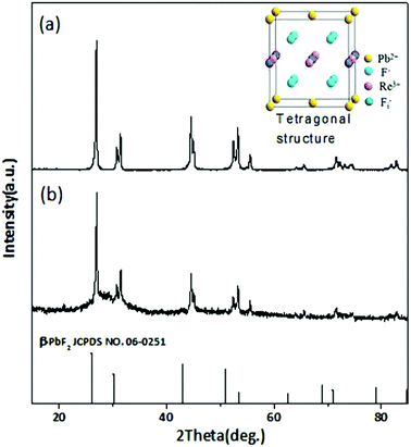
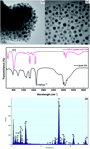
β-PbF2 has a typical cubic fluorite crystal structure. Ln3+ ions were selectively incorporated into β-PbF2 NCs to substitute for lead ions (Pb2+), while the fluoride ion interstitial (Fi−) mechanism provided charge compensation in Ln3+-doped oxyfluoride GCs.28 Based on our previous work,29,30 β-PbF2:Ln3+ NCs exist as two different structures in oxyfluoride GCs, namely, ‘‘pseudo-cubic’’ and tetragonal structures, as induced by different annealing temperatures. In our system, the annealing temperature (440 °C) resulted in a tetragonal structure in β-PbF2:Ln3+ NCs. The crystal structure of the NCs was investigated using XRD, as shown in Fig. 1, by comparison with standard diffraction peaks of β-PbF2. The XRD patterns of the GCs and NCs were similar, indicating that the nanocrystal structure remained unchanged during corrosion. The XRD peak positions of GCs doped with Ln3+ ions had moved towards a higher angle, which indicated shrinkage of the β-PbF2 lattice and confirmed the incorporation of Ln3+ ions into the β-PbF2 NCs.31 Another significant feature was splitting of the main peaks in the XRD pattern, indicating that the NC structure was tetragonal, as shown in the inset of Fig. 1. According to the Bragg diffraction equation and inter-planar spacing equation, we had obtained a tetragonal structure with lattice constants a = b = 0.562 nm and c = 0.587 nm, while the lattice constants of the pseudo-cubic structure were a = b = c = 0.575 nm at the same doping level, but produced using heat treatment at a relatively low temperature.29 Meanwhile, inter-planar spacings, d(hkl), of the tetragonal structure were obtained, including d(111) = 0.329 nm, d(002) = 0.294 nm, and d(020) = 0.281 nm.TEM and HRTEM were performed to unambiguously confirm the precipitation of β-PbF2:Ln3+ NCs in GCs after heat treatment, as shown in Fig. 2(a). Many darker particles were dispersed in the glassy matrix, with average crystal diameters of about 7 nm. The even size of the NCs and their almost uniform morphology implied that the GC silicate matrix had a limiting effect on NC growth. As shown in Fig. 2(b), after corrosion treatment, NCs were released from the silicate glass matrix, while the surface-modification reagent OA prevented NC aggregation, allowing direct observation of the NC nanostructures. NCs in GCs or dispersed in ethanol had similar shapes and sizes, implying that the NCs are released from the silicate glass matrix without damage. The presence of NCs coated successfully with OA was confirmed by the FT-IR spectra (Fig. 3). With OA, bands in the 2840–2970 cm−1 region were attributed to the symmetric and asymmetric stretching of CH2 groups and the terminal CH3 group. respectively. However, the intense peak at 1707 cm−1 due to OA molecules, associated with the C![[double bond, length as m-dash]](https://www.rsc.org/images/entities/char_e001.gif) O bond, disappeared and was replaced with two new peaks at 1458 cm−1 and 1553 cm−1 due to the symmetric and asymmetric stretching vibrations of COO− groups, respectively.32 These observations confirmed that the COOH group of OA had chemically bonded with OH on the surface of the β-PbF2:Ln3+ NCs. Meanwhile, to ensure that the glass matrix was thoroughly corroded and that the nanocrystal components were identified, NCs released from the silicate glass matrix were studied using energy dispersive X-ray spectroscopy (EDS), as shown in Fig. 2(d). The EDS measurements showed that the main nanocrystal components were β-PbF2:Ln3+ NCs, with no trace of Cd2+ ions. Therefore, we concluded that β-PbF2:Ln3+ NCs were completely released from the glass matrix.
O bond, disappeared and was replaced with two new peaks at 1458 cm−1 and 1553 cm−1 due to the symmetric and asymmetric stretching vibrations of COO− groups, respectively.32 These observations confirmed that the COOH group of OA had chemically bonded with OH on the surface of the β-PbF2:Ln3+ NCs. Meanwhile, to ensure that the glass matrix was thoroughly corroded and that the nanocrystal components were identified, NCs released from the silicate glass matrix were studied using energy dispersive X-ray spectroscopy (EDS), as shown in Fig. 2(d). The EDS measurements showed that the main nanocrystal components were β-PbF2:Ln3+ NCs, with no trace of Cd2+ ions. Therefore, we concluded that β-PbF2:Ln3+ NCs were completely released from the glass matrix.
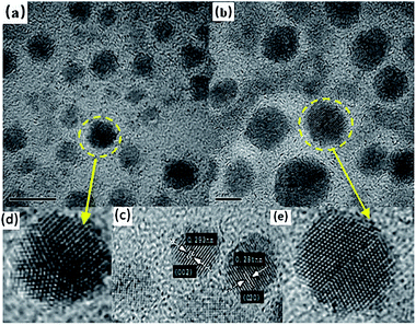 | ||
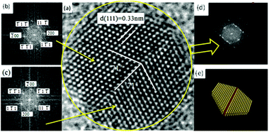
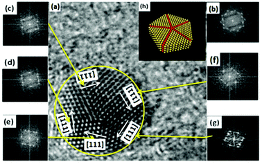
| Fig. 3 (a and d) Five-fold twinned nanocrystals; (b and e) two-fold twinned nanocrystals; (c) interplanar spacing of NCs. | ||
By measuring the inter-planar spacing, we found that tetragonal-structure NCs existed in the sample, which was consistent with the XRD results. Furthermore, twinned NCs were widespread, in addition to single NCs, as shown in Fig. 3(c). If twinning growth plays a dominant role in controlling the nanostructures of NCs in GCs, more twinning structures or twinned NCs should be found in samples. Fig. 3 show the two representative twinning structures of NCs: two-fold twinning and five-fold twinning. As both these twinning nanostructures were fabricated during the same process, they illustrate how NCs grow in GCs.
The projected shape of two-fold twinned NCs (along the [011] direction) was clearly not circular, but more hexagonal. The two-fold twinned NCs consisted of flat {111} and (100) crystal facets, as shown in Fig. 4. A schematic diagram (1![[thin space (1/6-em)]](https://www.rsc.org/images/entities/char_2009.gif) :
:![[thin space (1/6-em)]](https://www.rsc.org/images/entities/char_2009.gif) 1) of the projected shape and facets of the two-fold twinned NCs is shown in Fig. 3(e). For tetrahedral subunits in a pseudo-cubic structure, the angle between adjacent {111} faces is known to be 70.53°, the same as a perfect face-centered cubic (fcc) crystal. However, the angle of the (111) plane was measured as 71 ± 0.3° in the two-fold twinned NCs in our system, which was larger than the angle (70.53°) between adjacent {111} faces in a pseudo-cubic structure. β-PbF2:Ln3+ NCs possesses a tetragonal structure, with the angle between adjacent {111} faces calculated to be 71.06°, which was consistent with our results.
1) of the projected shape and facets of the two-fold twinned NCs is shown in Fig. 3(e). For tetrahedral subunits in a pseudo-cubic structure, the angle between adjacent {111} faces is known to be 70.53°, the same as a perfect face-centered cubic (fcc) crystal. However, the angle of the (111) plane was measured as 71 ± 0.3° in the two-fold twinned NCs in our system, which was larger than the angle (70.53°) between adjacent {111} faces in a pseudo-cubic structure. β-PbF2:Ln3+ NCs possesses a tetragonal structure, with the angle between adjacent {111} faces calculated to be 71.06°, which was consistent with our results.
In five-fold twinned NCs, five tetrahedral units share a common [110] edge as the five-fold symmetry axis, and every unit is twinned with two adjacent units through (111) lattice planes, as shown in Fig. 4. As mentioned above, the angle between adjacent {111} faces was just 71.06° in the tetragonal structure, which differed from 72° by 0.94°. Therefore, forming five-fold twinned crystals in the tetragonal structure resulted in a 4.7° deficiency compared with the pseudo-cubic structure and a perfect fcc structure. A gap of 7.35° can be calculated for the theoretical dihedral angle between two (111) planes of a tetrahedron (70.53°), resulting from an angle difference of 1.47° between every two tetrahedral units in the five-fold twinned crystals with a pseudo-cubic structure (Fig. 5).
As mentioned above, twinned NCs were seldom found in metal fluorides with strong ionicity. We believe that this was due to the strong electrostatic interactions between cations and anions in the metal fluorides with strong ionicity. Anions and cations are always paired, making it difficult to produce ion dislocations in metal fluorides with strong ionicity compared with metallic elements and ionic crystals with weak ionicity. However, the twinned crystals formed in β-PbF2 were closely tied to its special crystal structure. β-PbF2 is a typical fluorite structured crystal in which the F− ion sublattice forms a simple cubic lattice and the Pb2+ ion sublattice forms a fcc lattice similar to some metallic elements. However, β-PbF2 shows an interesting phenomenon called ‘sublattice melting’ at ∼700 K. At this temperature, F− ions undergo ‘sublattice melting’ and leave their sites, while the Pb2+ ion sublattice is stable.33 In our oxyfluoride GCs, β-PbF2:Ln3+ NCs grew at 440 °C (∼710 K), Pb2+ ions formed a rigid cation framework, and F− ions were in a sublattice melting state. Therefore, during β-PbF2:Ln3+ NC crystallization, crystallization of the Pb2+ ion sublattice determines the crystallization characteristics of the β-PbF2 NCs. As Pb2+ ions form a stable fcc sublattice similar to metallic elements, five-fold twinning in β-PbF2:Ln3+ might draw on the analysis methods of metallic elements.
To gain deeper insight into the formation mechanism of twinned β-PbF2 NCs in oxyfluoride GCs and analogous metallic elements, we employed a thermodynamic model for qualitative analysis.2,34,35 The total Gibbs free energies of β-PbF2 NCs are given by eqn (1) and (2), in which, Uc, Us, Ue are the cohesive energy, surface energy, and elastic strain energy, respectively:
| Usingle = Uc +Us = VEC + Sγ | (1) |
| UFivefold = Uc +Us + Ue = VEC + Sγ + VW | (2) |
In the above equations, V, S, EC, γ, and W are the volume, total surface area, crystal cohesive energy per unit volume, specific surface energy, and elastic strain energy density for five-fold twinned NCs, respectively. Considering both single crystals and five-fold twinned crystals to possess the same volume, the difference in free energy between the formation of a single-crystal and five-fold twinned crystal can be described using eqn (3):
| Usingle − UFivefold = ΔSγ − VW | (3) |
Therefore, the competition between crystal elastic strain energy and surface free energy plays a key role in the formation of five-fold twinned NCs. The value of ΔSγ is positive because under same volume conditions, the total surface area of five-fold twinned NCs is smaller than that of single NCs. A smaller VW results in a lower free energy of the five-fold twinned NCs, and five-fold twinned NCs can be formed more easily than single NCs. In our system, the closer the angle between adjacent {111} faces is to 72°, the smaller VW became. Therefore, Ln3+ doping into β-PbF2 favored the formation of five-fold twinned NCs because it induced a change from a pseudo-cubic structure to a tetragonal structure. Meanwhile, a size effect on the particle morphologies of these faceted fcc-Fe NCs has been reported by Ling and coworkers36 using a similar theory, finding that small sizes (5–13 nm) favored five-fold twinned NCs, even perfect icosahedral NCs. In our system, NCs have a spherical morphology of 4–12 nm, with most 7 nm in size, which is just within the range of 5–13 nm. In our system, the NCs were approximately spherical and not faceted37,38 because the NCs were not isolated, but bound tightly by the glass matrix with great viscosity during the NC growth process.
As discussed above, five-fold twinned NCs were widespread in our GCs due to the structure of β-PbF2:Ln3+ transforming into a tetragonal structure, because the tetragonal structure possesses a lower binding energy compared with the pseudo-cubic structure. However, it is still not clear how the Ln3+ ions cause this structural change. In fact, the structural change results from the difference in ionic polarization force between the Pb2+ and Ln3+ ions. The ionic polarization force characterizes the ability to attract charge around an ion, with a stronger ionic polarization force resulting in a greater ability to attract charge.39 In ionic compounds, we generally consider only the polarization force of cations because the polarization force of anions is small enough to be neglected. The polarization force of cations is closely related with the charge number and electron configuration of ions, as described by eqn (4):
 | (4) |
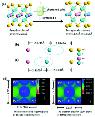
As mentioned above, the structural change from a pseudo-cubic to tetragonal structure was the process of lattice shortening along the A and B axes, and stretching along the C axis, as shown in Fig. 6(a). In the pseudo-cubic structure, the interstitial distance of fluoride ions (Fi−) between Pb2+ was equal to the distance of Fi− ions between Ln3+ ions, while in the tetragonal structure, the distance of Fi− between Pb2+ ions was larger than the distance of Fi− between Ln3+ ions, as shown in Table 1. Therefore, the structural change from a pseudo-cubic to tetragonal structure resulted in Fi− ions becoming closer to Ln3+ ions, but further from Pb2+ ions. By calculation, the polarization power of Pb2+ ions is about 42 Å−1, while those of Yb3+ and Er3+ ions were about 30 Å−1. Therefore, the ability of Pb2+ ions to attract charge is stronger than that of Ln3+ ions. When Ln3+ ions are doped into β-PbF2, a charge balance can be achieved by introducing FI− ions. If the distance of Fi− ions between Pb2+ ions is equal to the distance of Fi− ions between Ln3+ ions, the electron cloud of Fi− ions is inclined toward Pb2+ ions compared with Ln3+ ions, as shown in Fig. 6(b). Fi− ions are used to balance the charge, but the electron cloud of Fi− ions is inclined toward Pb2+, resulting in a local charge imbalance with a Ln3+ centre. Therefore, the pseudo-cubic structure was not the most stable and will slightly change, with shortening along the A and B axes, and stretching along the C axis to form a tetragonal structure. Accordingly, Fi− ions are closer to the Ln3+ ions than Pb2+ ions, and Fi− ions are better at balancing the extra charge of the Ln3+ ions, as shown in Fig. 6(c). To further prove our conjecture, the electron clouds of the pseudo-cubic and tetragonal structures were simulated using ab initio computer simulation methods (using the Cambridge Sequential Total Energy Package module, CASTEP). The Perdew–Burke–Ernzerhof (PBE) generalized gradient approximation (GGA) and Ultrasoft were selected as the exchange-correlation function and pseudo-potential, respectively.43 The simulation result is shown in Fig. 6(d). In the pseudo-cubic structure, the electron cloud of FI− ions tended to be closer to the Pb2+ ions than to Ln3+ ions, while in the tetragonal structure, the opposite was true. This simulation result was consistent with theoretical models established earlier.
| Structure | Lattice constant (Å) | Ion distance (Å) |
|---|---|---|
| Pseudo-cubic structure | a = b = c = 5.75 | Pb2+⋯Fi−, 2.8745 |
| Ln3+⋯Fi−, 2.8745 | ||
| Tetragonal structure | a = b = 5.62 | Pb2+⋯Fi−, 2.9350 |
| c = 5.87 | Ln3+⋯Fi−, 2.8100 |
In summary, Ln3+ doping into β-PbF2 under heat treatment at 440 °C produced β-PbF2:Ln3+ with a tetragonal structure. Consequently, the angle of the (111) plane was 71.06° in the tetragonal structure, which was larger than that in the pseudo-cubic structure. As the angle of the (111) plane was closer to 72°, resulting in a smaller inherent strain, five-fold twinned NCs were easier to form.
Conclusions
In summary, oxyfluoride GCs were prepared in a high-temperature environment and β-PbF2:Ln3+ NCs were released from the glass matrix by etching off the glass matrix. The β-PbF2:Ln3+ NC structure with a narrow crystallite size distribution (mainly 7 nm) was clearly observed and studied. Furthermore, five-fold twinned β-PbF2 NCs in GCs were confirmed to be widespread. Sublattice melting of the F− ion sublattice in β-PbF2 and Ln3+ doping into the β-PbF2 lattice played key roles in the formation of five-fold twinned β-PbF2 NCs with strong ionicity. Competition between Pb2+ and Ln3+ ions for the electron cloud of interstitial fluoride ions (Fi−) was the most important reason for the structural change from a pseudo-cubic to a tetragonal structure. As the angle of the (111) plane in the tetragonal structure was closer to 72° compared with the pseudo-cubic structure, five-fold twinned NCs were easier to form.Increasing attention has been given to studying the growth mechanism of nanocrystals. This work represents a significant advance toward a more comprehensive understanding of the structure of Ln3+ doped β-PbF2 NCs with strong ionicity. This type of twinning growth mechanism might act as a fundamental growth mechanism for many crystals in their initial stage. Controlling the crystal growth process is very important. Such detailed analyses provide basic structural information about twinned NCs that is beneficial for the regulation of nanocrystalline structures and the future fabrication of nanoparticle-based excellent physicochemical properties with great application potential.
Conflicts of interest
There are no conflicts of interest to declare.Acknowledgements
This work was supported by the National Scientific Foundation of China (No. 11574164), 111 Project (No. B07013) and National Science Fund for Talent Training in the Basic Sciences (No. J1103208). The authors would also like to thank Zhou for his work during undergraduate studies and for recommendations provided for the experiments.Notes and references
- S. A. Nepijko, H. Hofmeister and H. Sack-Kongehl, J. Cryst. Growth, 2000, 213, 129–134 CrossRef CAS.
- S. X. Bao, J. W. Zhang, Z. Y. Jiang, X. Zhou and Z. X. Xie, J. Phys. Chem. Lett., 2013, 4, 3440–3444 CrossRef CAS.
- A. X. Yin, X. Q. Min, W. Zhu, H. S. Wu, Y. W. Zhang and C. H. Yan, Chem. Commun., 2012, 48, 543–545 RSC.
- Y. Wu, Q. Chen, M. Takeguchi and K. Furuya, Surf. Sci., 2000, 462, 203–210 CrossRef CAS.
- A. Ojha, H. Sehitoglu, L. Patriarca and H. J. Maier, Philos. Mag., 2014, 94, 1816–1817 CrossRef CAS.
- B. Lim, Y. J. Xiong and Y. N. Xia, Angew. Chem., Int. Ed., 2007, 46, 9279–9282 CrossRef CAS.
- M. Rappaz and G. Krtuldu, JOM, 2015, 67, 1812–1820 CrossRef CAS.
- M. Kim, H. J. Park, S. W. Han, J. Park and W. S. Yun, Bull. Korean Chem. Soc., 2013, 34, 2243 CrossRef CAS.
- B. Wiley, Y. G. Sun and Y. N. Xia, Acc. Chem. Res., 2007, 40, 1067–1076 CrossRef CAS PubMed.
- H. Hofmeister, Encycl. Nanosci. Nanotechnol., 2004, 3, 431–452 CAS.
- R. H. Li, S. Lu, D. Y. Kim, S. Schönecker, J. J. Zhao, S. K. Kwon and L. Vitos, J. Phys.: Condens. Matter, 2016, 28, 395001–395010 CrossRef PubMed.
- K. J. M. Bishop, C. E. Wilmer, S. Soh and B. A. Grzybowski, Small, 2009, 5, 1600–1630 CrossRef CAS PubMed.
- Z. R. Dai, S. H. Sun and Z. L. Wang, Nano Lett., 2001, 1, 443–447 CrossRef CAS.
- H. Hubert, B. Devouard, L. A. J. Garvie, M. O'Keeffe, P. R. Buseck, W. T. Petuskey and P. F. McMillan, Nature, 1998, 391, 376–378 CrossRef.
- J. J. Chen, Y. Pan and R. B. Wu, Phys. E, 2010, 42, 2335–2340 CrossRef CAS.
- B. Devouard, M. Posfai, X. Hua, D. A. Bazylinski, R. B. Frankel and P. R. Buseck, Am. Mineral., 1998, 83, 1387–1398 CrossRef CAS.
- K. H. Kuo, Struct. Chem., 2002, 13, 221–229 CrossRef CAS.
- Y. Q. Wang, R. Smirani and G. G. Ross, Nano Lett., 2004, 4, 2041–2045 CrossRef CAS.
- M. Mertier, A. Monterille, G. Patriarche, G. Maze and F. Auzel, Opt. Mater., 2000, 16, 255–267 CrossRef.
- J. Fu, J. M. Parker, P. S. Flower and R. M. Brown, Mater. Res. Bull., 2002, 37, 1843–1849 CrossRef CAS.
- R. P. Fogaca de Almeida, C. Bocker and C. Russel, Chem. Mater., 2008, 20, 5916–5921 CrossRef.
- S. Bhattacharyya, C. Bocker, T. Heil, J. R. Jinschek, T. Hoche, C. Russel and H. Kohl, Nano Lett., 2009, 9, 2493–2496 CrossRef CAS PubMed.
- Y. H. Wang and J. Ohwaki, Appl. Phys. Lett., 1993, 63, 3268–3270 CrossRef CAS.
- C. G. Lin, L. G. Li, S. X. Dai, C. Liu, Z. Y. Zhao, C. Bocker and C. Rüssel, J. Phys. Chem. C, 2016, 120, 4556–4563 CrossRef CAS.
- J. Labéguerie, G. Dantelle, P. Gredin and M. Mortier, J. Alloys Compd., 2008, 451, 563–566 CrossRef.
- S. Haas and A. Hoell, Phys. Rev. B: Condens. Matter Mater. Phys., 2010, 81, 184207–184211 CrossRef.
- A. de Pablos-Martín, F. Muñoz, G. C. Mather, C. Patzig, S. Bhattacharyya, J. R. Jinschek, Th. Höche, A. Durán and M. J. Pascual, CrystEngComm, 2013, 15, 10323–10330 RSC.
- M. Beggioraa, I. M. Reaney and M. S. Islam, Appl. Phys. Lett., 2003, 83, 467–469 CrossRef.
- N. Hu, H. Yu, M. Zhang, P. Zhang, Y. Z. Wang and L. J. Zhao, Phys. Chem. Chem. Phys., 2011, 13, 1499–1505 RSC.
- J. Ge, L. J. Zhao, H. Guo, Z. J. Lan, L. F. Chang, Y. M. Li and H. Yu, Phys. Chem. Chem. Phys., 2013, 15, 17281–17286 RSC.
- V. K. Tikhomirov, D. Furniss and A. B. Seddon, Appl. Phys. Lett., 2002, 81, 1939 CrossRef.
- N. H. Park, Y. F. Wang, W. S. Seo, F. Dang, C. L. Wan and K. Koumoto, CrystEngComm, 2013, 15, 679 RSC.
- E. Cadelanoa and G. Cappellini, Eur. Phys. J. B, 2011, 81, 115–120 CrossRef.
- P. Thangadurai, S. Ramasamy and R. Kesavamoorthy, J. Phys.: Condens. Matter, 2005, 17, 863–874 CrossRef CAS.
- Z. Q. Niu, Q. Peng, M. Gong, H. P. Rong and Y. D. Li, Angew. Chem., 2011, 123, 6439–6443 CrossRef.
- T. Ling, J. Zhu, H. M. Yu and L. Xie, J. Phys. Chem. C, 2009, 113, 9450–9453 CrossRef CAS.
- A. R. Tao, S. Habas and P. D. Yang, Small, 2008, 4, 310–325 CrossRef CAS.
- N. Almora-Barrios, G. Novell-Leruth, P. Whiting, L. M. Liz-Marzán and N. López, Nano Lett., 2014, 14, 871–875 CrossRef CAS.
- K. Fajans, Struct. Bonding, 1967, 3, 88–105 CrossRef CAS.
- J. R. Tessmant, A. H. Kahn and W. Shocklky, Phys. Rev., 1953, 92, 890–895 CrossRef.
- G. Burns, J. Chem. Phys., 1964, 41, 1521 CrossRef CAS.
- G. H. Cartledge, J. Am. Chem. Soc., 1930, 52, 3066 CrossRef.
- M. D. Segall, P. J. D. Lindan, M. J. Probert, C. J. Pickard, P. JHasnip, S. J. Clark and M. C. Payne, J. Phys.: Condens. Matter, 2002, 14, 2717–2744 CrossRef CAS.
| This journal is © The Royal Society of Chemistry 2018 |

