 Open Access Article
Recent developments in polymeric electrospun nanofibrous membranes for seawater desalination
Mantsopa Koena Selatileab,
Suprakas Sinha Ray *ac,
Vincent Ojijoa and
Rotimi Sadikub
aDST-CSIR National Centre for Nanostructured Materials, Council for Scientific and Industrial Research, Pretoria 0001, South Africa. E-mail: rsuprakas@csir.co.za; ssinharay@uj.ac.za
bDivision of Polymer Technology, Department of Chemical, Metallurgical and Materials Engineering, Tshwane University of Technology, South Africa
cDepartment of Applied Chemistry, University of Johannesburg, Doornfontein 2028, Johannesburg, South Africa
First published on 12th November 2018
Abstract
Seawater desalination is a promising strategy that offers an abundant and reliable source of clean fresh water. Nanotechnology, in terms of nanoparticles or electrospun nanofibrous membranes, for water-treatment or desalination applications, is a new concept that has rapidly grown in interest as a method for improving performance by enhancing the surface properties of membranes. Here, we report a critical review on recent developments in membrane-fabrication methods for seawater desalination technologies, focusing mainly on the electrospinning technique. High-performance membranes that address ongoing permeability concerns, while maintaining membrane selectivity, need further study and development. Considering that the world today is faced with energy-shortage crises, these membranes also need to be energy efficient. As electrospinning is considered to be a feasible method for the production of desalination membranes, this technique requires appropriate optimization and the structural properties of the membranes produced need to be controlled in order to tailor their properties to those desired for well-known desalination technologies, such as reverse osmosis and membrane distillation. Moreover, there is a need to understand the influence of membrane structure on performance, and the latest trends in their use as high-performance desalination membranes.
1. Introduction
Clean water is a vital resource for human consumption and agriculture, as well as feed water for industrial processes, which are the most common daily activities that exploit what is arguably the most valuable global resource. However, due to factors such as global warming (since climate change affects the hydrologic cycle), industrialization, and freshwater contamination, among others, existing water sources such as surface water (rivers and dams), recycled wastewater, and some underground sources, are also becoming depleted owing to rising demand and decreasing rainfall for freshwater supply. Wastewater recycling is also unable to meet demand, depending on the extent or severity of contamination. Although several measures that relieve water-supply stresses exist, such as water conservation, infrastructure repair, and improved catchment and distribution systems, they need to be augmented accordingly. The water crisis facing the world today, which affects economic growth and human health, has led to alternative means for obtaining fresh water. The oceans are the Earth's largest available source of water and account for 97% of the available water; they represent a more reliable source of water because they are unaffected by changing rainfall patterns. The remaining 3% is freshwater, of which two thirds is frozen in glaciers and polar ice caps, and the rest is found in underground water reservoirs.1,2 With this in mind, seawater treatment represents a more-reliable approach that has catalyzed research into alternative technologies; as a result, seawater desalination is a popular field of interest. Desalination can be performed on inland underground brackish water or seawater, of which brackish-water treatment is less feasible than seawater treatment. Seawater desalination offers an abundant, steady supply of high-quality water. The desalination of seawater is commonly used in arid regions and deserts, but due to worldwide water stresses has become more popular in developing counties in recent years.3 Desalination involves the evaporation of seawater, thereby removing salts, minerals, and other impurities, to produce fresh water for domestic and industrial use.4The high salt content of seawater makes it unfit for consumption and, at the same time, makes desalination a costly process. The salinity or salt content of seawater is due to the presence of about 3.5% NaCl, which is equivalent to 35 g L−1 or 35![[thin space (1/6-em)]](https://www.rsc.org/images/entities/char_2009.gif) 000 ppm. Drinking water should have a NaCl concentration of less than 280 ppm.3,5 Seawater-desalination methods are classified into thermal, mechanical, electrical, and chemical-energy processes. Desalination technologies are either thermally or pressure driven and include a variety of technologies, such as multi-stage flash (MSF) distillation, multi-effect distillation (MED), mechanical vapor-pressure-compression (MVC) distillation, membrane distillation (MD), reverse osmosis (RO), electrodialysis (ED), and nanofiltration (NF) processes. Thermally based techniques are first-generation technologies, while membrane-based methods are second-generation. Membrane-based methods make use of nanotechnology and membrane science, are more suitable for desalination, and are more economical due to lower energy requirements. These methods include microfiltration, (MF), ultrafiltration (UF), engineered osmosis (EO) (reverse and forward osmosis), and membrane distillation (MD). Reverse osmosis (RO) is the most preferred pressure-driven process, while membrane distillation (MD) is the most preferred thermally driven process. Therefore both RO and MD methods have been intensively researched due to their high salt-removal efficiencies (i.e., >98% NaCl removal) and, as a consequence, are the most used seawater-desalination techniques for the production of drinking water. Other methods, such as nanofiltration, are mainly employed for lower salt-content removal (20–80% NaCl removal) and mostly for brackish water.6–9 Desalination has become more practical and economical, and research into membrane-based desalination methods has gradually grown over the past ten years (Fig. 1).
000 ppm. Drinking water should have a NaCl concentration of less than 280 ppm.3,5 Seawater-desalination methods are classified into thermal, mechanical, electrical, and chemical-energy processes. Desalination technologies are either thermally or pressure driven and include a variety of technologies, such as multi-stage flash (MSF) distillation, multi-effect distillation (MED), mechanical vapor-pressure-compression (MVC) distillation, membrane distillation (MD), reverse osmosis (RO), electrodialysis (ED), and nanofiltration (NF) processes. Thermally based techniques are first-generation technologies, while membrane-based methods are second-generation. Membrane-based methods make use of nanotechnology and membrane science, are more suitable for desalination, and are more economical due to lower energy requirements. These methods include microfiltration, (MF), ultrafiltration (UF), engineered osmosis (EO) (reverse and forward osmosis), and membrane distillation (MD). Reverse osmosis (RO) is the most preferred pressure-driven process, while membrane distillation (MD) is the most preferred thermally driven process. Therefore both RO and MD methods have been intensively researched due to their high salt-removal efficiencies (i.e., >98% NaCl removal) and, as a consequence, are the most used seawater-desalination techniques for the production of drinking water. Other methods, such as nanofiltration, are mainly employed for lower salt-content removal (20–80% NaCl removal) and mostly for brackish water.6–9 Desalination has become more practical and economical, and research into membrane-based desalination methods has gradually grown over the past ten years (Fig. 1).
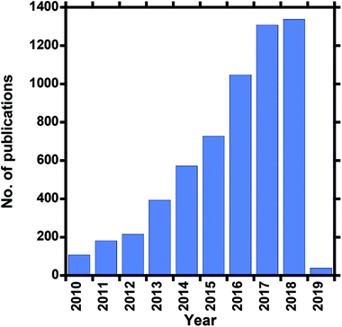 | ||
| Fig. 1 Number of publications over the past ten years that involve electrospun desalination membranes (Scopus search, 05 October 2018). | ||
The process performance of membrane-based desalination methods, in terms of permeability (water flux) and separation (selectivity or salt rejection), depends highly on the characteristics of the membrane. With continuous improvements achieved through the optimization of membrane characteristics, membrane processes are becoming more performance efficient (e.g., improved permeability) and, as a consequence, use less energy than thermally driven processes.
Nanofibrous membranes produced by electrospinning (ENMs) form part of the nanotechnology-based methods used to fabricate novel separation membranes. ENMs possess exceptional features because they can be used to produce multi-functional water-purification materials. However, for desalination purposes, their highly porous structures with broad pore-size distributions (micron-sized pores) limit their ability to reject dissolved salts, such as NaCl, from water. They are therefore limited to MF-separation applications involving large/micro-sized particles, or as pre-filters prior to delicate RO processes. Through modification, the water-treatment applications of these membranes can be further extended to the removal of more-complex colloidal solutions, such as oil/water suspensions, which involves the rejection of an organic solute. Modification of an ENM surface with a thin selective coating layer through crosslinking results in the formation of a composite membrane with smaller pores that can be used for UF separations. Further modification through interfacial-polymerization coating leads to nonporous composite membranes that can be used in NF and RO applications. Interfacial polymerization produces a polyamide coating as an ultrathin top selective layer on the ENM surface, resulting in a thin-film nanofibrous composite (TFNC) membrane; such a membrane can be used in RO and MD separations, which are two commonly used desalination methods. The coated layer of a TFNC membrane can be further modified to improve permeability and salt rejection (permselectivity) through the inclusion of nanoparticles (NPs). The incorporation of NPs into ENMs help to enhance performance (both flux and salt rejection); therefore, the use of nanotechnology in existing desalination technologies can result in high membrane performance. This review article examines the development of polymeric ENMs for seawater desalination processes, particularly RO and MD, which are the most commonly used and most efficient methods. The influences of membrane structure on performance, and the latest trends in their use as high-performance desalination membranes, are also discussed.
2. Water treatment by membrane-based technologies and materials used
Membrane separation is a technology that selectively separates materials using the pores of a membrane that acts as a physical barrier. The semi-permeable membrane allows water to pass through the membrane while retaining solute particles through sieving and diffusion mechanisms. The pressure applied on the feed side of the membrane serves as the driving force that separates water into two streams, namely the permeate (purified water) and the retentate (rejected concentrated salt solution), which is brine in a desalination process. Membrane technologies are classified according to separation principles or driving force, and membrane properties (e.g., pore size, permeability, and selectivity). Pressure-driven membrane-based processes are classified according to membrane pore size and their corresponding solute particle sizes, namely: microfiltration (MF) > ultrafiltration (UF) > nanofiltration (NF) > reverse osmosis (RO), with the larger pore/particle sizes used for MF and the smallest for RO (Fig. 2). The required applied pressure (trans-membrane pressure) differs according to the filtration process, and increases with decreasing membrane-pore size. Consequently, RO operates at the highest hydrostatic pressure.10,11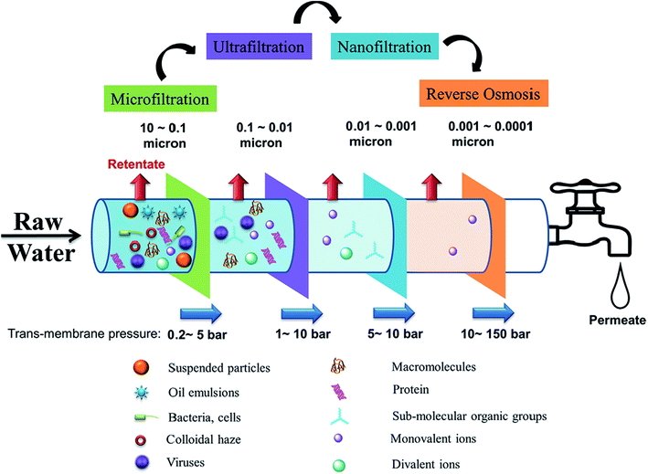 | ||
| Fig. 2 Pressure-driven membrane processes for water treatment technologies, showing the particles effectively captured by each process along with the pore sizes of the membranes used for each process. Reproduced with permission from ref. 10. Copyright 2018, Elsevier Science Ltd. | ||
2.1. Pressure-driven processes and the role of the ENM
 | ||
| Fig. 3 Cross-sections of (a) the mid layer of a TFC UF membrane prepared by the phase-inversion method, (b) a phase-inversion mid layer coated with a thin selective layer (cross-linked or grafted), and (c) an ENM mid layer coated with a thin film (TFNC). Reproduced with permission from ref. 17. Copyright 2006, Elsevier Science Ltd. | ||
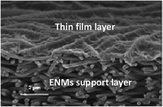 | ||
| Fig. 4 A NF TFNC membrane. Reproduced with permission from ref. 10. Copyright 2018, Elsevier Science Ltd. | ||
2.2. Thermally driven membrane processes
Thermally driven membrane processes are evaporative desalination techniques in which energy is used to heat water, which then evaporates and condenses into clean purified water. As this is a rather energy-intensive process, it is more viable in refineries or power plants where waste heat is used as the heat source. Nevertheless, membrane distillation (MD) operates at a lower temperature than a typical thermal-desalination process, and at a lower hydrostatic pressure than RO. As the name implies, it combined membrane-based and thermally based desalination processes. MD is a thermally driven non-isothermal process that makes use of a microporous hydrophobic membrane as a barrier (for water as the liquid phase), and only allows the water-vapor phase to pass through. Vapor molecules permeate through the membrane from the warmer high-vapor-pressure side to the cooler low-vapor-pressure side. It is an MF process with membrane pore sizes in the microfiltration range (0.1–1 μm) and is driven by the partial vapor-pressure difference across a microporous hydrophobic membrane (which is induced by the temperature difference between the feed side and the permeate side) produced by phase inversion (PVDF, PP, and PTFE capillary/flat-sheet types), which are now as conventional as ENMs.20,21Membrane distillation is a promising desalination technology that was developed following the evolution of RO. It is also regarded to be a third-generation desalination technique.22 MD addresses some of the limitations of RO, such as brine concentration, in order to maximize water recovery (salt rejection) at high fluxes. The high rejection of non-volatile components and the use of lower energy than RO and conventional distillation processes make MD an attractive separation method, as it offers more advantages over other desalination technologies. MD does not require any transmembrane hydrostatic pressure and therefore self-sustained or single-layer ENMs that do not require thin-film coatings can be used. However, it is worth noting that hydraulic pressure is required, but at levels far less than those used in pressure-driven processes, such as RO.5 MD is widely used for industrial water desalination in a variety of industries, including brackish and seawater desalination, RO-brine treatment, resource recovery, wastewater reuse, and the treatment of mine water and radioactive waste, among others.
MD can be configured in four ways: direct-contact membrane distillation (DCMD), air-gap membrane distillation (AGMD), sweeping-gas membrane distillation (SGMD), and vacuum membrane distillation (VMD), which are determined by the manner in which the vapor-pressure gradient across the membrane arises, as summarized in Fig. 5.3,10,23
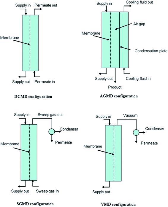 | ||
| Fig. 5 Depicting various MD configurations. Reproduced with permission from ref. 23. Copyright 2006, Elsevier Science Ltd. | ||
Direct-contact membrane distillation (DCMD) is the most popular due to its simple set-up and fabrication process; the feed directly contacts the hot side of the membrane surface. Volatile water molecules evaporate at the liquid/vapor interface at the high-temperature-feed side, then cross through the hydrophobic porous membrane, and finally condense at the cold permeate-side of the membrane. This process requires low operating temperatures as the water boils at 30–80 °C, which is below its boiling point at atmospheric pressure.10,24 The feed is only in direct contact with the hot side of the membrane surface in air-gap membrane distillation (AGMD), due to stationary air present between the membrane and the condensation surface. This method is operated using a membrane and an air gap through which the water vapor permeates. The warm water feed and the cooling water create a temperature difference between the two sections. A typical example is the 25 to 83 °C temperature gradient used during AGMD with an electrospun PVDF. Sweeping-gas membrane distillation (SGMD) uses an inert gas to sweep the vapor at the permeate side of the membrane such that it condenses on the outside of the membrane module. A moving gas barrier, as in AGMD, is used to reduce heat loss and to enhance the mass-transfer coefficient. Vacuum membrane distillation (VMD) uses a pump to create a vacuum on the permeate side of the membrane.3,8
3. Membrane fabrication by electrospinning
The membrane-fabrication technique is highly important as it directly affects the properties of the membrane as well as its water-desalination performance. Amongst popular techniques used to fabricate polymeric desalination membranes (phase inversion, interfacial polymerization, stretching, and track etching), electrospinning offers a number of advantages, including control over nanofiber morphology, which leads to membranes with the desired properties. Some of the unique characteristics of electrospun membranes include nano-dimensional fibers, high specific surface areas, high porosities, and highly oriented or aligned nanofibers, which benefit the nanofiber-based construction significantly. The surface and structural properties of a membrane, such as its thickness, porosity, pore-size distribution, polymer crystallinity, and hydrophobicity/hydrophilicity, are all affected by fiber diameter and morphology, which can also be controlled by the electrospinning parameters, namely polymer-solution concentration or viscosity, conductivity, voltage, and flow rate.12,25Electrospinning involves uniaxial stretching of viscoelastic polymer solution by repulsive electrostatic forces under electric field, and is fundamentally governed by a number of operating conditions and solution properties.26 It all starts with a high molecular weight polymer that dissolves in a suitable solvent to form a homogeneous solution with sufficient chain entanglements. The solution properties are dependent on the solvent and polymer itself and the selection of the operating conditions for a sufficiently high polymer chain entanglement solution, through parameter optimization results in the production of continuous network of fibers. One of the advantages of electrospinning is that it allows for easy tuning of parameters in order to obtain the fibres with desired physical properties and performance.27
Electrospinning consists of three basic components, namely: high voltage supply, syringe connected to a needle and a metal collector (Fig. 6). The syringe, containing the polymer solution with a blunt needle tip (spinneret) is connected as a positive electrode. This passes charges to the polymer solution droplet suspended at the tip. The collector offers a platform for deposition of fine micro/nanosized fibers and can either be grounded or carry a charge opposite to the spinneret, most often, negative charge. At the initial stages of the process, the polymer solution in the syringe is pushed to the needle tip and remains suspended. Surface tension keeps the round hemispherical droplet attached to the needle tip. Once the voltage is increased, the hemispherical droplet elongates into a conical shape and forms a Taylor cone, as soon as the voltage reaches a critical value. As the high voltage source creates an electrical field between the spinneret and the collector, the polymer solution droplet at the needle tip will then undergo stretching and thinning into a fluid jet, as it travels towards the collector, followed by deposition onto the collector in the form of fibers.28 For each application, the nanofibers need to possess certain structural characteristics, thus for desalination, properties such as fiber diameter, morphology and membrane pore features are critical and they can easily be controlled by the tuning of electrospinning parameters.
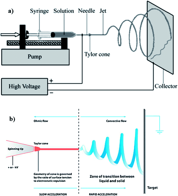 | ||
| Fig. 6 Typical electrospinning set up showing (a) the basic components, and (b) the ohmic/convective flows regions of the jet flight. Reproduced with permission from ref. 28. Copyright 2010, Elsevier Science Ltd. | ||
In electrospinning, process optimisation is the first step for nanofiber production. Process optimization entails the selection of the appropriate polymer–solvent properties and process conditions in order to control the desired physical properties, such as fibre diameter, morphology, and mechanical strength of the resulting nanofibers.29
The selection of the polymer is the first step in the optimisation procedure and this depends mostly on the end application of the resulting nanofibrous membranes. For electrospinning of polymers, high molecular weight polymers are always preferred as they give enough chain entanglement during stretching of a polymer jet, which helps to minimise the formation of beaded nanofibers. The most common electrospun polymers for water-treatment use are PVDF, polysulfone (PSU), and cellulose acetate (CA).3,10
Solvents that readily dissolve the polymer without the need to be heated are highly preferred. A good solvent needs to have good conductivity, less surface tension, and sufficiently volatile. This facilitates fibre drying in order to avoid wet and defect free fibres deposited onto the collector. Solvents with boiling points that are too low will cause constant clogging of the needle due to rapid solvent evaporation (premature drying), while those with high boiling point will hinder fiber drying after reaching the collector, thereby resulting in wet fibers. A mixture of solvents, such as a binary solvent system is used to combine properties as a way of adding good properties of one solvent or to suppress the undesirable properties of the other solvent. For example, a chosen solvent may have poor conductivity and high volatility and therefore can be blended with a solvent that has better conductivity and low volatility. The volatility of a solvent is important as it will determine the rate of evaporation of polymer solution as the polymer jet travels toward the collector and deposited as nanofibers. Solvent evaporation is one of the main contributors towards porous fiber morphology, just like relative humidity. Although, not all solvents with low surface tension are good for electrospinning, a solvent with high conductivity and low surface tension are mostly suitable for any polymer–solvent system.28 Such solvents offer high coulombic forces responsible for facilitating stretching of the polymer jet. Therefore, the surface tension can be overcome at a low voltage.
Different solvents have different surface tensions.28 Surface tension favors the formation of beaded fibers, because it offers resistant to the flow of polymer solution and stretching of a jet. The electrostatic force supplied by the applied voltage should overcome the surface tension for the jet to initiate. Usually, solvents with high surface tension are blended with those of lower surface tension and higher conductivity in order to adjust/suppress the overall surface tension of the solution.
A polymer solution is either conductive or dielectric. A dielectric polymer solution requires sufficient voltage to form a Taylor cone and initiate electrospinning and jet formation as only few charges are available in solution. A conductive polymer solution on the other hand, requires lesser critical voltage to initiate electrospinning, due to the availability of more free charges in the solution that are responsible for forming a Taylor cone.28 Solvents with good conductivity have high dielectric constant and this promotes high repulsive Coulomb forces (electric charge), thereby inducing stretching of a polymer jet.28 Studies show that the jet radius is inversely proportional to the cube root of the electrical conductivity, hence an increase in conductivity leads to a decrease in the fiber diameter.28 On the other hand, low conductivity causes weak electrical force (fewer ions), thereby resulting in insufficient elongation of jet and formation of beads due to jet break-up, forming droplets rather than fibers. Conductivity can also be enhanced by the addition of ionic salts to give finer, uniform and bead-free fibers.28
Viscosity of a polymer solution is directly proportional to the polymer solution concentration and molecular weight, i.e., number of chain entanglements among the polymer chains (ne). This affects the degree of interaction between polymer chains and solvent and the polymer structure.30 Increase in concentration results in an increase in chain entanglement. Similarly, solution containing higher molecular weight polymer results in higher chain entanglement, add higher viscosity, when compared to one with the same concentration but lower molecular weight polymer. There is lack of continuous fiber formation at low viscosity, while high viscosity solutions are difficult to electrospin. Low viscosities offer high resistance to the formation of continuous fibers and to the elongation of polymer jet from the syringe,31 hence the formation of beads. Other factors that will affect the viscosity of a polymer solution (at the same concentration) are solvent ratios, temperature, and additives. Fig. 7 reports the polylactide (PLA) solution concentration dependence of fiber morphology.
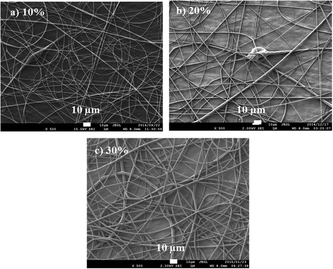 | ||
| Fig. 7 Fibers produced from PLA solution concentrations of 10, 12, and 15 wt/vol% spun at 20 kV and 15 cm (spinning distance), and at a flow rate of 10 μL min−1. | ||
The electric field created between the syringe needle tip and the collector induces charges onto the polymer solution droplet to form a Taylor cone. The charges are then transferred to the jet ejected from the needle and attracted to the collector, once the critical voltage has been reached. The critical voltage varies for each polymer–solvent system. High voltage increases the repulsive forces of fluid jet as more charges are introduced, which leads to increased pulling force and therefore, thin fibers are formed. The influence of voltage on fiber diameter is however, dependent on the solution concentration and spinning distance. As such, increase in fiber diameter with increase in voltage has also been reported.30,32 This can be due to a number of factors: (i) an increased pulling of polymer solution volume out of a needle, although at a constant flowrate,33 (ii) an increase in the length of jet, which will in turn reduce the distance for whipping region (i.e., the convective flow region in Fig. 6(b)) responsible for further jet elongation and fiber diameter reduction, and (iii) slow jet flight because of weak acceleration of jet to the collector.34 There is also more solvent evaporation as the voltage increases.35 The reduction of fiber diameter continues until a critical voltage is reached, beyond which is the likelihood of bead formation. Optimization of voltage in order to obtain a stable Taylor cone is mainly a balance between the voltage, distance, and the flow rate. Low flow rates require low applied voltages, while high applied voltages are required when high flow rates are used. The effects of voltage and spinning distance on the fibre diameter were studied by using a 12 wt/vol% PLA solution in 30![[thin space (1/6-em)]](https://www.rsc.org/images/entities/char_2009.gif) :
:![[thin space (1/6-em)]](https://www.rsc.org/images/entities/char_2009.gif) 70 DCM
70 DCM![[thin space (1/6-em)]](https://www.rsc.org/images/entities/char_2009.gif) :
:![[thin space (1/6-em)]](https://www.rsc.org/images/entities/char_2009.gif) TFE. Voltages of 10, 15, 20, and 25 kV were tested with spinning distances of 10, 12.5, and 15 cm. The flow rate was maintained at 10 μL min−1. Fig. 8 reports the SEM images illustrating the effect of spinning distance and voltage difference on fiber diameter.
TFE. Voltages of 10, 15, 20, and 25 kV were tested with spinning distances of 10, 12.5, and 15 cm. The flow rate was maintained at 10 μL min−1. Fig. 8 reports the SEM images illustrating the effect of spinning distance and voltage difference on fiber diameter.
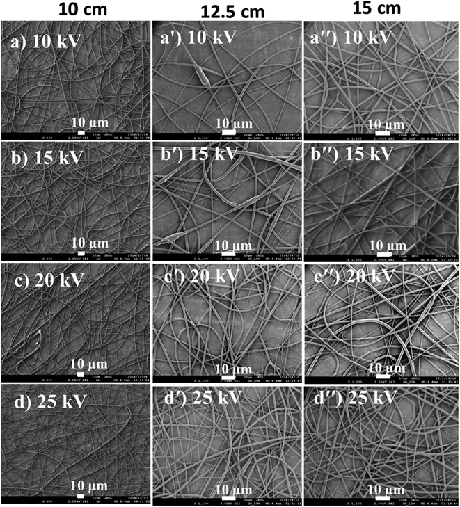 | ||
Fig. 8 PLA fibers spun from 12% PLA/(30![[thin space (1/6-em)]](https://www.rsc.org/images/entities/char_2009.gif) : :![[thin space (1/6-em)]](https://www.rsc.org/images/entities/char_2009.gif) 70 DCM/TFE) solution at distances of 10, 12.5 and 15 cm and voltages of 10, 15, 20 and 25 kV. 70 DCM/TFE) solution at distances of 10, 12.5 and 15 cm and voltages of 10, 15, 20 and 25 kV. | ||
The spinning distance affects, directly the jet flight time, whipping distance and the voltage intensity. A short distance intensifies the electric field strength of the voltage and also results in a short jet flight. Spinning distance also controls the fiber diameter, morphology and bead formation. There should to be an optimum distance to allow for the solvent evaporation (fiber drying). Long or sufficient distances will result in bead-free and thin fibers.28,30
The rate of flow affects the rate at which the polymer solution is transferred from the syringe. For every flow rate, there is an optimum voltage to maintain a stable Taylor cone and jet (at a particular distance). An optimum flow rate maintains a balance between the polymer solution, leaving the needle, and the new volume being pumped.30 The balance of flow rate and pulling force of voltage determines the fiber diameter, porosity and geometry of fibers and the shape of Taylor cone. High flow rates are associated with large Taylor cone, resulting in large diameters and pore size (Fig. 9).
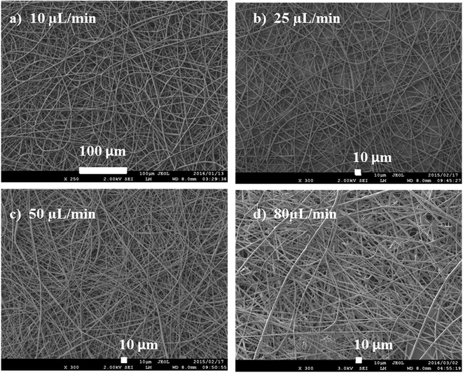 | ||
| Fig. 9 Fibres spun using from a 15 wt/vol% solution at flow rates of (a) 10, (b) 25, (c) 50, and (d) 80 μL min−1. | ||
The flow rate was varied from 10 to 80 μL min−1 in order to study its effect on fibre diameter. As shown in Fig. 9, the smallest fibre diameters were obtained at 10 μL min−1, while the highest flow rates gave the largest diameters. As the flow rate increases (at constant voltage), more of the polymer solution is pulled from the needle, hence, resulting in thicker fibres. Increasing the flowrate leads to a bigger Taylor cone, and a longer, thicker jet. A longer jet produces a smaller whipping region, thereby limiting its further elongation and producing thicker fibres.
The ambient conditions mainly refer to temperature and relative humidity. Humidity affects fiber drying at the collector and this is dependent on the type of polymer–solvent system. For water soluble polymers, e.g., poly(ethylene oxide), poly(vinyl alcohol), etc., fiber diameter reduction, with an increase in humidity, is common. The reason being the fiber solidifying mechanism process, depending on the type of polymer.30 For binary solvent system, small circular pores in the fibers are likely to form in more humid conditions by a process called phase separation, when the more volatile solvent evaporates and followed by condensation during cooling. High humidity causes enlarged pores with high pore density. Low humidity has negative effects on the evaporation rate of the solvent and also causes clogging.35
As a conclusion, it is imperative that a stable Taylor cone is maintained once the optimum conditions for electrospinning are obtained, to ensure continuous and uninterrupted electrospinning.36 However, this remains a challenge for readily clogging polymer–solvent systems, where very highly volatile solvents, e.g., DCM are concerned.37 Through optimization, other factors, such as fibre diameter, can also be carefully controlled. The fiber diameter determines the resulting nanofibrous membrane properties, such as porosity, pore size, surface area, packing density and mechanical properties, which are vital for the end-use performance, such as water filtration applications.
4. Electrospun polymeric nanofibrous membranes (ENMs) in desalination: reverse osmosis (RO) and membrane distillation (MD)
Electrospun nanofibrous membranes are among emerging technologies for water treatment, due to advantages that include their abilities to produce high-quality water and, in most cases, with the consumption of less energy. They are therefore being developed into more functional membranes to meet most water treatment processes, particularly desalination.38 Nanofibers form a significant family of nanomaterials, and their use in the fabrication of novel composite membranes has evidently facilitated improvements in desalination performance.4.1. Water flux
Also known as permeate flux; water flux can be optimized by tuning the electrospinning parameters. Low flux is often the result of low permeability, which results in membrane-surface fouling.39 The water flux (J) is calculated as follows:40
 | (1) |
4.2. Salt rejection
Unlike particle filtration, the separation of dissolved salts (monovalent NaCl) is a very complex process, and the ENM separation efficiency for such salts depends highly on the sizes of the membrane pores, which are primarily controlled by the fiber diameter through a direct relationship:8,40
 | (2) |
4.3 The use of ENMs in reverse osmosis
Electrospun membranes (ENMs), on their own, are too porous to retain salt ions, as their pores are mostly larger than 100 nm and are distributed broadly; they are designed to operate on the microfiltration scale and are therefore suitable for MF separation when directly used (e.g., as pre-filters). Although highly permeable, their solute rejections are too low and they are also highly susceptible to fouling. However, ENMs can be applied to UF when further modified by a thin-film coating (by grafting or casting), and to NF or RO when coated through crosslinking or interfacial polymerization.41 Coating ENMs with thin-film layers is a hierarchical design strategy aimed at improving the functionalities and broadening the separation proficiencies of these membranes, thereby also improving their suitability for more-delicate separation processes, such as NF and RO. ENMs therefore require thin-film top coatings, which led to the development of TFNC membranes by grafting, crosslinking, or interfacial polymerization; ENMs are most commonly transformed into TFNC membranes by surface modification.42–45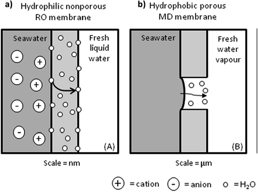 | ||
| Fig. 10 Transport mechanisms of a permeate through: (a) a nonporous TFC RO membrane and (b) a microporous MD membrane. Reproduced with permission from ref. 47. Copyright 2012, Elsevier Science Ltd. | ||
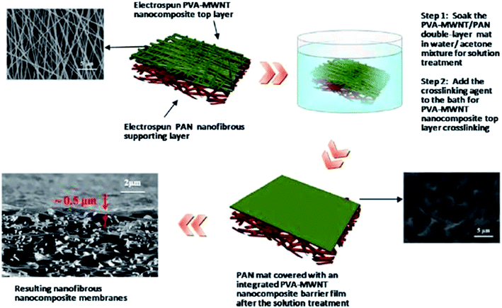 | ||
| Fig. 11 Typical fabrication process for a TFC membrane based on an ENM substrate and a crosslinked PVA-MWCNT barrier layer. Reproduced with permission from ref. 48. Copyright 2013, Elsevier Science Ltd. | ||
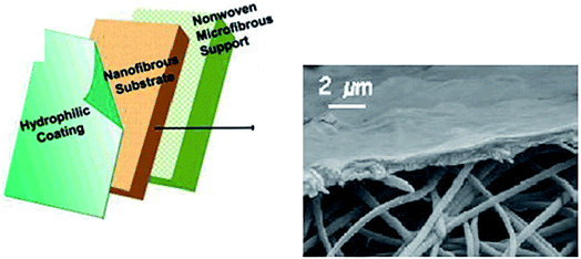 | ||
| Fig. 12 A three-layered TFC membrane (the hydrophilic coating can be prepared by cast coating, cross linking, or interfacial polymerization (IP)) with a hydrophilic coating layer, a fibrous (TFNC/ENM) substrate, and a nonwoven substrate. The layers have average thicknesses of 0.2, 40, and 130 μm, respectively. Reproduced with permission from ref. 39. Copyright 2005, the American Chemical Society. | ||
The concept of thin-film coated electrospun nanofibrous membranes was first applied to organic-solute rejection in water/oil separation. The use of TFNC membranes dates back to 2005 when a PVA/chitosan-hydrogel thin film was used as the top/active cast-coated layer on a chemically cross-linked (using glutaraldehyde) ENM substrate. The resulting TFNC ultrafiltration (UF) membrane was applied to the separation of colloidal solutions, such as water/oil suspensions. It is preferable that the cross-linking of the ENM has little or no effect on the membrane structure (e.g., porosity or fiber diameter) in order to retain its structural performance. In other words, crosslinking should result in the minimal degree of membrane shrinkage; for example, a 2% decrease in porosity is usually acceptable.8,39 UF membranes with top active thin-film layers produced by casting, cross linking, or phase polymerization, were later developed into NF membranes with top thin-film-coating layers by the interfacial polymerization of polyamides onto the cross-linked electrospun nanofibers. Since then, interfacial polymerization has been commonly used to prepare membranes for the filtration of salt/seawater.
Interfacial polymerization involves the formation of a selective, highly cross-linked ultrathin polymer (usually polyamide) film with a thickness of about 300 nm, and with a network structure at the interface between the two immiscible solutions (in which the two monomers are dissolved) following rapid chemical reaction. The parameters of this process determine the performance of the resultant TFNC membrane. Additives, such as piperazine comonomer, and their concentrations, play important roles in enhancing the flux, salt rejection, and strength of the thin-film selective layer. Due to the non-porous nature of the thin film, additives are incorporated in order to enhance permeability.10
The resulting nonporous thin-film top layer, however, offers resistance to the flow of liquid through the membrane, especially those prepared by IP. The less-porous or less-permeable (or macroscopically nonporous) TFNC barrier/thin-film layer therefore requires further treatment or modification using additives in order enhance permeability for increased membrane flux, while maintaining high salt rejection. Enhancing hydrophilicity is the most popular strategy for improving permeability, chlorine resistance, and fouling resistance. Another approach uses ENMs as porous thin-film layers, as discussed above.
4.3.1.1. Permeability enhancement. The incorporation of MWCNTs into a thin film can result in the development of microscopic or nanosized surface channels that promote water flow through the membrane, which increases both permeability and flux. The inclusion of nanoparticles in the top layer/thin-film results in the formation of what is referred to as a “nanocomposite coating layer”.39 Other surface modifications that incorporate nanoparticles should, however, not hinder salt-rejection performance of the already nonporous membrane/active layer. Permeability has also been enhanced through the use of AgNPs, TiO2, SiO2, and zeolites, as well as organic additives, such as surfactants and solvents, while maintaining salt rejection.42
The hydrophilic nonporous top-layer thin-film coating is more compatible with a hydrophilic nanofibrous ENM substrate. Hydrophobic substrates result in less contact between the membrane and the thin film during polymerization; hence surface treatment is required to increase its hydrophilicity. Polymers with good thermal and chemical resistance that are easy to process and biocompatible are preferred. The most commonly used examples include PVA, polyvinyl difluoride (PVDF), and polysulfone (PS). PVDF and PS also exhibit superior water stabilities. On the other hand, water-soluble polymers, such as PVA, are required to undergo crosslinking (with aldehydes) prior to application in order to impart water resistance/stability, thereby preventing the dissolution of the membrane in aqueous environments. Thereafter, these membranes undergo shrinkage and water-stability testing, including water-solubility and water-absorbency testing, including swelling degree experiments, which determine the level of cross linking, in addition to mechanical testing. This testing regime determines the stability of an ENM membrane in an aqueous environment. PVA does not degrade under physiological conditions and has been used as both the coating and mid layers of a membrane. As a top layer, a cross-linked PVA hydrogel that forms a nonporous thin film was devised with added MWCNTs for permeability, which resulted in a high-flux membrane. Other hydrophilic polymers such as PAN, poly(ether ether ketone), polyimide (PA), poly(phthalazinone ether ketone), polypropylene (PP), and hydrolyzed cellulose acetate (CA) have also been used as ENM supports.7,39
4.4 Membrane fabrication for MD
Membrane design and fabrication are of utmost importance for efficient desalination performance. Conventional membrane fabrication methods, such as phase inversion, produces membranes with large pores, high tortuosities, low hydrophobicities or surface roughnesses, and low porosities; consequently, they are not ideal for MD or any desalination process due to low fluxes and rejections.5 Likewise, ENM pores are also large; consequently, nanotechnology is required during their preparation, which involves the inclusion of nanoparticles/nanofibers and high levels of modification.52–54 Since membrane technology plays a crucial role in desalination performance, new materials and fabrication methods for desalination membranes have been developed through progress in science and technology. As the aim of a desalination membrane is high salt rejection while maintaining high flux,8 several factors that play roles in determining performance, such as membrane structure (porosity, thickness, and polymer/membrane surface properties), need to be considered. Unlike RO, ENMs for MD applications can either be used as single (main membrane) layers or as support membranes (in multiple dual- or triple-layer systems). These are then applied in single layers as pre-filters that are placed upstream to enhance/protect the life of the more-delicate RO-filter membranes, or as direct filter membranes in UF or MD separations. As mid-layers they support the delicate top active layer in a multilayer composite membrane for NF or RO applications, and they can only be used independently in MD. For these reasons, ENMs are more promising for MD applications than other desalination technologies.8,55–62Since MD is a thermally driven process, single layers, as unsupported self-standing membranes, are more ideal for applications such as DCMD, in which they are not exposed to any harsh hydraulic/osmotic pressures. Although MD offers many advantages over other desalination processes, the membrane-fabrication methods, however, are continuously being improved in terms of structure and design in order to enhance the low permeation flux.21 For this reason, membrane design that particularly uses electrospinning, which is an emerging membrane-fabrication technique, needs further research. Membrane pore sizes can easily be adjusted by electrospinning, for example through the careful control of fiber diameter.63–65
| Polymer material/concentration | Fiber diameter (nm) | Mean pore size (μm) | Process | Nanoparticles/treatment used | Contact angle (°) | Reason for the effect of membrane surface on flux performance | Permeation flux (L m−2 h−1) | Reference |
|---|---|---|---|---|---|---|---|---|
| a Commercial phase-inversion PVDF membrane@20 L m−2 h−1; NaCl concentration of 35 g L−1@60 °C.b PMMA, poly(methyl methacrylate); PVDF, polyvinylidene fluoride; PVDF-HFP, polyvinylidene fluoride-co-hexafluoropropylene; PS, polystyrene; PDMS, polydimethylsiloxane; PSF, polysulfone. | ||||||||
| PMMA | >1000 | >9 | DCMD | PDMS | Superhydrophobic, 163° | Surface roughness | 39.61 L m−2 h−1@99.96% | 85 |
| aCommercial PVDF | 450 | 0.28 | 135° | 20 L m−2 h−1 | 86 | |||
| PVDF-HFP, 20 wt% | Neat: 336 | 0.59 | DCMD | CNT (2–3%), 5–20 nm | 150° | Good dispersion of the CNT-NPs within the fibers | Before: 34 | 87 |
| Treated: 288 | 0.65–1.12 | After: 48 L m−2@3% loading | ||||||
| PVDF-HFP, 20, 15, 10 wt% | Neat: 368 | 0.88 | DCMD | FTES-TiO2 (21 nm, 1–10%) functionalized | Hydrophobic, 149° | TiO2 NPs on fiber surfaces | Neat: 25 | 88 |
| Treated: 296–135 | 0.87–0.41 | After: 40, L m−2 h−1 | ||||||
| Matrimid, 18 wt% | 290 | 2000 | DCMD | None | 130° | 56 kg m−2 h−1 | 89 | |
| PVDF, 5 wt% | Neat: 150 | 0.31 | DCMD | AgNPs on activated nanofibers/membranes | Neat: 138 hydrophobic | Open pore structure | Before: 35.7 | 86 |
| Treated: 293 | 0.34 | 153 superhydrophobic | After: 31.6, L m−2 h−1 | |||||
| Porous graphene | Molecular sieves | 0.41–0.56 | RO | None | Hydrophobic | Non-circular nanopores | 2500 L m−2 h−1 bar permeability@100% salt rejection | 90 |
| PVDF, 5 wt% | 90 beaded | 0.68 | DCMD | Modified SiO2 | 143 > 156 (increases with NP size), superhydrophobic | Micro and nano surface roughness | 19 kg m−2 h−1 | 91 |
| 0.77 | Mixture of 5–10 nm and 200–300 nm | |||||||
| PS, 15–30 wt% | DCMD | Micro-grooved morphology of the micro/nanofibers | 4.5 kg m−2 h−1@ 50 °C | 92 | ||||
| PVDF-HFP | 718 | 2.23 | SiNPs (silanized) | 130 | 25 L m−2 h−1 | 93 | ||
| 197 | 0.26 | 150 | 15 L m−2 h−1 | |||||
| PVDF and PSF | 710 and 800 | Large and small pores | DCMD | None, dual membrane layers | 132 & 141 | Dual-membrane combined hydrophobicity/hydrophilicity involving shorter distances between the vapor/liquid interfaces and low mass-transfer resistance | 48 kg m−2 h−1 | 6 |
| PVDF-HFP 20 wt% and PVA/N6/PAN 10 wt% | Before: 239 | Before: 0.34 | AGMD | None, dual membrane layers + heat treatment | 148 | Heat treatment results in fused fibers that prevent the penetration of the liquid through the membrane | 10.9–15.5 L m−2 h−1 | 40 |
| After heat treatment: 302–333 | After: 0.130–0.40 | 122–149 (after) | ||||||
| PVDF-HFP, 20 wt% | 0.39 | 0.50 | DCMD | None, heat treated | 150 | Membrane compaction by heat treatment resulting in lower thickness and lowers mass-transfer resistance | 29 | 94 |
| 0.550–0.75 | 0.41–0.48, 0.42 | 143 (less hydrophobic) | ||||||
| PVDF | 0.18 | DCMD | Heat treated | 141 | Reduced pore wetting by heat treatment | 20.6 | 95 | |
| 0.21 | 138 | |||||||
| PVDF, 12 wt% | 0.417 | 0.58 | Clay (8%) | 129 | The hydrophobicity of the membrane reduces pore wetting | 6 kg m−1 h−1 | 96 | |
| 0.5–0.625 | 0.6–0.64 | 154 superhydrophobic | ||||||
| PVDF, 8 wt% | 0.3–0.4 | 0.28–0.49 & 0.41–0.63 | FO | 12.7–19.4, 30.4 L m−2 h−1 | 96 | |||
Since MD membranes can be fabricated in single, dual, or triple layers, they have simpler designs compared to those used in RO and NF. As the required pores are in the microfiltration/ultrafiltration range, MD membranes can be produced in a single process, such as electrospinning; i.e., without an additional selective-layer coating by interfacial polymerization, as used in the fabrication of TFNC membranes for RO. Therefore unsupported single-layered membranes (i.e., self-sustained membranes) only consist of a hydrophobic layer when electrospun. As they are self-supporting, they are required to be mechanically and chemically stable. MD also uses multi/dual layers in which the top hydrophobic layer is coupled with a hydrophilic backing layer. Therefore, recent studies use a combination of hydrophobic and hydrophilic layers to form a bilayer of composite MD membrane, i.e., the hydrophobic membrane is modified by introducing a hydrophilic support layer. The underlying hydrophilic layer, together with its high porosity, aids in enhancing the permeate flux of the top hydrophobic membrane, while maintaining high salt rejection. Ray et al.99 produced a dual layered membrane consisting of electrospun polypropylene (PP) as top hydrophobic layer and PVA as 2nd hydrophilic layer form a composite membrane. The added surfactant helps to form a membrane with thinner uniform fiber diameters and thus smaller pore sizes and higher surface area. Thus the hydrophilicity of bottom layer enhanced by surfactant formed an overall membrane with higher water adsorption, therefore higher flux, due to the formation of nano-channels that resulted in high pore volume.99 Single layers with or without a backing layer have also been employed in MD.21
4.4.3.1 Thickness of the active layer. The thickness of an electrospun membrane is tailored during fabrication by adjusting the duration of the electrospinning process. Thickness also plays an important role in the overall membrane performance, and the membrane is usually considered to be thin when it is less than 400 μm thick. For example, while the mass/vapor-transfer resistance of a membrane increases with increasing thickness, the permeate flux decreases due to increases in mass-transfer resistance that result from the longer transport pathway.21 While thinner membranes can be used in thermal processes, it is worth noting that thicker membranes are beneficial for thermal resistance and mechanical stability in MD processes. The required thickness also depends on the membrane support and type of feed solution (salt concentration). However, wetting increases with decreasing membrane thickness due to liquid penetration through the pores. The effective thickness of the support layer is defined as: S = tτ/ε, where t is the thickness, τ is the tortuosity, and ε is the porosity of the support membrane; this is also known as the effective diffusive path and determines the mass-transfer resistance, which needs to be lowered by lowering thickness and increasing porosity.102,103 A study by Essalhi and Khayet5 used electrospun PVDF membrane as a single hydrophobic layer membrane, with optimized thickness. As the thickness is one of the membrane properties that affect the membrane performance such as flux and thermal resistance, the thickness was adjusted at varying feed concentration and temperature, in order to investigate its effect on MD performance. Although thickness is beneficial for energy efficient for MD process, thinner membranes however, achieve higher permeate fluxes due to increased permeability, as flux is inversely proportional to membrane thickness, their larger pore sizes, higher porosity and lower tortuosity.5 Another interesting study by Khayet et al.6 demonstrated how the membrane flux can be enhanced substantially, by optimizing the thickness of the underlying layer rather than introducing an underlying hydrophilic layer below the hydrophobic top layer. Thus the increased flux with the reduced thickness was due to increase in membrane pore size and porosity to facilitate easy water transport through the dual layered membrane.6 For pressure-driven processes, reducing the membrane thickness, in an attempt to increase the permeate flux, should not sacrifice the mechanical integrity of the membrane due to the high pressure. A lack of membrane-thickness uniformity remains a challenge for ENMs.21,23 Therefore, increases in thickness are highly beneficial for mass-transfer resistance, good mechanical stability and strength, and permeability.
4.4.3.2 Membrane pores. The most important characteristic of the MD-membrane pores is dryness, which can be successfully achieved without impacting permeability through the use of hydrophobicity and small pores.104 Adjusting the sizes of the membrane pores during electrospinning involves tuning certain parameters, such as the composition of the polymer solution, humidity, and the needle speed (horizontal translation). As the feed water should not penetrate into the membrane pores, the operating or hydrostatic-process pressure must not exceed the liquid-entry pressure (LEP) of the membrane. LEP refers to the minimum transmembrane pressure, or the pressure at which the liquid can enter the membrane pores, and depends on the maximum pore size, shape, and hydrophobicity. Since the LEP and the feed concentration are directly related, this value may be higher for feed solutions with high NaCl contents, such as seawater, due to increased surface tension. It is therefore preferable that the hydrostatic pressure is lower than the LEP to avoid pore wetting. Hence higher LEP values can be obtained and maintained with higher hydrophobicities, smaller pores (that do not affect the membrane permeability), and thicker membranes. Decreases in the LEP value resulting from increased in the thickness of the hydrophilic layer in a dual-layer membrane are attributed to increases in the inter-fiber space.5,21,68 However, along with membrane fouling, scaling and membrane wetting can still occur. Therefore, the hydrostatic pressure must be lower than the LEP, and can be calculated using the Laplace equation:
 | (3) |
4.4.3.3 Pore size and distribution. Pore size refers to the mean pore size, while distribution refers to the variety of pore sizes within the membrane, particularly those prepared by electrospinning. Electrospun nanofibrous membranes usually have pores around 0.1–1 μm in size; therefore these MF pores are suitable for MD use. Large pores provide higher permeate fluxes; however they should be small enough to prevent water penetration, while maintaining good permeability.92 A mass-transfer mechanism exists for each pore-size distribution. The pore size distribution (PSD) is mainly affected by the diameters of the membrane fibers because pore size is inversely proportional to fiber diameter. The pores in an MD membrane should vary little in size. Narrow pore-size distributions (associated with thin fibers) and small pores of about 0.60 μm in size, or less, are preferred. A larger PSD leads to pore wetting/penetration, which allows solutes from the feed to pass through the membrane (low rejection). Unfortunately only a 25% increase in pore size during operation can be accommodated. In MD, the flow of vapor is governed by mechanisms that depend on the sizes of the pores within the membrane; these include Knudsen diffusion, Poiseuille/viscous flow, and molecular diffusion.64,65 Su et al.69 observed that a pore-diameter distribution for their electrospun PVDF mid-layer/support membrane centered at about 390 nm gave the best DCMD performance. Better pore characteristics and structure are indicated by a narrower pore distribution and a more focused (sharper) maximum peak. Pore-size distribution also affects water quality in terms of conductivity; narrower pore-size distributions provide higher water quality as fewer ions permeate through the membrane. Commercial membranes have narrow pore-size distributions; hence they display better pore properties than ENMs. For example, a commercial PTFE membrane has a pore-size distribution of 0.1–0.35 μm, compared to that of an electrospun PVDF (0.2–0.8 μm) with a 220 nm average fiber diameter. However, it is worth noting that the ENMs from co-polymers often exhibit better performance compared to membranes with narrower pore-size distributions. The PVDF co-polymer resulted a membrane with better performance than commercial membranes due to its narrower pore-size distribution, thinner fibers, and better contact angle (hydrophobicity); consequently, they are preferred for MD applications over PVDF ENMs.69 Fig. 13 displays nanofibrous membranes modified with AgNPs and their corresponding pore-size distributions. Hydrophobicity or surface-roughness modifications resulting from the incorporation of nanoparticles affect the pore sizes and the pore-size distributions of the membranes. Fig. 13 shows that the once bare fibers in panel (a) become covered with nanoparticles, which reduces the sizes of the pores, as seen in panel (b). However, panel (c) reveals that full coverage of the membrane with a layer of particles leads to complete pore blockage, which often has a detrimental effect on membrane performance due to decreased water permeability and, consequently, reduced flux; it well established that pore-size distribution affects water flux.86 Surface modifications therefore need to be effective or optimized in such a way that the sizes and distributions of the pores are not affected. For example, the pore-size distributions of the modified and unmodified membranes shown in Fig. 14(a and b) that correspond to the images in Fig. 13(a and b) are quite similar, and compete with those of the commercial membrane shown in panel (c). The narrow pore-size distribution is unaffected by the inclusion of AgNPs, unlike the broad pore-size distribution that results from blocked pores following ineffective surface modification, as shown in Fig. 14(c). Other membrane-surface modifications, such as heat treatment, also result in pore sizes that remain narrowly distributed, however reduced fluxes are observed.40,105 Although the incorporation of NPs seems to increase the fiber diameter more than heat treatment, the former membranes exhibit enhanced performance compared to the latter.55,67,75,106–108
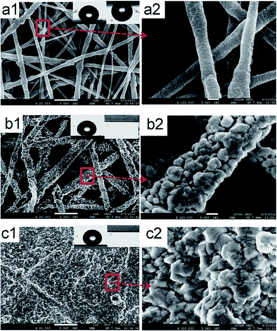 | ||
| Fig. 13 SEM images of superhydrophobic nanofibrous membranes with and without the incorporation of AgNPs. (a) Before modification (pristine fibers), (b) after fiber coating (AgNPs are deposited onto individual fibers), and (c) after membrane-surface coating (AgNPs cover the entire membrane surface). Reproduced with permission from ref. 86. Copyright 2012, Elsevier Science Ltd. | ||
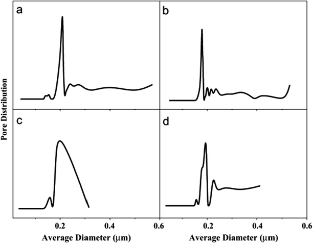 | ||
| Fig. 14 Pore-size distributions of the electrospun PVDF membranes depicted Fig. 13: (a) unmodified, (b) fully modified (individually coated fibers), (c) coating only on the membrane surface, and (d) a commercial PVDF membrane for comparison. Reproduced with permission from ref. 86. Copyright 2012, Elsevier Science Ltd. | ||
4.4.3.4 Porosity or void-volume fraction. Like membranes used in other desalination processes, porosity is required to be as high as possible for adequate vapor transport, and low thicknesses and tortuosities are required. Porosity, which is the void-volume fraction of the membrane, can either be surface or volumetric porosity. ENMs for MD have large porosities (of up to 90%), enhanced permeation fluxes (permeabilities), as well as large surface areas for evaporation, and numerous pore channels for diffusion. High porosity also means more voids; hence the presence of low-conductivity air spaces help to increase the thermal resistance (heat efficiency) of the membrane. The porosity should be neither too high nor too low. A high porosity detrimentally affects the mechanical properties of the membrane. MD membranes with porosities in the 35–93% range have been prepared; for example, the porosity of an electrospun PVDF membrane is 79%, while that of a commercial PVDF is 62%.21,24,109 Porosity can be determined gravimetrically as the volume of the pores divided by the total volume of the membrane:40
 | (4) |
Tortuosity refers to the lack of straightness of the pore channels; the higher the tortuosity, the lower the permeability. A cylindrical channel has a tortuosity that is close to unity and is desirable for MD.110,111
4.4.3.5 Hydrophobicity. The material composition (polymer type) and the geometrical structure of the surface determines the hydrophobicity (or surface energy) of the membrane. The role of a hydrophobic membrane surface in MD is to prevent membrane wetting or pore penetration by the liquid phase (feed water), thereby facilitating the penetration of only the vapor phase.10 Conventional MD membranes are typical MF membranes prepared by phase-inversion using hydrophobic polymers such as PP, PTFE, and PVDF, with contact angles of ∼138° that are higher than those of flat-fabricated PVDF membranes (128°), and have good chemical and thermal properties. The electrospinning of these polymers affords membranes with better hydrophobicities owing to the surface roughnesses by the nanofibers; consequently, low contact between the solid and liquid surfaces is achieved, which, in turn, leads to a higher contact angle (CA). Polymer hydrophobicity can also be enhanced through modification with hydrophobic additives or low-surface-energy materials, such as hydrophobic NPs, in the polymer matrix, molecular and functional-group modifications, or by introducing or increasing surface roughness. The water contact angles of these membranes before and after surface modification are depicted in Fig. 15. Surface modification techniques, such as plasma treatment and layer-by-layer assembly, can also be used.112–114 A superhydrophobic surface is obtained by increasing the surface roughness of two materials with different hydrophobicities; materials with high contact angles (>150°) are considered to be superhydrophilic or ultrahydrophobic; i.e., a water droplet on the polymer surface will exhibit a low sliding angle or contact angle hysteresis of less than 10°, which is the difference between the contact angles of the front and back edges of the water droplet.113,115 Hydrophobicity enhances membrane performance in MD, including improved salt rejection and reduced pore wetting.20,116,117 Hydrophobicity affects the membrane-filtration efficiency; hydrophobicity is the result of membrane-surface roughness, while hydrophilicity is associated with smoothness. The ENMs are rendered rough due to air pockets formed between the fibers, which lead to increased hydrophobicity compared to the unspun membrane. Hydrophobicity, which is determined by contact-angle measurements, is required to be as high as possible for the DCMD process, and membranes or polymers with higher contact angles are usually preferred for MD applications. PVDF-HFP, with a high contact angle of 128°, provided more satisfactory results than the commercial PTFE with the lower contact angle of 115°.8,69
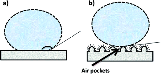 | ||
| Fig. 15 Examples of water contact angle on (a) a hydrophilic membrane surface and (b) a hydrophobic surface (e.g., after surface modification). Reproduced with permission. Reproduced with permission from ref. 86. Copyright 2014, Elsevier Science Ltd. | ||
4.4.3.6 Thermal properties of membranes. The membrane material should have a low thermal conductivity as well as good thermal resistance. High membrane porosities are associated with low thermal conductivities, as the presence of more air within the pores helps to reduce heat transfer by conduction. Another method involves the use of multilayers (dual layers with a hydrophobic top layer on a hydrophilic layer/support), in which the thickness of the support helps to lower heat conductivity.
4.4.3.7 Post-electrospinning heat treatment. Hot pressing is the most common heat treatment for electrospun desalination membranes, and involves membrane compaction by pressing between two plates at a temperature above the glass-transition temperature (Tg), but below the melting temperature (Tm), resulting in the fusion of fibers at their points of intersection. Studies have shown that the surface roughness and hydrophobicity are reduced (contact angle reduction of 10%) following heat treatment. Hot pressing not only reduces the thickness, but also the pore size, pore-size distribution, pore volume, and porosity (20–30% reduction), while the fiber diameter is increased (by about 39%) due to fiber swelling and morphology smoothing; however improved flux as well as mechanical properties are also observed. The fused fibers are more tightly packed, thereby preventing the penetration of water into the membrane pores, which avoids a reduction in mass-transfer across the membrane and increases the flux.21,40,70,95
Temperature. MD flux increases with increasing flowrate and temperature difference, as shown in Fig. 16.
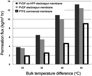 | ||
| Fig. 16 Plot depicting the effect of temperature difference on MD performance. Reproduced with permission from ref. 69. Copyright 2012, Springer Verlag. | ||
4.5 New RO and MD technologies
One of the latest trends in RO and MD desalination involves the inclusion of nano-sized materials that aid the desalination process. Non-polymeric materials include carbon-based particles (carbon nanotubes (CNTs) and graphene), zeolites, aquaporin (AQP),87,119–122 and molecular sieves.90,123–127 Nanomaterials, such as CNTs, increase nanofiber roughness through the creation of air pockets;128 they enhance the fluxes of RO TFNC membranes and MD, which increases with higher nanoparticle content. Incorporation of CNTs within the nanofiber polymer matrix provides the added advantage of fiber thinning during electrospinning due to their high conductivities.129 However, irrespective of the uniform pore-size distribution (that minimizes wetting), pore size increases with higher CNT content (∼3 wt%), as does the flux. At this content, irrespective of the higher flux, the large pore sizes result in reduced LEP, which may be due to CNT-nanoparticle agglomeration. Kyoungjin An et al. and Lee87 determined the optimum CNT content to be 0.5% wt%, above which agglomeration begins. The unique water-transport properties of CNTs and graphene create nano-channels that facilitate water flow and, as a consequence, result in high-flux membranes, with fluxes that increase with CNT content.87 Highly porous zeolites offer cavities for water transport, while the sizes of the pores produced make them exceptional for retaining salt ions from the water stream. In addition to adsorption and sieving, the ion-exchange properties are an added advantage. AQPs are types of biological membrane that also offer effective water transport pathways while retaining ions. These novel materials are incorporated into the polymer matrix of the membrane during fabrication, thereby improving membrane properties, such as permeability (hydrophilicity), fouling, and salt permselectivity. For example, graphene-incorporate ENMs exhibit enhanced membrane superhydrophobicity, porosity, and LEP, for MD applications.1,8,130,1315. Conclusion and future outlook
Among membrane technologies for water treatment, RO and MD are the most relevant for the separation of salt and are therefore the most commonly used for seawater desalination. While thermally based techniques are first-generation, membrane-based methods are second-generation technologies. RO is the best of the pressure-driven membrane processes, which uses membranes with pore sizes well below 1 nm that can be formed through surface modification by thin-film coating; hence RO is capable of removing all types of ions, including those of monovalent salts, and is therefore the most suited for desalination applications. MD on the other hand is also theoretically capable of completely removing salts/NaCl (100% rejection). Nanotechnology involving the use of nanofibers is a fast-growing area of research. As a consequence, electrospinning is considered to be a feasible method for the production of nanomaterial substrates with high surface porosities and interconnected pore structures for pressure-driven and thermally based membrane processes. ENMs have been applied to desalination in limited ways due to their large pores that are incapable of removing salts, which is the reason why these membranes have not been used as top active layers or single-layer self-supported membranes in RO desalination. Electrospun nanofibrous membranes that have undergone crosslinking can directly take part in the RO separation process (i.e., as a top layer). So far, ENMs, as top active selective/barrier layers, have only been successfully used in UF-separation applications, which suggest that future ENM-growth opportunities exist in both MD and RO operating environments.Conflicts of interest
There are no conflicts to declare.Acknowledgements
The authors would like to thank the Department of Science and Technology (HGERA8X) and the Council for Scientific and Industrial Research (HGER74P), South Africa for financial support.References
- Y. H. Teow and A. W. Mohammad, Desalination, 2017, 356, 226–254 Search PubMed.
- M. A. Shannon, P. W. Bohn, M. Elimelech, J. G. Georgiadis, B. J. Mariñas and A. M. Mayes, Nature, 2008, 452, 301–310 CrossRef CAS PubMed.
- C. Feng, K. C. Khulbe, T. Matsuura, R. Gopal, S. Kaur, S. Ramakrishna and M. Khayet, J. Membr. Sci., 2008, 311, 1–6 CrossRef CAS.
- M. Elimelech and W. A. Phillip, Science, 2011, 333, 712–717 CrossRef CAS PubMed.
- M. Essalhi and M. Khayet, J. Membr. Sci., 2013, 433, 167–179 CrossRef CAS.
- M. Khayet, M. C. García-Payo, L. García-Fernández and J. Contreras-Martínez, Desalination, 2018, 426, 174–184 CrossRef CAS.
- K. P. Lee, T. C. Arnot and D. Mattia, J. Membr. Sci., 2011, 370, 1–22 CrossRef CAS.
- S. Subramanian and R. Seeram, Desalination, 2013, 308, 198–208 CrossRef CAS.
- S. S. Ray, S.-S. Chen, D. Sangeetha, H.-M. Chang, C. N. D. Thanh, Q. H. Le and H.-M. Ku, Environ. Chem. Lett., 2018, 16, 1–4 CrossRef.
- Y. Liao, C.-H. Loh, M. Tian, R. Wang and A. G. Fane, Prog. Polym. Sci., 2018, 77, 69–94 CrossRef CAS.
- S. S. Shenvi, A. M. Isloor and A. F. Ismail, Desalination, 2015, 368, 10–26 CrossRef CAS.
- R. Gopal, S. Kaur, Z. Ma, C. Chan, S. Ramakrishna and T. Matsuura, J. Membr. Sci., 2006, 281, 581–586 CrossRef CAS.
- K. Yoon, B. S. Hsiao and B. Chu, J. Mater. Chem., 2008, 18, 5326–5334 RSC.
- A. G. Fane, W. Rong and M. X. Hu, Angew. Chem., Int. Ed., 2015, 54, 3368–3386 CrossRef CAS PubMed.
- K. Yoon, K. Kim, X. Wang, D. Fang, B. S. Hsiao and B. Chu, Polymer, 2006, 47, 2434–2441 CrossRef CAS.
- Z. Zhao, J. Zheng, M. Wang, H. Zhang and C. C. Han, J. Membr. Sci., 2012, 394–395, 209–217 CrossRef CAS.
- K. Yoon, B. S. Hsiao and B. Chu, J. Membr. Sci., 2009, 338, 145–152 CrossRef CAS.
- G. Xuefei, X. Li-Ping, X. Zhongxin, F. Lin, P. Jitao, W. Yongqiang, W. Shutao and Z. Xueji, Adv. Mater., 2014, 26, 1771–1775 CrossRef PubMed.
- Z. Karim, A. P. Mathew, M. Grahn, J. Mouzon and K. Oksman, Carbohydr. Polym., 2014, 112, 668–678 CrossRef CAS PubMed.
- Y. C. Woo, L. D. Tijing, M. J. Park, M. Yao, J.-S. Choi, S. Lee, S.-H. Kim, K.-J. An and H. K. Shon, Desalination, 2017, 403, 187–198 CrossRef CAS.
- L. D. Tijing, J.-S. Choi, S. Lee, S.-H. Kim and H. K. Shon, J. Membr. Sci., 2014, 453, 435–462 CrossRef CAS.
- E. Drioli, A. Ali and F. Macedonio, Desalination, 2015, 356, 56–84 CrossRef CAS.
- M. S. El-Bourawi, Z. Ding, R. Ma and M. Khayet, J. Membr. Sci., 2006, 285, 4–29 CrossRef CAS.
- H. Maab, L. Francis, A. Al-saadi, C. Aubry, N. Ghaffour, G. Amy and S. P. Nunes, J. Membr. Sci., 2012, 423–424, 11–19 CrossRef CAS.
- B. S. Lalia, V. Kochkodan, R. Hashaikeh and N. Hilal, Desalination, 2013, 326, 77–95 CrossRef CAS.
- T. Subbiah, G. S. Bhat, R. W. Tock, S. Parameswaran and S. S. Ramkumar, J. Appl. Polym. Sci., 2005, 96, 557–569 CrossRef CAS.
- F. E. Ahmed, B. S. Lalia and R. Hashaikeh, Desalination, 2015, 356, 15–24 CrossRef CAS.
- N. Bhardwaj and S. C. Kundu, Biotechnol. Adv., 2010, 28, 325–347 CrossRef CAS PubMed.
- R. S. Barhate, C. K. Loong and S. Ramakrishna, J. Membr. Sci., 2006, 283, 209 CrossRef CAS.
- A. Haider, S. Haider and I.-K. Kang, Arabian J. Chem., 2015 DOI:10.1016/j.arabjc.2015.11.015.
- S. Huan, G. Liu, G. Han, W. Cheng, Z. Fu, Q. Wu and Q. Wang, Materials, 2015, 8, 2718–2734 CrossRef CAS.
- H.-J. Choi, S. B. Kim, S. H. Kim and M.-H. Lee, J. Air Waste Manage. Assoc., 2014, 64, 322–329 CrossRef CAS.
- J. M. Deitzel, J. Kleinmeyer, D. Harris and N. C. Beck Tan, Polymer, 2001, 42, 261–272 CrossRef CAS.
- C. J. Angammana and S. H. Jayaram, Part. Sci. Technol., 2016, 34, 72–82 CrossRef CAS.
- D.-G. Yu, J. Zhou, N. P. Chatterton, Y. Li, J. Huang and X. Wang, Int. J. Nanomed., 2012, 7, 5725–5732 CrossRef CAS PubMed.
- Q. P. Pham, U. Sharma and A. G. Mikos, Biomacromolecules, 2006, 7, 2796–2805 CrossRef CAS PubMed.
- K. H. Lee, H. Y. Kim, M. S. Khil, Y. M. Ra and D. R. Lee, Polymer, 2003, 44, 1287–1294 CrossRef CAS.
- S. S. Ray, S.-S. Chen, C.-W. Li, N. C. Nguyen and H. T. Nguyen, RSC Adv., 2016, 6, 85495–85514 RSC.
- X. Wang, X. Chen, K. Yoon, D. Fang, B. S. Hsiao and B. Chu, Environ. Sci. Technol., 2005, 39, 7684–7691 CrossRef CAS PubMed.
- Y. C. Woo, L. D. Tijing, M. J. Park, M. Yao, J. S. Choi, S. Lee, S. H. Kim, K. J. An and H. K. Shon, Desalination, 2017, 403, 187–198 CrossRef CAS.
- H. You, Y. Yang, X. Li, K. Zhang, X. Wang, M. Zhu and B. S. Hsiao, J. Membr. Sci., 2012, 394–395, 241–247 CrossRef CAS.
- X. Wang, H. Ma, B. Chu and B. S. Hsiao, Desalination, 2017, 420, 91–98 CrossRef CAS.
- G.-R. Xu, J.-N. Wang and C.-J. Li, Desalination, 2013, 328, 83–100 CrossRef CAS.
- D. Li, Y. Yan and H. Wang, Prog. Polym. Sci., 2016, 61, 104–155 CrossRef CAS.
- W. J. Lau, A. F. Ismail, N. Misdan and M. A. Kassim, Desalination, 2012, 287, 190–199 CrossRef CAS.
- L. Eykens, I. Hitsov, K. De Sitter, C. Dotremont, L. Pinoy, I. Nopens and B. Van der Bruggen, J. Membr. Sci., 2016, 498, 353–364 CrossRef CAS.
- M. Elma, C. Yacou, D. K. Wang, S. Smart and J. C. Diniz da Costa, Water, 2012, 4, 629–649 CrossRef CAS.
- M. M. A. Shirazi, A. Kargari, S. Ramakrishna, J. Doyle, M. Rajendrian and R. Babu, J. Membr. Sci. Res., 2017, 3, 209–227 Search PubMed.
- P. S. Suja, C. R. Reshmi, P. Sagitha and A. Sujith, Polym. Rev., 2017, 57, 467–473 CrossRef CAS.
- K. Satinderpal, S. Subramanian, G. Renuga and R. Seeram, J. Appl. Polym. Sci., 2012, 124, E205–E215 CrossRef.
- X. Wang, K. Zhang, Y. Yang, L. Wang, Z. Zhou, M. Zhu, B. S. Hsiao and B. Chu, J. Membr. Sci., 2010, 356, 110–116 CrossRef CAS.
- M. I. Litter, W. Choi, D. D. Dionysiou, P. Falaras, A. Hiskia, G. Li Puma, T. Pradeep and J. Zhao, J. Hazard. Mater., 2012, 211–212, 1–2 CrossRef CAS PubMed.
- X. Qu, P. J. J. Alvarez and Q. Li, Water Res., 2013, 47, 3931–3946 CrossRef CAS PubMed.
- M. Wiesner, Q. Li, J. Burgess, R. Kaegi and D. Dixon, Water Res., 2013, 47, 3865–4206 CrossRef CAS PubMed.
- Y. C. Woo, L. D. Tijing, W.-G. Shim, J.-S. Choi, S.-H. Kim, T. He, E. Drioli and H. K. Shon, J. Membr. Sci., 2016, 520, 99–110 CrossRef CAS.
- C. Feng, K. C. Khulbe, T. Matsuura, S. Tabe and A. F. Ismail, Sep. Purif. Technol., 2013, 102, 118–128 CrossRef CAS.
- M. Mavroudi, S. P. Kaldis and G. P. Sakellaropoulos, J. Membr. Sci., 2006, 272, 103–115 CrossRef CAS.
- M. Essalhi and M. Khayet, J. Membr. Sci., 2013, 433, 180–191 CrossRef CAS.
- C. Burger, B. S. Hsiao and B. Chu, Annu. Rev. Mater. Res., 2006, 36, 333–368 CrossRef CAS.
- L. A. Hoover, J. D. Schiffman and M. Elimelech, Desalination, 2013, 308, 73–81 CrossRef CAS.
- A. Amarjargal, L. D. Tijing, M. T. G. Ruelo, D. H. Lee and C. S. Kim, Mater. Chem. Phys., 2012, 135, 277–281 CrossRef CAS.
- L. D. Tijing, C.-H. Park, S.-J. Kang, A. Amarjargal, T.-H. Kim, H. R. Pant, H. J. Kim, D. H. Lee and C. S. Kim, Appl. Surf. Sci., 2013, 264, 453–457 CrossRef CAS.
- K. Yu Wang, T.-S. Chung and M. Gryta, Chem. Eng. Sci., 2008, 63, 2587–2594 CrossRef.
- J. Phattaranawik, R. Jiraratananon and A. G. Fane, J. Membr. Sci., 2003, 215, 75 CrossRef CAS.
- A. S. Kim, J. Membr. Sci., 2013, 428, 410–424 CrossRef CAS.
- A. T. Servi, J. Kharraz, D. Klee, K. Notarangelo, B. Eyob, E. Guillen-Burrieza, A. Liu, H. A. Arafat and K. K. Gleason, J. Membr. Sci., 2016, 520, 850–859 CrossRef CAS.
- A. Singh, L. Steely and H. R. Allcock, Langmuir, 2005, 21, 11604–11607 CrossRef CAS PubMed.
- A. Alkhudhiri, N. Darwish and N. Hilal, Desalination, 2012, 287, 2–18 CrossRef CAS.
- C.-I. Su, J.-H. Shih, M.-S. Huang, C.-M. Wang, W.-C. Shih and Y.-s. Liu, Fibers Polym., 2012, 13, 698–702 CrossRef CAS.
- B. S. Lalia, E. Guillen-Burrieza, H. A. Arafat and R. Hashaikeh, J. Membr. Sci., 2013, 428, 104–115 CrossRef CAS.
- M. Ma, R. M. Hill, J. L. Lowery, S. V. Fridrikh and G. C. Rutledge, Langmuir, 2005, 21, 5549–5554 CrossRef CAS PubMed.
- A. Kazim, S. Eren, O. Y. Cleva and Y. Z. Menceloglu, Angew. Chem., Int. Ed., 2004, 43, 5210–5213 CrossRef PubMed.
- A. E. Deniz, H. A. Vural, B. Ortaç and T. Uyar, Mater. Lett., 2011, 65, 2941–2943 CrossRef CAS.
- A. Sonseca, L. Peponi, O. Sahuquillo, J. M. Kenny and E. Giménez, Polym. Degrad. Stab., 2012, 97, 2052–2059 CrossRef CAS.
- S. Wang, C. Wang, B. Zhang, Z. Sun, Z. Li, X. Jiang and X. Bai, Mater. Lett., 2010, 64, 9–13 CrossRef CAS.
- D. Wu, T. Shi, T. Yang, Y. Sun, L. Zhai, W. Zhou, M. Zhang and J. Zhang, Eur. Polym. J., 2011, 47, 284–293 CrossRef CAS.
- L. D. Tijing, A. Amarjargal, Z. Jiang, M. T. G. Ruelo, C.-H. Park, H. R. Pant, D.-W. Kim, D. H. Lee and C. S. Kim, Curr. Appl. Phys., 2013, 13, 205–210 CrossRef.
- A. Amarjargal, L. D. Tijing, I.-T. Im and C. S. Kim, Chem. Eng. J., 2013, 226, 243–254 CrossRef CAS.
- M. Safarpour, V. Vatanpour, A. Khataee, H. Zarrabi, P. Gholami and M. E. Yekavalangi, Desalination, 2017, 411, 89–100 CrossRef CAS.
- A. Garofalo, M. C. Carnevale, L. Donato, E. Drioli, O. Alharbi, S. A. Aljlil, A. Criscuoli and C. Algieri, Desalination, 2016, 397, 205–212 CrossRef CAS.
- A. Garofalo, L. Donato, E. Drioli, A. Criscuoli, M. C. Carnevale, O. Alharbi, S. A. Aljlil and C. Algieri, Sep. Purif. Technol., 2014, 137, 28–35 CrossRef CAS.
- Y. Zhu, K. M. Gupta, Q. Liu, J. Jiang, J. Caro and A. Huang, Desalination, 2016, 385, 75–82 CrossRef CAS.
- S. M. Hosseini, S. Rafiei, A. R. Hamidi, A. R. Moghadassi and S. S. Madaeni, Desalination, 2014, 351, 138–144 CrossRef CAS.
- P. Swenson, B. Tanchuk, E. Bastida, W. An and S. M. Kuznicki, Desalination, 2012, 286, 442–446 CrossRef CAS.
- L.-F. Ren, F. Xia, J. Shao, X. Zhang and J. Li, Desalination, 2017, 404, 155–166 CrossRef CAS.
- Y. Liao, R. Wang and A. G. Fane, J. Membr. Sci., 2013, 440, 77–87 CrossRef CAS.
- A. Kyoungjin An, E.-J. Lee, J. Guo, S. Jeong, J.-G. Lee and N. Ghaffour, Sci. Rep., 2017, 7, 41562 CrossRef CAS PubMed.
- E.-J. Lee, A. K. An, T. He, Y. C. Woo and H. K. Shon, J. Membr. Sci., 2016, 520, 145 CrossRef CAS.
- L. Francis, H. Maab, A. AlSaadi, S. Nunes, N. Ghaffour and G. L. Amy, Desalin. Water Treat., 2013, 51, 1337–1343 CrossRef CAS.
- Q. Lyu, S. Sun, C. Li, S. Hu and L.-C. Lin, ACS Appl. Mater. Interfaces, 2018, 10, 18778–18785 CrossRef PubMed.
- Y. Liao, R. Wang and A. G. Fane, Environ. Sci. Technol., 2014, 48, 6335–6341 CrossRef CAS PubMed.
- X. Li, C. Wang, Y. Yang, X. Wang, M. Zhu and B. S. Hsiao, ACS Appl. Mater. Interfaces, 2014, 6, 2423–2430 CrossRef CAS PubMed.
- J. Lee, C. Boo, W.-H. Ryu, A. D. Taylor and M. Elimelech, ACS Appl. Mater. Interfaces, 2016, 8, 11154–11161 CrossRef CAS PubMed.
- M. Yao, Y. C. Woo, L. D. Tijing, W. G. Shim, J. S. Choi, S. H. Kim and H. K. Shon, Desalination, 2016, 378, 80–91 CrossRef CAS.
- Y. Liao, R. Wang, M. Tian, C. Qiu and A. G. Fane, J. Membr. Sci., 2013, 425–426, 30–39 CrossRef CAS.
- J. A. Prince, G. Singh, D. Rana, T. Matsuura, V. Anbharasi and T. S. Shanmugasundaram, J. Membr. Sci., 2012, 397–398, 80–86 CrossRef CAS.
- A. Razmjou, E. Arifin, G. Dong, J. Mansouri and V. Chen, J. Membr. Sci., 2012, 415–416, 850–863 CrossRef CAS.
- D. Han and A. J. Steckl, Langmuir, 2009, 25, 9454–9462 CrossRef CAS PubMed.
- S. S. Ray, S. S. Chen, N. C. Nguyen, H. T. Hsu, H. T. Nguyen and C. T. Chang, Desalination, 2017, 414, 18–27 CrossRef CAS.
- H. Fang, J. F. Gao, H. T. Wang and C. S. Chen, J. Membr. Sci., 2012, 403–404, 41–46 CrossRef CAS.
- F. A. Banat and J. Simandl, Desalination, 1994, 95, 39–52 CrossRef CAS.
- N.-N. Bui, M. L. Lind, E. M. V. Hoek and J. R. McCutcheon, J. Membr. Sci., 2011, 385–386, 10–19 CrossRef CAS.
- M. Su, M. M. Teoh, K. Y. Wang, J. Su and T.-S. Chung, J. Membr. Sci., 2010, 364, 278–289 CrossRef CAS.
- N. Tang, Q. Jia, H. Zhang, J. Li and S. Cao, Desalination, 2010, 256, 27–36 CrossRef CAS.
- M. Yao, Y. C. Woo, L. D. Tijing, W.-G. Shim, J.-S. Choi, S.-H. Kim and H. K. Shon, Desalination, 2016, 378, 80–91 CrossRef CAS.
- E.-J. Lee, A. K. An, P. Hadi, S. Lee, Y. C. Woo and H. K. Shon, J. Membr. Sci., 2017, 524, 712–720 CrossRef CAS.
- M. Obaid, Z. K. Ghouri, O. A. Fadali, K. A. Khalil, A. A. Almajid and N. A. M. Barakat, ACS Appl. Mater. Interfaces, 2016, 8, 4561–4574 CrossRef CAS PubMed.
- S. M. Seyed Shahabadi, H. Rabiee, S. M. Seyedi, A. Mokhtare and J. A. Brant, J. Membr. Sci., 2017, 537, 140–150 CrossRef CAS.
- M. Essalhi and M. Khayet, J. Membr. Sci., 2012, 417–418, 163–176 CrossRef CAS.
- L. D. Tijing, Y. C. Woo, J.-S. Choi, S. Lee, S.-H. Kim and H. K. Shon, J. Membr. Sci., 2015, 475, 215–244 CrossRef CAS.
- A. K. An, J. Guo, S. Jeong, E.-J. Lee, S. A. A. Tabatabai and T. Leiknes, Water Res., 2016, 103, 362–371 CrossRef CAS PubMed.
- F. Shi, Z. Wang and X. Zhang, Adv. Mater., 2005, 17, 1005–1009 CrossRef CAS.
- M. Ma and R. M. Hill, Curr. Opin. Colloid Interface Sci., 2006, 11, 193–202 CrossRef CAS.
- K. Teshima, H. Sugimura, Y. Inoue, O. Takai and A. Takano, Appl. Surf. Sci., 2005, 244, 619–622 CrossRef CAS.
- B. Bhushan and Y. Chae Jung, Ultramicroscopy, 2007, 107, 1033–1041 CrossRef CAS PubMed.
- M. Khayet, K. C. Khulbe and T. Matsuura, J. Membr. Sci., 2004, 238, 199–211 CrossRef CAS.
- R. W. Schofield, A. G. Fane and C. J. D. Fell, J. Membr. Sci., 1990, 53, 159–171 CrossRef CAS.
- N. J. Shirtcliffe, G. McHale, S. Atherton and M. I. Newton, Adv. Colloid Interface Sci., 2010, 161, 124–138 CrossRef CAS PubMed.
- Z. Yang, X.-H. Ma and C. Y. Tang, Desalination, 2018, 434, 37–59 CrossRef CAS.
- M. Kumar, M. Grzelakowski, J. Zilles, M. Clark and W. Meier, Proc. Natl. Acad. Sci. U. S. A., 2007, 104, 20719–20724 CrossRef CAS PubMed.
- R. Das, M. E. Ali, S. B. A. Hamid, S. Ramakrishna and Z. Z. Chowdhury, Desalination, 2014, 336, 97–109 CrossRef CAS.
- M. L. Lind, A. K. Ghosh, A. Jawor, X. Huang, W. Hou, Y. Yang and E. M. V. Hoek, Langmuir, 2009, 25, 10139–10145 CrossRef CAS PubMed.
- J. Schrier, ACS Appl. Mater. Interfaces, 2012, 4, 3745–3752 CrossRef CAS PubMed.
- D. Cohen-Tanugi, L.-C. Lin and J. C. Grossman, Nano Lett., 2016, 16, 1027–1033 CrossRef CAS PubMed.
- K. Sint, B. Wang and P. Král, J. Am. Chem. Soc., 2008, 130, 16448–16449 CrossRef CAS PubMed.
- S. C. O'Hern, M. S. H. Boutilier, J.-C. Idrobo, Y. Song, J. Kong, T. Laoui, M. Atieh and R. Karnik, Nano Lett., 2014, 14, 1234–1241 CrossRef PubMed.
- D. Cohen-Tanugi and J. C. Grossman, Nano Lett., 2012, 12, 3602–3608 CrossRef CAS PubMed.
- J. A. Prince, V. Anbharasi, T. S. Shanmugasundaram and G. Singh, Sep. Purif. Technol., 2013, 118, 598–603 CrossRef CAS.
- Z. H. Liu, C. T. Pan, L. W. Lin and H. W. Lai, Sens. Actuators, A, 2013, 193, 13–24 CrossRef CAS.
- E. Wibowo, Sutisna, M. Rokhmat, R. Murniati, Khairurrijal and M. Abdullah, Procedia Eng., 2017, 170, 8–13 CrossRef CAS.
- C. H. Cho, K. Y. Oh, S. K. Kim, J. G. Yeo and P. Sharma, J. Membr. Sci., 2011, 371, 226–238 CrossRef CAS.
| This journal is © The Royal Society of Chemistry 2018 |
