 Open Access Article
Creative Commons Attribution 3.0 Unported Licence
Enhancing the stability and porosity of penetrated metal–organic frameworks through the insertion of coordination sites†
Rui
Feng‡
a,
Yan-Yuan
Jia‡
a,
Zhao-Yang
Li
 b,
Ze
Chang
 b and
Xian-He
Bu
 *ab
*ab
aState Key Laboratory of Elemento-Organic Chemistry, College of Chemistry, Collaborative Innovation Center of Chemical Science and Engineering (Tianjin), Nankai University, Tianjin 300071, China. E-mail: buxh@nankai.edu.cn; Fax: +86-22-23502458
bSchool of Materials Science and Engineering, National Institute for Advanced Materials, Tianjin Key Laboratory of Metal and Molecule-Based Material Chemistry, Nankai University, Tianjin 300350, China
First published on 15th November 2017
Abstract
Guided by the insertion of coordination sites within ligands, an interpenetrated metal–organic framework NKU-112 and a self-penetrated framework NKU-113 were obtained. The two MOFs have similar cage-based framework structures, while NKU-113 reveals enhanced porosity and stability compared with NKU-112, owing to the self-penetrated structure induced by the additional chelating bipyridine moiety in the ligand. To the best of our knowledge, this is the first study that attempts to shift the structure topology of a MOF from interpenetrated to self-penetrated while achieving a delicate modulation of the location and distances within the penetrated structure by inserting new coordination sites.
Introduction
Metal–organic frameworks (MOFs) composed of metal ions/clusters connected by organic linkers have emerged as a class of attractive porous materials.1 Owing to their tailorable porous structures, MOFs have shown great potential in various applications such as gas storage and/or separation, catalysis, sensing, etc.2 Though significant progress has been made in the structure and property modulation of MOFs, the practical applications of MOFs have been limited by their relatively low stability.3 Although several strategies have been proposed to enhance the stability of MOFs, including ligand or metal ion changes, surface modification, interpenetration and the construction of multi-walls,4 the development of a facile and straightforward design and construction strategy for stable MOFs is still a desired research goal.5Framework interpenetration frequently occurs in MOF structures, particularly when extended organic ligands are used for MOF construction. In spite of the reduction of the pore volume of the framework, framework interpenetration in MOFs has been observed to not only enhance MOF stability but also regulate the pore size, thus augmenting their gas sorption properties originating from the promoted interactions between the individual networks. For example, Zhou et al. have compared the H2 sorption performances of non-interpenetrated and two-fold interpenetrated MOFs to find that framework interpenetration could benefit the stability of the framework and gas sorption at low pressure.6 However, the enhancement of framework stability by interpenetration is somewhat unmanageable, since the van der Waals interactions between the organic ligands of the individual networks may not be strong enough to prevent structure deformation and framework slippage in response to the removal of guest species in the framework. On the other hand, the coordination geometry of secondary building units (SBUs) composed of metal centers with coordinated solvent molecules may vary in response to the removal of solvents, which could also affect the stability of the MOFs.
Focusing on the stability enhancement of MOFs, the combination of framework penetration and the stabilization of SBUs could be a rational strategy. In principle, if the coordination sphere of the metal center is broadened and additional metal–ligand bonds are introduced to increase the ligancy of the metal cluster and to enhance the strength of the interactions between the individual networks, the resulting self-penetrated framework may become more stable than the original interpenetrated framework. However, realizing the above-mentioned scenario remains to be a challenging task, mainly because of the mismatched distance between frameworks as well as unfavorable coordination environments for additional metal ions.
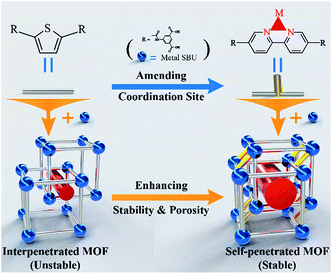
In this study, one such rare example is reported. By inserting additional coordinating sites (here through the introduction of bipyridine groups) in the backbone of the organic ligand, a two-fold interpenetrated framework [Ni2L1(μ2-H2O)(H2O)2(DMF)2]·(solvents)n (denoted as NKU-112, NKU-Nankai University, DMF = N,N′-dimethylformamide, H4L1 = 5,5′-((thiophene-2,5-dicarbonyl)bis(azanediyl))diisophthalic acid, shown in Fig. S1†) can be turned into a self-interpenetrated framework [Co2L2(μ2-H2O)(H2O)2]·(solvents)n (denoted as NKU-113, H4L2 = 5,5′-([2,2′-bipyridine]-5,5′-dicarbonyl)bis(azanediyl) diisophthalic acid, Fig. S1†), in which the extent of the mutual framework interaction is significantly increased in comparison with the two-fold interpenetrated MOF (Fig. 1). As a result, NKU-113 displays enhanced porosity and stability with respect to NKU-112, although they have similar cage-based packing structures (Scheme 1). This work provides a unique strategy for the enhancement of coordination interactions for increasing the stability and porosity of penetrated MOFs.
Results and discussion
Structures of NKU-112 and NKU-113
A solvothermal reaction of Ni(NO3)2·6H2O and H4L1 in DMF and acetonitrile affords crystals of NKU-112, whereas crystals of NKU-113 are obtained from the solvothermal reaction of Co(NO3)2·6H2O and H4L2 in DMF, acetonitrile and H2O. The structures of NKU-112 and NKU-113 were determined using single-crystal X-ray diffractometry. The bulk samples of NKU-112 and NKU-113 were characterized using IR (Fig. S2†), and their phase purities were verified by the well matched powder X-ray diffraction (PXRD) patterns of the as-synthesized samples and the simulated ones (Fig. 2). Thermogravimetric (TG) analyses showed that NKU-112 can retain its original structure up to a temperature of 370 °C, whereas NKU-113 can retain its structure up to 400 °C (Fig. S3†).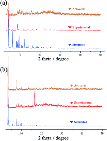 | ||
| Fig. 2 The PXRD patterns of simulated, experimental and activated samples of NKU-112 (a) and NKU-113 (b). | ||
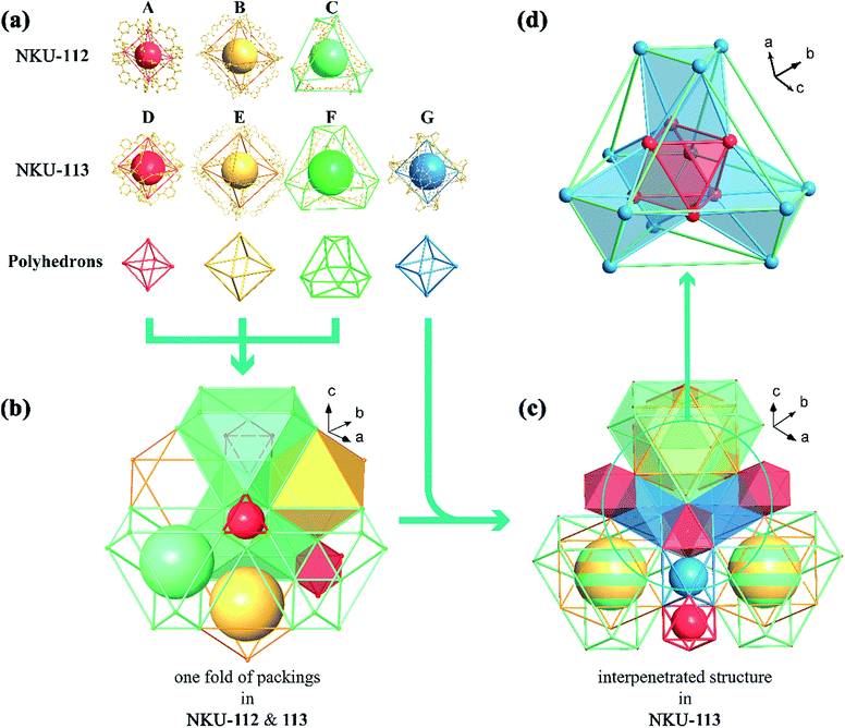
Single crystal X-ray diffraction reveals that NKU-112 crystallises in the cubic space group Ia![[3 with combining macron]](https://www.rsc.org/images/entities/char_0033_0304.gif) . Apart from the guest molecules, the asymmetric unit contains two Ni2+ cations, one L14− anion, three water and two DMF molecules. The Ni1 is six coordinated in a distorted octahedron geometry with four carboxylate oxygen atoms (O1, O15, O22 and O24) from four different organic ligands, one oxygen atom (O3) from a terminal water molecule and one oxygen atom (O13) from a μ2-water molecule. In contrast, the coordination sphere of Ni2 includes two carboxylate oxygen atoms (O23 and O25), two oxygen atoms from terminal DMF molecules (O9 and O29), one oxygen atom from a terminal water molecule (O8) and one oxygen atom from a μ2-water molecule (O13), which can also be described as a distorted octahedral geometry (Fig. S4†). Ni1 and Ni2 are bridged by two carboxylate groups and one μ2-H2O molecule to form a discrete [Ni2(COO)4(μ2-H2O)(H2O)2(DMF)2] cluster in which a water molecule is inserted between the Ni2+ ions, and the Ni1–O13–Ni2 angle is close to 120° (117.463° to be precise), a completely different value to that of a classical [M2(COO)4O2] SBU (Fig. S5†). The SBUs were further expanded by the organic linker to form a three-dimensional (3D) network. Careful examination of the network structure reveals that the framework is composed of three different types of cage. As shown in Fig. 1, the octahedral cage A, with a diameter of ca. 6.8 Å, is defined by six Ni clusters, each being at a vertex of the octahedron, and twelve isophthalate moieties along the edges. The other octahedral cage B, with a diameter of ca. 21.6 Å, is composed of six Ni clusters and twelve organic ligands, whilst the third type of cage, the distorted cuboctahedral cage C with a diameter of ca. 15.8 Å, consists of twelve Ni clusters and six organic ligands (Fig. 1b). As for the packing of NKU-112, each distorted cuboctahedral C cage is surrounded by four A cages and four B cages. Cage C shares three Ni clusters and one isophthalic moiety on the truncated surface with cage A, and three Ni clusters and L14− with cage B (Fig. 3a). Topologically, since cage A occupies vertices of cage B and C, cage A can be regarded as nodes for clarity and the framework features a uninodal 12-connected net, which is classified as fcu as determined using TOPOS software (Fig. S6a†).7 Due to the large void in the network, two-fold interpenetration occurs in NKU-112, and the solvent-accessible volume of the interpenetrated NKU-112 is estimated to be 45.7% per unit cell by PLATON.8
. Apart from the guest molecules, the asymmetric unit contains two Ni2+ cations, one L14− anion, three water and two DMF molecules. The Ni1 is six coordinated in a distorted octahedron geometry with four carboxylate oxygen atoms (O1, O15, O22 and O24) from four different organic ligands, one oxygen atom (O3) from a terminal water molecule and one oxygen atom (O13) from a μ2-water molecule. In contrast, the coordination sphere of Ni2 includes two carboxylate oxygen atoms (O23 and O25), two oxygen atoms from terminal DMF molecules (O9 and O29), one oxygen atom from a terminal water molecule (O8) and one oxygen atom from a μ2-water molecule (O13), which can also be described as a distorted octahedral geometry (Fig. S4†). Ni1 and Ni2 are bridged by two carboxylate groups and one μ2-H2O molecule to form a discrete [Ni2(COO)4(μ2-H2O)(H2O)2(DMF)2] cluster in which a water molecule is inserted between the Ni2+ ions, and the Ni1–O13–Ni2 angle is close to 120° (117.463° to be precise), a completely different value to that of a classical [M2(COO)4O2] SBU (Fig. S5†). The SBUs were further expanded by the organic linker to form a three-dimensional (3D) network. Careful examination of the network structure reveals that the framework is composed of three different types of cage. As shown in Fig. 1, the octahedral cage A, with a diameter of ca. 6.8 Å, is defined by six Ni clusters, each being at a vertex of the octahedron, and twelve isophthalate moieties along the edges. The other octahedral cage B, with a diameter of ca. 21.6 Å, is composed of six Ni clusters and twelve organic ligands, whilst the third type of cage, the distorted cuboctahedral cage C with a diameter of ca. 15.8 Å, consists of twelve Ni clusters and six organic ligands (Fig. 1b). As for the packing of NKU-112, each distorted cuboctahedral C cage is surrounded by four A cages and four B cages. Cage C shares three Ni clusters and one isophthalic moiety on the truncated surface with cage A, and three Ni clusters and L14− with cage B (Fig. 3a). Topologically, since cage A occupies vertices of cage B and C, cage A can be regarded as nodes for clarity and the framework features a uninodal 12-connected net, which is classified as fcu as determined using TOPOS software (Fig. S6a†).7 Due to the large void in the network, two-fold interpenetration occurs in NKU-112, and the solvent-accessible volume of the interpenetrated NKU-112 is estimated to be 45.7% per unit cell by PLATON.8
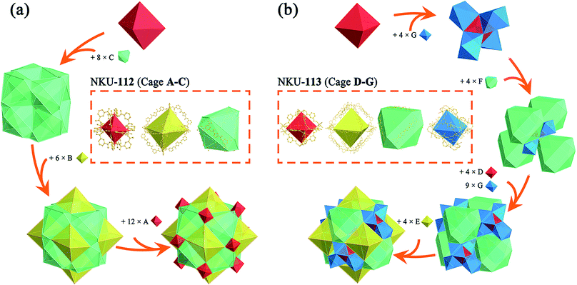 | ||
| Fig. 3 Structure combination diagrams of the cages presented in NKU-112 (a) and NKU-113 (b). Inset: coordination structures of cages A–G. | ||
The transformation between interpenetrated and self-penetrated MOFs has been studied in the past.9 After specific connecting components are added, two or more folds of interpenetrated frameworks are covalently linked to each other to form a single framework. If these components are removed, the framework can be restored to its original topology. The self-penetrated structure can also be constructed using elaborate ligand design, and the key is finding a suitable ligand. Typically, as two major coordination groups, carboxylate groups and N-containing heterocyclic groups are employed in the majority of MOF constructions.10 Among the various groups, a chelating bipyridine moiety could form a relatively stable coordination structure with a metal center to stabilize the SBU. Accordingly, a bipyridine group was selected to be inserted in the backbone of the organic ligand H4L1, and the resulting H4L2 ligand was used to construct NKU-113.
Single-crystal X-ray diffraction reveals that NKU-113 crystallises in the cubic space group Fd![[3 with combining macron]](https://www.rsc.org/images/entities/char_0033_0304.gif) m. The asymmetric unit comprises two Co2+ cations, one L24− anion, and three water molecules. Co1 and Co2 are connected to each other through a bridge comprising two carboxylate groups from L24− and a μ2-water molecule. Co1 is coordinated by four L24− anions and two water molecules in a distorted trigonal bipyramid defined by O4, O5 and four O1 atoms from four L24− anions. Co2 is coordinated by two carboxyls from L24−, two nitrogen atoms from L24− and two water molecules that together form another distorted trigonal bipyramid defined by two O2 atoms, two N1 atoms, O5 and O6 (Fig. S2†). These two metal ions are coordinated by the nitrogen atoms of L24−, featuring a different scenario to that of the Ni cluster in NKU-112 (Fig. S5†). The ligand in NKU-113 has two-fold disorder with an occupancy of 0.5 each, and Co2 has four-fold disorder with an occupancy of 0.25 each. There are four kinds of cages in NKU-113: the octahedron cage D, with a diameter of ca. 10.6 Å, is defined by six Co clusters on the vertices and twelve isophthalic moieties in L24−; octahedral cage E, with a diameter of ca. 28.6 Å, is defined by six Co clusters and twelve L24− ligands; distorted cuboctahedral cage F features four triangles combined with three Co clusters on the cross-section and six L24− on the edge, and distorted octahedron cage G with a diameter of ca. 22.0 Å, which has no corresponding structure in NKU-112, defined by six Co clusters and six L24− ligands (Fig. 1a and 3b). As for the packing mode of NKU-113, each distorted cuboctahedral cage F is surrounded by four octahedral D cages by sharing three Co clusters and three isophthalic moieties on the surface; it is additionally surrounded by twelve distorted octahedral G cages by sharing two Co clusters and half of an L24− ligand on the edge of the cross-section. Half of the F cages wrap one octahedral E cage, with the other half of the F cages wrapping four G cages and a D cage (Fig. 1d and S7†). Cages D and E & F possess two kinds of pores: a smaller pore in the range of 0.5–0.9 nm in cage D, and a larger pore in the range of 1.9–4.5 nm in cage E & F. Benefiting from the presence of the coordinating bipyridine moiety in the backbone of the L24− ligand, the pyridine group bonds to a different cluster in the framework of NKU-113, resulting in the formation of a self-penetrated structure. Accordingly, the tiling structure of the framework of NKU-113 also changed with respect to that of NKU-112 because of its self-support property (Fig. S6b†). Topologically, by regarding cage D as nodes, the framework of NKU-113 could be simplified as a 3D binodal (3,18)-connected net with a point symbol of (42·6)6(460·693), as determined by the TOPOS software. The solvent-accessible volume of NKU-113 is estimated by PLATON to be 67.2% per unit cell.
m. The asymmetric unit comprises two Co2+ cations, one L24− anion, and three water molecules. Co1 and Co2 are connected to each other through a bridge comprising two carboxylate groups from L24− and a μ2-water molecule. Co1 is coordinated by four L24− anions and two water molecules in a distorted trigonal bipyramid defined by O4, O5 and four O1 atoms from four L24− anions. Co2 is coordinated by two carboxyls from L24−, two nitrogen atoms from L24− and two water molecules that together form another distorted trigonal bipyramid defined by two O2 atoms, two N1 atoms, O5 and O6 (Fig. S2†). These two metal ions are coordinated by the nitrogen atoms of L24−, featuring a different scenario to that of the Ni cluster in NKU-112 (Fig. S5†). The ligand in NKU-113 has two-fold disorder with an occupancy of 0.5 each, and Co2 has four-fold disorder with an occupancy of 0.25 each. There are four kinds of cages in NKU-113: the octahedron cage D, with a diameter of ca. 10.6 Å, is defined by six Co clusters on the vertices and twelve isophthalic moieties in L24−; octahedral cage E, with a diameter of ca. 28.6 Å, is defined by six Co clusters and twelve L24− ligands; distorted cuboctahedral cage F features four triangles combined with three Co clusters on the cross-section and six L24− on the edge, and distorted octahedron cage G with a diameter of ca. 22.0 Å, which has no corresponding structure in NKU-112, defined by six Co clusters and six L24− ligands (Fig. 1a and 3b). As for the packing mode of NKU-113, each distorted cuboctahedral cage F is surrounded by four octahedral D cages by sharing three Co clusters and three isophthalic moieties on the surface; it is additionally surrounded by twelve distorted octahedral G cages by sharing two Co clusters and half of an L24− ligand on the edge of the cross-section. Half of the F cages wrap one octahedral E cage, with the other half of the F cages wrapping four G cages and a D cage (Fig. 1d and S7†). Cages D and E & F possess two kinds of pores: a smaller pore in the range of 0.5–0.9 nm in cage D, and a larger pore in the range of 1.9–4.5 nm in cage E & F. Benefiting from the presence of the coordinating bipyridine moiety in the backbone of the L24− ligand, the pyridine group bonds to a different cluster in the framework of NKU-113, resulting in the formation of a self-penetrated structure. Accordingly, the tiling structure of the framework of NKU-113 also changed with respect to that of NKU-112 because of its self-support property (Fig. S6b†). Topologically, by regarding cage D as nodes, the framework of NKU-113 could be simplified as a 3D binodal (3,18)-connected net with a point symbol of (42·6)6(460·693), as determined by the TOPOS software. The solvent-accessible volume of NKU-113 is estimated by PLATON to be 67.2% per unit cell.
Compared with NKU-112, the structure deployment in NKU-113 causes several changes. The SBU in NKU-112, with a formula of [Ni2(COO)4(μ2-H2O)(H2O)2DMF2], is similar to that of [Co2(COO)4(μ2-H2O)(H2O)2] in NKU-113 except for the fact that in the latter cluster the chelating bipyridine moiety in the L24− ligand replaces the coordinating DMF molecules (Fig. S5†). Furthermore, because of the additional coordination of the bipyridine moiety to the metal cluster, NKU-113 features an additional octahedral cage composed of six L24− ligands and six metal clusters (Fig. 1a) with respect to NKU-112. It is known that the coordination of solvent molecules will diminish the rigidity and stability of SBUs, and therefore replacing these coordinated solvent molecules with coordinate bonds between the SBU and the framework can strengthen the overall structure.
In detail, if Co–N bonds in NKU-113 are ignored, the packing mode of the two frameworks is different from that in NKU-112. By regarding cage A and cage D as nodes and other ligands as linkers, one structure can be simplified into an fcc-like framework (Fig. S8†). Cages A & D construct tetrahedral and octahedral voids. In NKU-112, the second framework occupies the centres of larger octahedral voids. In contrast, the second framework occupies the centers of smaller tetrahedral voids in NKU-113 (Fig. S9 and S10†). This structure change is induced by the presence of new coordination bonds since the smaller tetrahedral voids are suitable for the linking of the penetrated framework through Co–N bonds. According to the changes in packing mode, the nestification mode in NKU-113 has also varied (Fig. S11 and S12†). The presence of additional coordinate bonds causes a reduction of the distance between the two structures, which contributes to the increase in porosity and stability observed in NKU-113 with respect to NKU-112. In summary, although NKU-112 and NKU-113 have similar building blocks, the insertion of linkers in the latter is associated with obvious differences that lead to an enhancement in the structure stability and porosity.
Stabilities and adsorption properties of NKU-112 and NKU-113
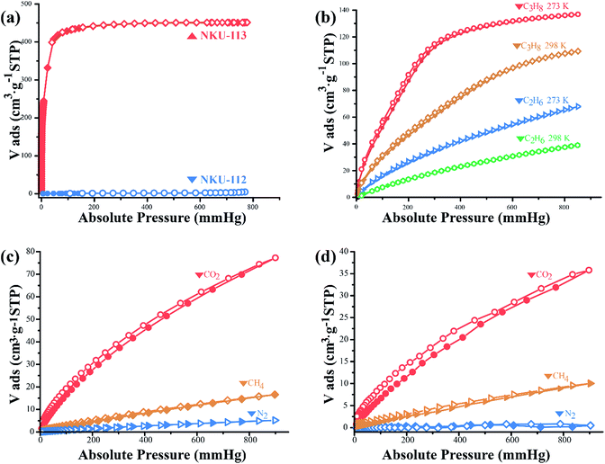
To evaluate the porosity and gas storage/separation potential of NKU-112 and NKU-113, gas adsorption experiments have been performed. Before the measurements, the samples of NKU-112 and NKU-113 were soaked in ethanol for solvent exchange and supercritically dried using carbon dioxide. However, the framework of NKU-112 partially collapsed after the activation procedures (Fig. 2a), and NKU-113 showed a well retained framework structure (Fig. 2b). It should be noted that the collapse of NKU-112 can be ascribed to the loss of coordinated solvents during activation in the SBU as discussed above.N2 sorption tests were first conducted at 77 K to characterize the porosity of the materials (Fig. 4a). The N2 adsorption isotherm of NKU-113 has the typical characteristics of a type I profile, and the Brunauer–Emmett–Teller (BET) surface area and Langmuir surface area are 1486 m2 g−1 and 1966 m2 g−1, respectively. The pore distribution analysis performed using the Horvath–Kawazoe (H–K) method shows a main distribution of 0.7–1.2 nm and 1.9–4.2 nm (Fig. S13†), indicating that two kinds of pore existed in the framework, which is consistent with the crystal structures.
Considering the highly porous framework of NKU-113 and the presence of amide groups which may benefit its gas sorption performance, a series of sorption tests were performed with C2H6, C3H8, CO2, and CH4 (Fig. 4b–d). The gas uptake of NKU-113 at 273 K is 16 cm3 g−1 (STP) for CH4, 63 cm3 g−1 (STP) for C2H6, 135 cm3 g−1 (STP) for C3H8 and 77 cm3 g−1 (STP) for CO2. At 298 K, the framework shows gas uptakes of 10 cm3 g−1 (STP) for CH4, 36 cm3 g−1 (STP) for C2H6, 105 cm3 g−1 (STP) for C3H8, and 36 cm3 g−1 (STP) for CO2. On the basis of the investigation of capacities, the heat of sorption of different gases was also investigated (Fig. S14†). The initial heat of sorption values are 15.4 kJ mol−1 for CH4, 28.2 kJ mol−1 for C2H6, 27.2 kJ mol−1 for C3H8 and 30.4 kJ mol−1 for CO2. The considerable uptakes and heat of adsorption values of NKU-113 towards alkanes and CO2 suggest its potential in gas storage and separation applications.
Conclusions
In summary, through the tuning of coordination sites in organic ligands, interpenetrated MOF NKU-112 and self-penetrated MOF NKU-113 have been constructed. Owing to the additional chelating bipyridine coordination sites introduced through the ligand, the NKU-113, featuring a self-penetrated framework, reveals enhanced stability and porosity compared with those of the interpenetrated framework of NKU-112. The approach reported herein may provide a valuable method for the stability and gas sorption performance enhancement of penetrated MOFs.Conflicts of interest
There are no conflicts to declare.Acknowledgements
This work was supported by the NSFC (91622111, 21421001, and 21531005), the 973 Program of China (2014CB845601), and the NSF of Tianjin (16JCZDJC36900). The authors are grateful to Dr Ya-Bing He for his valuable suggestions.References
- (a) L. B. Sun, J. R. Li, W. Lu, Z. Y. Gu, Z. Luo and H. C. Zhou, J. Am. Chem. Soc., 2012, 134, 15923–15928 CrossRef CAS PubMed; (b) H. Li, M. Eddaoudi, M. O’Keeffe and O. M. Yaghi, Nature, 1999, 402, 276–279 CrossRef CAS; (c) D. S. Zhang, Z. Chang, Y. F. Li, Z. Y. Jiang, Z. H. Xuan, Y. H. Zhang, J. R. Li, Q. Chen, T. L. Hu and X.-H. Bu, Sci. Rep., 2013, 3, 3312 CrossRef PubMed; (d) J. R. Li, D. J. Timmons and H. C. Zhou, J. Am. Chem. Soc., 2009, 131, 6368–6369 CrossRef CAS PubMed; (e) Q. Gao, J. Xu, D. Cao, Z. Chang and X.-H. Bu, Angew. Chem., Int. Ed., 2016, 55, 15027–15030 CrossRef CAS PubMed; (f) F. Bu, Q. Lin, Q. Zhai, L. Wang, T. Wu, S. T. Zheng, X. Bu and P. Feng, Angew. Chem., Int. Ed., 2012, 51, 8538–8541 CrossRef CAS PubMed; (g) L. Li, R.-B. Lin, R. Krishna, X. Wang, B. Li, H. Wu, J. Li, W. Zhou and B. Chen, J. Am. Chem. Soc., 2017, 139, 7733–7736 CrossRef CAS PubMed; (h) X. Cui, K. Chen, H. Xing, Q. Yang, R. Krishna, Z. Bao, H. Wu, W. Zhou, X. Dong, Y. Han, B. Li, Q. Ren, M. J. Zaworotko and B. Chen, Science, 2016, 353, 141–144 CrossRef CAS PubMed; (i) M. Bosch, S. Yuan, W. Rutledge and H.-C. Zhou, Acc. Chem. Res., 2017, 50, 857–865 CrossRef CAS PubMed.
- (a) G. Barin, G. W. Peterson, V. Crocellà, J. Xu, K. A. Colwell, A. Nandy, J. A. Reimer, S. Bordiga and J. R. Long, Chem. Sci., 2017, 8, 4399–4409 RSC; (b) P. Z. Moghadam, J. F. Ivy, R. K. Arvapally, A. M. dos Santos, J. C. Pearson, L. Zhang, E. Tylianakis, P. Ghosh, I. W. H. Oswald, U. Kaipa, X. Wang, A. K. Wilson, R. Q. Snurr and M. A. Omary, Chem. Sci., 2017, 8, 3989–4000 RSC; (c) K. Manna, T. Zhang, F. X. Greene and W. B. Lin, J. Am. Chem. Soc., 2015, 137, 2665–2673 CrossRef CAS PubMed; (d) Y. Wang, H. Cui, Z.-W. Wei, H.-P. Wang, L. Zhang and C.-Y. Su, Chem. Sci., 2017, 8, 775–780 RSC; (e) J. Liu, P. K. Thallapally, B. P. McGrail, D. R. Brown and J. Liu, Chem. Soc. Rev., 2012, 41, 2308–2322 RSC; (f) B. Chen, S. Xiang and G. Qian, Acc. Chem. Res., 2010, 43, 1115–1124 CrossRef CAS PubMed; (g) B. Aguila, Q. Sun, J. A. Perman, L. D. Earl, C. W. Abney, R. Elzein, R. Schlaf and S. Ma, Adv. Mater., 2017, 29, 1700665 CrossRef PubMed; (h) J. Park, D. Feng, S. Yuan and H.-C. Zhou, Angew. Chem.,Int. Ed., 2015, 54, 430–435 CAS; (i) W.-Y. Pei, G. Xu, J. Yang, H. Wu, B. Chen, W. Zhou and J.-F. Ma, J. Am. Chem. Soc., 2017, 139, 7648–7656 CrossRef CAS PubMed.
- (a) Z. Chang, D. H. Yang, J. Xu, T. L. Hu and X.-H. Bu, Adv. Mater., 2015, 27, 5432–5441 CrossRef CAS PubMed; (b) D. Ma, Y. Li and Z. Li, Chem. Commun., 2011, 47, 7377–7379 RSC; (c) H. Babaei, A. J. H. McGaughey and C. E. Wilmer, Chem. Sci., 2017, 8, 583–589 RSC.
- (a) X. Wang, W.-Y. Gao, J. Luan, L. Wojtas and S. Ma, Chem. Commun., 2016, 52, 1971–1974 RSC; (b) T. Wu, L. Shen, M. Luebbers, C. Hu, Q. Chen, Z. Ni and R. I. Masel, Chem. Commun., 2010, 46, 6120–6122 RSC; (c) V. Colombo, S. Galli, H. J. Choi, G. D. Han, A. Maspero, G. Palmisano, N. Masciocchi and J. R. Long, Chem. Sci., 2011, 2, 1311–1319 RSC; (d) D. Tian, Q. Chen, Y. Li, Y. H. Zhang, Z. Chang and X. H. Bu, Angew. Chem., Int. Ed., 2014, 53, 837–841 CrossRef CAS PubMed; (e) G. Chang, B. Li, H. Wang, T. Hu, Z. Bao and B. Chen, Chem. Commun., 2016, 52, 3494–3496 RSC; (f) A. Kumar, D. G. Madden, M. Lusi, K.-J. Chen, E. A. Daniels, T. Curtin, J. J. Perry and M. J. Zaworotko, Angew. Chem., Int. Ed., 2015, 54, 14372–14377 CrossRef CAS PubMed; (g) K. Tan, S. Zuluaga, E. Fuentes, E. C. Mattson, J.-F. Veyan, H. Wang, J. Li, T. Thonhauser and Y. J. Chabal, Nat. Commun., 2016, 7, 13871 CrossRef CAS PubMed.
- (a) D. Banerjee, H. Wang, Q. Gong, A. M. Plonka, J. Jagiello, H. Wu, W. R. Woerner, T. J. Emge, D. H. Olson, J. B. Parise and J. Li, Chem. Sci., 2016, 7, 759–765 RSC; (b) S. Yuan, Y.-P. Chen, J.-S. Qin, W. Lu, L. Zou, Q. Zhang, X. Wang, X. Sun and H.-C. Zhou, J. Am. Chem. Soc., 2016, 138, 8912–8919 CrossRef CAS PubMed; (c) Y. Chen, L. Wojtas, S. Ma, M. J. Zaworotko and Z. Zhang, Chem. Commun., 2017, 53, 8866–8869 RSC; (d) K.-J. Chen, D. G. Madden, T. Pham, K. A. Forrest, A. Kumar, Q.-Y. Yang, W. Xue, B. Space, J. J. Perry, J.-P. Zhang, X.-M. Chen and M. J. Zaworotko, Angew. Chem., Int. Ed., 2016, 55, 10268–10272 CrossRef CAS PubMed; (e) X.-Z. Song, C. Qin, W. Guan, S.-Y. Song and H.-J. Zhang, New J. Chem., 2012, 36, 877–882 RSC.
- S. Ma, X.-S. Wang, D. Yuan and H.-C. Zhou, Angew. Chem., Int. Ed., 2008, 47, 4130–4133 CrossRef CAS PubMed.
- V. A. Blatov, A. P. Shevchenko and D. M. Proserpio, Cryst. Growth Des., 2014, 14, 3576–3586 CAS.
- L. J. Farrugia, J. Appl. Crystallogr., 2012, 45, 849–854 CrossRef CAS.
- (a) Q. Chen, Z. Chang, W. C. Song, H. Song, H. B. Song, T. L. Hu and X.-H. Bu, Angew. Chem., Int. Ed., 2013, 52, 11550–11553 CrossRef CAS PubMed; (b) P. Shen, W.-W. He, D.-Y. Du, H.-L. Jiang, S.-L. Li, Z.-L. Lang, Z.-M. Su, Q. Fu and Y.-Q. Lan, Chem. Sci., 2014, 5, 1368–1374 RSC.
- (a) J. R. Li, A. A. Yakovenko, W. Lu, D. J. Timmons, W. Zhuang, D. Yuan and H. C. Zhou, J. Am. Chem. Soc., 2010, 132, 17599–17610 CrossRef CAS PubMed; (b) S. T. Zheng, T. Wu, B. Irfanoglu, F. Zuo, P. Feng and X. Bu, Angew. Chem., Int. Ed., 2011, 50, 8034–8037 CrossRef CAS PubMed; (c) T. F. Liu, L. Zou, D. Feng, Y. P. Chen, S. Fordham, X. Wang, Y. Liu and H. C. Zhou, J. Am. Chem. Soc., 2014, 136, 7813–7816 CrossRef CAS PubMed.
Footnotes |
| † Electronic supplementary information (ESI) available: Experimental section, crystallographic tables, IR, TG and characterization details. CCDC 1576271 and 1576272. For ESI and crystallographic data in CIF or other electronic format see DOI: 10.1039/c7sc04192f |
| ‡ Authors R. Feng and Y.-Y. Jia contributed equally to this work. |
| This journal is © The Royal Society of Chemistry 2018 |

