 Open Access Article
Creative Commons Attribution 3.0 Unported Licence
The mechanism of directed Ni(II)-catalyzed C–H iodination with molecular iodine†
Brandon E.
Haines
 a,
Jin-Quan
Yu
b and
Djamaladdin G.
Musaev
 *a
*a
aCherry L. Emerson Centre for Scientific Computation, Emory University, 1515 Dickey Drive, Atlanta, Georgia 30322, USA. E-mail: dmusaev@emory.edu
bDepartment of Chemistry, The Scripps Research Institute, 10550 North Torrey Pines Road, La Jolla, California 92037, USA
First published on 28th November 2017
Abstract
The density functional theory method is used to elucidate the elementary steps of Ni(II)-catalyzed C(sp2)–H iodination with I2 and substrates bearing N,N′-bidentate directing centers, amide-oxazoline (AO) and 8-aminoquinoline (AQ). The relative stability of the lowest energy high- and low-spin electronic states of the catalyst and intermediates is found to be an important factor for all of the steps in the reaction. As a result, two-state reactivity for these systems is reported, where the reaction is initiated on the triplet surface and generates a high energy singlet nickelacycle. It is shown that the addition of Na2CO3 base to the reaction mixture facilitates C–H activation. The presence of I2 in the reaction provides the much needed driving force for the C–H activation and nickelacycle formation and ultimately reacts to form a new C–I bond through either a redox neutral electrophilic cleavage (EC) pathway or a one-electron reductive cleavage (REC) pathway. The previously proposed Ni(II)/Ni(IV) and homolytic cleavage pathways are found to be higher in energy. The nature of the substrate is found to have a large impact on the relative stability of the lowest electronic states and on the stability of the nickelacycle resulting from C–H activation.
Introduction
Catalytic C–H functionalization—defined as the catalytic transformation of C–H bonds into C–B, C–C, C–N, C–O, C–S and C–halogen bonds—has inherent advantages for the development of environmentally friendly and sustainable synthetic routes to complex organic targets.1–7 Currently, many of the developments in this field rely on the use of expensive and rare noble metal catalysts, such as Au,8–10 Pt,11,12 Pd,13,14 Rh,5,15–18 and Ir.6,18,19 Therefore, the development of cost-effective earth-abundant transition metal catalysts (such as Fe, Co, Ni and Cu) is an attractive strategy to further capitalize on the sustainable potential of catalytic C–H functionalization.20–22 However, first-row transition metals, compared with their heavier analogues, suffer from (a) more complex reactivity (i.e. more accessible oxidation states and intermediates) due to their tendency to be involved in single-electron redox processes along with two-electron redox processes23 and (b) a lack of a driving force for insertion into C–H bonds because the resulting M–C and M–H bonds are weak.24 Thus, innovative approaches are necessary to design earth-abundant transition metal catalysts for C–H functionalization.Existing strategies in this field of scientific research employ photoredox25–28 or chelation assisted (i.e. directing group, DG, assisted)29–47 approaches. These studies have unambiguously demonstrated the effectiveness of substrates with two chelating centers, such as 8-aminoquinoline (AQ), picolinamide (PA) and others, to direct the C–H activation event.48,49 It is believed that the bidentate coordination of the substrate to the metal center provides stability to the pre-reaction complex and brings the activated C–H bond in close proximity to the transition metal center.50,51 Furthermore, these studies have identified the utmost importance of controlling the multitude of oxidation states of the transition metal centers in the course of the reaction, which may proceed via numerous pathways such as: (a) a two-electron redox pathway (i.e. oxidative addition and reductive elimination), (b) a single-electron oxidation/reduction pathway (for example, via reactive organic radical intermediate formation) and (c) redox neutral pathways.23
Several recently reported computational studies have supported the above-mentioned complexity of Ni(II)-catalyzed C–H functionalization reactions. Omer and Liu have shown that while the C(sp2)–H and C(sp3)–H bond cleavage of substrates with an 8-aminoquinoline (AQ) group by Ni(II)-catalyst occurs via the concerted metalation–deprotonation (CMD) mechanism,52,53 the mechanism of the subsequent C–C and C–X bond formation steps depends on the nature of the substrate and the coordination environment of the metal. They may occur via either radical mechanisms (involving Ni(III) complexes) when the coupling partners are substrates with steric hindrance and low X–Y/X bonding energies, such as dicumyl peroxide (O–O bond), heptafluoroisopropyl iodide (3° alkyl C–I bond) and diphenyl disulfide (S–S bond), or via an oxidative addition/reductive elimination mechanism involving a Ni(IV) intermediate when the coupling partners are phenyl iodide (aryl C–I bond) and n-butyl bromide (1° alkyl C–Br bond).54 Sunoj and coworkers also report that aryl iodides react through a Ni(II)/Ni(IV) mechanism with C(sp3)–H AQ substrates, where the regioselectivity is determined by the reductive elimination step.55 Importantly, they demonstrate that the modeling of additives in the reaction can have a large impact on the computed pathways. Thus, the nature of the coupling partners (oxidants), transition metal centers and additives, as well as both the nature and number of chelating centers, are vital for C–H functionalization using first-row transition metal catalysts.
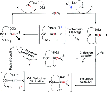
C–H iodination with molecular I2 under mild experimental conditions is a highly desirable process because it utilizes inexpensive I2 as the sole oxidant and increases the accessibility of synthetically valuable aryl halide compounds. The design of the first-row transition metal catalysts for this reaction is expected to be even more challenging because of the amphiphilic or “chameleon” nature of the I2 molecule, which can act as either an electron-donor (L-type) or electron-acceptor (Z-type) ligand in transition metal complexes.56–58 As a major advancement in this field, the Ni(II)-catalyzed C–H iodination of an AQ substrate with I2 with N,N′-directing groups was recently reported by both Chatani and coworkers59 and Koley and coworkers60 (Fig. 1). However, the mechanism of this reaction has not yet been studied in detail. Koley and coworkers proposed that either Ni(II)/Ni(IV) or redox-neutral Ni(II)/Ni(II) mechanisms could be operative (Fig. 2). In contrast, Chatani and coworkers settled on a Ni(II)/Ni(III) redox cycle that was previously proposed by Sanford and coworkers61,62 for C–Br bond formation from the reaction of Br2 and Ni(II)(phpy)(Br)(pic), where phpy = 2-phenylpyridine and pic = 2-picoline. A notable computational study by Hall and coworkers predicted a Ni(II)/Ni(III) spin-crossover mechanism for the C–Ni bromination reaction.63
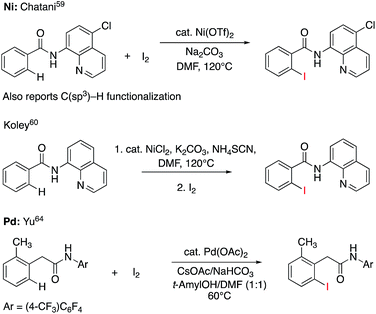 | ||
| Fig. 1 Recent representative developments in Ni(II)- and analogous Pd(II)-catalyzed C–H iodination reactions with I2 as the sole oxidant. | ||
To deal with the mechanistic complexity of Ni(II)-catalyzed C–H iodination with I2, the knowledge acquired from the analogous Pd(II)-catalyzed reaction64 could be useful, despite known differences in the electronic structure and reactivity of the Ni(II) and Pd(II) species.65,66 In their seminal work, Yu and coworkers used a commercially available monodentate acidic amide DG for the Pd(II)-catalyzed reaction,64 as opposed to the N,N′-bidentate directing groups used for the Ni-catalyzed reaction (Fig. 1). Our following extensive computational study56 of this reaction revealed that C–I bond formation proceeds via a redox-neutral electrophilic cleavage (EC) mechanism initiated by the coordination of I2 as a Z-type ligand57,67,68 to the axial position of the square-planar d8 Ar–Pd(II) C–H activation intermediate.56 Its two-electron Pd(II)/Pd(IV) oxidation mechanism, including (a) I–I oxidative addition to the Ar–Pd(II) intermediate and (b) C–I reductive elimination from the resulting Pd(IV) intermediate, is less favorable.69–71 In addition, recently we have shown that the presence of a mono-N-protected amino acid ligand (MPAA) changes the mechanism by enabling the oxidation of the Pd(II) center by I2 prior to C–H activation.72
With this uncertainty surrounding the mechanism, its importance for first-row transition metal catalyst design and the available knowledge in the literature, here we use computational methods to explore the possible mechanisms and governing factors of Ni(II)-catalyzed C–H bond iodination by molecular I2 for substrates with N,N′-bidentate chelating groups, amide-oxazoline (AO) and AQ substrates (see Fig. 3). One should note that the AO ligand, developed in the Yu group, was previously used successfully for Cu-catalyzed C–H functionalization.73–77 Here, we chose a common Ni(II) source, Ni(OAc)2, as a model catalyst because we aim to answer general questions about the reactivity of Ni(II) catalysts in C–H activation and iodination with I2. It is recognized that the identity of the pre-catalyst and the mechanism for entering the catalytic cycle are critical aspects of a successful reaction, but this is not the major focus of this study. Therefore, we do not strive for direct correlation with all of the successful experimental reaction conditions but instead focus on the general conclusions for how the catalyst achieves the critical C–H activation and iodination steps.
In general, the results of this study align with those reported by Liu54 and Sunoj55 but the reactivity of I2 and the redox neutral EC pathway were not previously studied computationally. Furthermore, the previously reported studies50,51,54,55 did not fully elaborate on the impact of the lowest-lying electronic states of the catalyst and intermediates in the mechanism. Therefore, here, for the first time in the literature, we carefully analyze the impact of the lowest-lying singlet and triplet electronic states in Ni-catalyzed C–H functionalization. It is expected that this fundamental understanding of Ni-catalyzed C–H iodination reactions and the comparison of the acquired knowledge with that from the previously studied Pd-catalyzed reaction will enhance our ability to design cost-effective and environmentally friendly Ni-catalyzed C–H functionalization reactions and open new avenues for the design of first-row transition metal catalysts for C–H halogenation.
Results and discussion
Ni(II)-catalyzed C–H iodination of the amide oxazoline (AO) substrate with I2
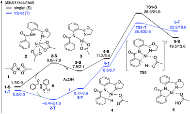 | ||
| Fig. 4 The singlet (black) and triplet (blue) free energy surfaces for the C–H bond activation of the AO substrate starting from the Ni(OAc)2 catalyst. Energies are reported as ΔG/ΔH in kcal mol−1. | ||
The first CMD process (i.e. the deprotonation of the amide, which was not calculated) and the subsequent dissociation of acetic acid completes the bidentate coordination of the substrate to the Ni center with its two chelating N-groups. In the resulting (AO-k2-N,N′,CH)Ni(II)(OAc) complex, 3, the ortho-C–H bond of the phenyl group in the substrate is closely positioned to the Ni center. Subsequently, cleavage of this ortho-C–H bond by the second acetate ligand through the CMD transition state, TS1, leads to the formation of the nickelacycle (AO-k3-N,N′,C)Ni(II)(AcOH), 5, with two Ni–N bonds and one Ni–C bond. C–H bond deprotonation at the transition state TS1 is found to be the rate-limiting step of the process and occurs with a 31.8 kcal mol−1 free energy barrier (on the triplet state PES). Since the ground electronic state of TS1 is a triplet state, but that of nickelacycle 5 is a singlet state, it is most likely that the singlet and triplet surfaces of the reaction cross after the triplet state C–H activation transition state. Thus, this process involves two lower-lying electronic states of the reactants, intermediates and transition states (i.e. shows two-state reactivity78). Thus, the formation of nickelacycle 5 is endergonic by 25.9 kcal mol−1 (Fig. 4).
The computed thermodynamic instability of the nickelacycle (AO-k3-N,N′,C)Ni(II)(AcOH) relative to reactants Ni(OAc)2 (triplet) + AO is consistent with a previous computational study on the oxidative addition of C–H bonds to Ni(0) complexes.79 This is also consistent with the deuterium labeling experiments performed by Chatani and coworkers,59 the experiments of Koley and coworkers demonstrating that the nickelacycle formed by C–H activation cannot be isolated in the absence of I2,60 as well as the computational findings by Chen50,51 and Liu.54 Additional support for this conclusion comes from the fact that nickelacycles achieved via C–H activation are rare in the literature.80 This is in contrast to analogous Pd-catalyzed reactions, where the palladacycles resulting from C–H activation are thermodynamically stable and can often be isolated, characterized and used as pre-catalysts.81–83 Thus, based on the results given above, we once again highlight one of the foremost difficulties for Ni(II)-catalyzed C–H functionalization as the lack of a thermodynamic driving force for C–H activation,84 which is a major reason for the failure of the isolation and characterization of nickelacycles from C–H activation processes. Of course, in the presence of an oxidant/electrophile, for example I2, the C–H formation barrier (i.e. the reverse barrier for C–H activation) is expected to compete with either I–I bond activation (if the reaction proceeds via an oxidative addition mechanism) and/or C–I bond formation (if the reaction proceeds via an electrophilic addition mechanism) and/or radical formation barriers. These processes are discussed in the next section.
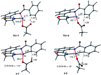
As shown in Fig. 5, the electronic state of the system has a significant impact not only on the energetics but also on the geometry of the C–H activation transition states and products. The most striking difference is in the angle of the acetate base relative to the substrate coordination plane: in the triplet structures, TS1-T and 5-T, the acetate is nearly perpendicular to the substrate coordination plane (N–Ni-OAc = 104.8° and 99.4°, respectively), whereas in the singlet structures, TS1-S and 5-S, the acetate is in the plane of the substrate (N–Ni-OAc = 167.4° and 174.1°, respectively). It is also noted that the AO substrate is capable of twisting slightly away from planarity (in 5-T, C–N–N–Ni = −14°), which may allow for some stabilization of the transition state toward the tetrahedral geometry favored on the triplet surface.63
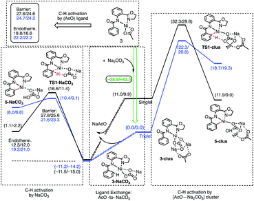
The results presented in Fig. 6 show that the addition of the Na2CO3 molecule to complex 3 leads to the formation of (AO-k2-N,N′,CH)Ni(II)(OAc⋯Na2CO3), (3-clus) “(AcO⋯Na2CO3)-cluster-complex” (see ESI, Fig. S1,† for selected geometries); the calculated free energy of the reaction (AO-k2-N,N′,CH)Ni(II)(OAc) + Na2CO3 → (AO-k2-N,N′,CH)Ni(II)(OAc⋯Na2CO3) is −28.9 kcal mol−1. This complex has a triplet ground electronic state with 1.61|e| alpha-spin density on the Ni centers. Its open-shell singlet state (with an 〈S2〉 value of 0.63) is 11.0 kcal mol−1 higher in free energy. From the triplet “cluster-complex” 3-clus, the reaction may proceed either via C–H bond activation through the CMD triplet transition state TS1-clus by the (AcO⋯Na2CO3) ligand, or via ligand-exchange (i.e. NaOAc dissociation) where the subsequent C–H bond activation requires almost no barrier (we were not able to locate the associated transition state) and is exergonic by 11.5 kcal mol−1. Thus, one may confidently conclude that the addition of a Na2CO3 molecule to the reaction mixture will produce AcO-to-NaCO3 ligand exchange and will generate the new catalytically active species (AO-k2-N,N′,CH)Ni(II)(NaCO3). In this newly generated active species, C–H bond activation requires a 21.6 kcal mol−1 free energy barrier and is endergonic by 12.3 kcal mol−1. A comparison of these energy parameters for active species (AO-k2-N,N′,CH)Ni(II)(NaCO3) with those for (AO-k2-N,N′,CH)Ni(II)(OAc) (calculated relative to 3-T), a 24.7 kcal mol−1 free energy barrier and 18.8 kcal mol−1 endergonicity, clearly demonstrates the benefits of the presence of Na2CO3 in the reaction conditions. This is consistent with the findings of Liu and coworkers that a Ni(NaCO3)2·4DMF catalyst is the likely active catalyst in their systems.54 To summarize, the addition of Na2CO3 to the reaction mixture (a) generates the new catalytically active species (AO-k2-N,N′,CH)Ni(II)(NaCO3) with a small or no energy barrier, (b) reduces the rate-limiting C–H activation barrier by 3.1 kcal mol−1 and (c) stabilizes the C–H activation product by 6.3 kcal mol−1.
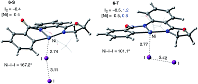
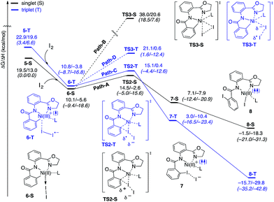
Consistently, the triplet electronic state of the I2 coordination complex (6-T) becomes only 0.7 kcal mol−1 higher in free energy than its singlet state counterpart 6-S. Analysis of unpaired spin densities (with 1.2|e| and 0.8|e| on the I2 and Ni fragments, respectively) allows us to characterize 6-T as a Ni(III)–I2 complex formed by one electron transfer from the Ni center to I2 (the calculated Mulliken charges of the I2 and Ni fragments are −0.5|e| and 0.5|e|, respectively).63 As a result of this full (rather than partial) Ni-to-I2 electron transfer, the elongation of the I–I bond (3.42 Å) becomes more pronounced than in 6-S and the ∠Ni–I–I angle becomes bent (101.1°).
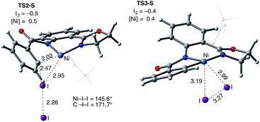
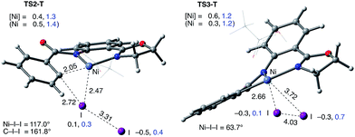
The accessibility of the triplet state complex 6-T upon single electron transfer from Ni to I2 makes the reactivity of the nickelacycle with I2 more complex than that of its Pd analogue. Indeed, as illustrated in Fig. 8, one can expect two distinct iodination pathways for each of the singlet and triplet state complexes 6-S and 6-T. For the singlet 6-S complex, the pathways are analogous to those studied for the Pd-catalyzed reaction: (A) a redox neutral Ni(II)/Ni(II) pathway proceeding through the concerted electrophilic cleavage (EC) of I2 and concomitant C–I bond formation (black solid line in Fig. 8) and (B) a Ni(II)/Ni(IV) pathway proceeding through I–I oxidative addition (OA) followed by C–I reductive elimination (black dashed line in Fig. 8). For the triplet state 6-T complex, these pathways are (C) a single electron reductive electrophilic cleavage (REC) Ni(III)/Ni(II) process in which C–I bond formation and the one electron reduction of the Ni(III) center occur simultaneously (blue solid line in Fig. 8), and (D) a radical mechanism (RA) in which cleavage of the I–I bond forms a Ni(III) complex and iodine atom (blue dashed line in Fig. 8). It is possible that these pathways can interconvert into each other by crossing between the singlet and triplet surfaces. Below, we discuss these processes in more detail (for the sake of simplicity, the free energies discussed in this section are calculated relative to the singlet state complex 6-S).
With the expulsion of I− during the reaction, we also investigated the role of I3− complex formation in the presence of excess I2. We compute I3− formation from I2 and I− to be exergonic by 12.3 kcal mol−1. This suggests that I3− complex formation could be playing the role of providing additional driving force for I− generation. Indeed, coordination of an additional molecule of I2 to complexes 7-S and 7-T to form 7-S-I3 and 7-T-I3, respectively are exergonic by 15.6 and 13.0 kcal mol−1, respectively. Thus, we propose that the EC and REC pathways can be facilitated by I3− formation.
In summary, consideration of several reaction pathways for Ni–C bond iodination with I2 reveals that the redox neutral Ni(II)/Ni(II) electrophilic cleavage (EC) and Ni(II)/Ni(III) single electron reductive electrophilic cleavage (REC) pathways are the most likely mechanisms for this reaction. The computed barrier for the EC pathway is the lowest for the AO substrate, but the computed barrier for the REC pathway is only 0.6 kcal mol−1 higher. The previously studied 2-electron Ni(II)/Ni(IV) oxidative addition/reductive elimination (OA) and Ni(II)/Ni(III) radical (RA, homolytic cleavage) pathways are found to be higher in energy for I2. Given that the reactivity is highly dependent on the identity of the oxidant/electrophile, these results suggest that the EC and REC pathways should also be considered for Ni-catalyzed C–H functionalization reactions.
Ni(II)-catalyzed C–H iodination of 8-aminoquinoline (AQ) substrate with I2
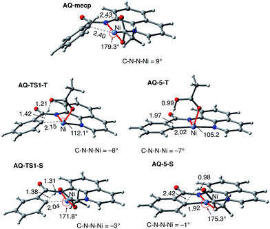
To provide further validation and connection to experiments, we also studied the Ni(II)-catalyzed C–H bond iodination of the AQ substrate with I2. We believe that our calculated results are going to be helpful in understanding and rationalizing experimental findings by Chatani59 and Koley,60 as well as in the prediction of novel ligands. In general, we find that the AQ substrate gives qualitatively the same results as the AO substrate with a few interesting differences that will be discussed here briefly. Full details of the calculations with the AQ substrate can be found in the ESI (see Fig. S3†).Firstly, as shown in the calculated potential energy surface in Fig. 11, the C–H activation of the AQ substrate by Ni(OAc)2 requires an overall 33.8 kcal mol−1 free energy barrier (calculated relative to the triplet complex AQ-2-T) at the transition state AQ-TS1-S, which is ca. 2 kcal mol−1 larger than that reported for the AO substrate (Fig. 4). In contrast to the AO substrate, the rate-limiting C–H activation transition state for the AQ substrate, AQ-TS1-S, has a singlet ground electronic state; its triplet state counterpart AQ-TS1-T lies 2.3 kcal mol−1 higher. Thus, the singlet-triplet surface crossing likely occurs before the rate-limiting C–H activation transition state for the AQ substrate. Indeed, we were able to locate a minimum energy crossing point (AQ-mecp) that is close in energy (13.0 kcal mol−1) and geometry to the singlet reactant structure AQ-4-S (Fig. 11 and 12). The nature of the substrate also has a significant impact on the stability of the nickelacycles resulting from the C–H activation. As mentioned above, for the AO substrate, the overall process, Ni(OAc)2 (triplet) + AO → 5-S, is endergonic by 19.5 kcal mol−1. In contrast, this process for the AQ substrate, i.e. the Ni(OAc)2 (triplet) + AQ → AQ-5-S reaction, is endergonic only by 13.6 kcal mol−1.
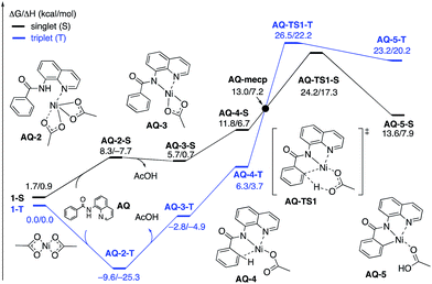 | ||
| Fig. 11 The singlet (black) and triplet (blue) free energy surfaces for C–H bond activation in the AQ substrate by a Ni(OAc)2 catalyst. The energies are reported as ΔG/ΔH in kcal mol−1. | ||
Thus, the replacement of the AO substrate by the AQ substrate (a) shifts the C–H bond activation reaction to the singlet surface and the triplet-to-singlet surface crossing occurs before the C–H activation transition state, (b) makes the overall process thermodynamically more favorable by 5.9 kcal mol−1 and (c) only slightly (ca. 2 kcal mol−1) increases the rate-limiting C–H activation barrier. The thermodynamic preference of the C–H activation in AQ compared to AO can be explained by the careful analysis of the geometries in the corresponding final products. Indeed, nickelacycle AQ-5-S has a square planar geometry with a ∠(Ni–N–N–C) angle of −1° through the formation of a fused [3.3.0] ring system (Fig. 12), whereas the nickelacycle 5-S is more twisted out of plane (Ni–N–N–C = −6°) because of additional ring strain introduced by the larger [4.3.0] fused ring system (Fig. 6). This analysis is consistent with the findings of Chen and coworkers.50,51
Secondly, in contrast to the AO substrate, for the AQ substrate the triplet I2-coordination complex AQ-6-T, which lies 4.7 kcal mol−1 higher than reactants AQ-1-T + I2, is slightly lower (by 0.5 kcal mol−1) than its singlet counterpart AQ-6-S (see ESI, Fig. S3†). Likewise, the Ni(II)/Ni(III) single electron reductive electrophilic cleavage (REC) free energy barrier (Path-C, initiated from the AQ-6-T complex) at the transition state AQ-TS2-T is calculated to be lower than the redox neutral Ni(II)/Ni(II) electrophilic cleavage (EC) free energy barrier (Path-A, initiated from the AQ-6-S complex and following via the transition state AQ-TS2-S). Based on these results, it appears that the C–H iodination reaction in the AQ substrate will revert back to the triplet surface much earlier on the reaction coordinate (i.e. during I2 coordination) than that was the case with the AO substrate. However, like the AO substrate, the Ni(II)/Ni(III) single electron reductive electrophilic cleavage (REC) and redox neutral Ni(II)/Ni(II) electrophilic cleavage (EC) pathways remain close in energy for the AQ substrate. This suggests that one can switch between the substrate structures (or reaction conditions) and still achieve C–I bond formation. Significantly, these data clearly demonstrate the importance of the availability of the lowest-lying electronic states of the first-row transition metal centers for C–H iodination in substrates with an N,N′-bidentate chelating groups: the actual mechanism of the reaction directly relates to stability and the energy difference between lowest high- and low-spin electronic states.
Conclusions
Extensive calculations on the elementary steps of Ni(II)-catalyzed C–H iodination with I2 and two substrates with N,N′-bidentate directing groups (AO and AQ) have revealed the most likely reaction mechanism as illustrated in Fig. 13.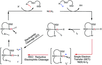 | ||
| Fig. 13 The mechanism proposed for Ni-catalyzed C–H iodination with I2 based on the DFT calculations in this study. | ||
Importantly, we found the relative stability of the lowest energy high- and low-spin electronic states to be an important factor for all of the steps in the reaction. We expect this to be a general feature of first-row transition metal catalysts in C–H functionalization. We found that:
(1) The reaction is initiated by substrate coordination to the triplet Ni(OAc)2 complex and N–H deprotonation to form a stable triplet (SUB-k2-N,N′,CH)Ni(II)(OAc) complex. The calculated stabilization energies are 6.4 and 9.6 kcal mol−1 for the AO and AQ substrates, respectively.
(2) From (SUB-k2-N,N′,CH)Ni(II)(OAc), C–H activation occurs via the base-assisted CMD mechanism on either the triplet surface (for the AO substrate) or the singlet surface (for the AQ substrate) and generates singlet Ni(II)-nickelacycles. This process requires a significant free energy barrier (31.8 kcal mol−1 for AO and 33.8 kcal mol−1 for AQ), occurs via triplet-to-singlet spin crossover and is endergonic by 19.5 kcal mol−1 for AO and 13.6 kcal mol−1 for AQ. Thus, in the absence of an oxidant (or coupling partners) this C–H activation process is not feasible, which is consistent with experiments.60
(3) However, in the presence of I2 as an oxidant, the coordination of I2 to Ni(II)-nickelacycle provides additional stability to the C–H activation product. In both the singlet and triplet states of the resulting nickelacycle–I2 complex 6, I2 accepts electron density from the Ni complex. Since in the triplet state nickelacycle–I2 complex 6-T almost one electron is transferred to I2, it was characterized as a [Ni(III)+–I2−] ion pair complex.
(4) The subsequent C–I bond formation is very fast through either the redox-neural EC pathway, if the reaction starts from the singlet 6-S complex, or the one-electron REC pathway, if the reaction starts from the triplet 6-T complex. Both pathways lead to the formation of a stable, high spin Ni(II)–I intermediate.
(5) The addition of basic Na2CO3 to the reaction mixture initiates AcO-to-NaCO3 ligand exchange and generates the (SUB-k2-N,N′,CH)Ni(II)(NaCO3) active catalyst. This ligand exchange reaction is exergonic for the AO substrate and requires an insignificant energy barrier. Furthermore, the involvement of a new base, i.e. Na2CO3, reduces the rate-limiting C–H activation barrier by 3.1 kcal mol−1 and stabilizes the C–H activation product by 6.3 kcal mol−1. These findings are consistent with experiments, showing that Na2CO3 helps facilitate Ni-catalyzed C–H iodination with I2.59,60
(6) The replacement of the AO substrate by the AQ substrate affects the energy difference between the lowest high- and low-spin electronic states of the systems in several places along the reaction pathway. It makes the C–H activation step thermodynamically more favorable by 5.9 kcal mol−1 and only slightly (ca. 2 kcal mol−1) increases the rate-limiting C–H activation barrier. Thus, the computations indicate that the AO substrate is also viable for Ni(II)-catalyzed C–H iodination with I2.
Computational details
The calculations were performed with the Gaussian 09 (G09) program.93 The geometry optimizations and frequency calculations for all of the reported structures were performed at the B3LYP-D3/[6-31G(d,p) + Lanl2dz (Pd, I)] level of theory with the corresponding Hay–Wadt effective core potential for Pd and I,94–96 and Grimme’s empirical dispersion-correction (D3) for B3LYP.97 Each reported minimum has zero imaginary frequencies and each transition state (TS) structure has only one imaginary frequency. Intrinsic reaction coordinate (IRC) calculations were performed for selected transition state structures to confirm their identity. Bulk solvent effects were incorporated for all of the calculations using the self-consistent reaction field polarizable continuum model (IEF-PCM)98–100 with dimethylsulfoxide (DMSO) as the solvent. The calculated Gibbs free energies were corrected to a solution standard state of 1 M at room temperature (298.15 K).101,102It is known that Ni-complexes may have several energetically close lower-lying electronic states,63 therefore, here we investigated both the ground and first excited states of the reactants, intermediates, transition states and products of the reaction. Some of the structures on the singlet potential energy surface had lower energy open-shell singlet electronic states. In these cases, we re-calculated the geometries and energies of the structures at their open-shell singlet electronic states using unrestricted DFT (UB3LYP-D3).103,104 The minimum energy crossing points (MECP) between singlet and triplet states were located using the MECPro program (v. 1.0.3) developed by Ess and coworkers105 with G09.
Conflicts of interest
There are no conflicts to declare.Acknowledgements
This work was supported by the National Science Foundation under the CCI Center for Selective C–H Functionalization (CHE-1700982). We gratefully acknowledge the NSF MRI-R2 grant (CHE-0958205 for D. G. M.) and the use of the resources of the Cherry Emerson Center for Scientific Computation. We also thank Dr R. Roszak for helpful discussions and Prof. D. H. Ess (BYU) for providing access to his MECPro code (v. 1.0.3).Notes and references
- L. Ackermann, Chem. Rev., 2011, 111, 1315–1345 CrossRef CAS PubMed.
- T. Bruckl, R. D. Baxter, Y. Ishihara and P. S. Baran, Acc. Chem. Res., 2012, 45, 826–839 CrossRef CAS PubMed.
- K. M. Engle, T. S. Mei, M. Wasa and J. Q. Yu, Acc. Chem. Res., 2012, 45, 788–802 CrossRef CAS PubMed.
- K. Godula and D. Sames, Science, 2006, 312, 67–72 CrossRef CAS PubMed.
- H. M. L. Davies and J. R. Manning, Nature, 2008, 451, 417–424 CrossRef CAS PubMed.
- J. F. Hartwig, J. Am. Chem. Soc., 2016, 138, 2–24 CrossRef CAS PubMed.
- C. J. Li and B. M. Trost, Proc. Natl. Acad. Sci. U. S. A., 2008, 105, 13197–13202 CrossRef CAS PubMed.
- A. Arcadi, Chem. Rev., 2008, 108, 3266–3325 CrossRef CAS PubMed.
- T. de Haro and C. Nevado, Synthesis, 2011, 2530–2539, DOI:10.1055/s-0030-1260122.
- J. Xie, C. D. Pan, A. Abdukader and C. J. Zhu, Chem. Soc. Rev., 2014, 43, 5245–5256 RSC.
- M. Lersch and M. Tilset, Chem. Rev., 2005, 105, 2471–2526 CrossRef CAS PubMed.
- S. S. Stahl, J. A. Labinger and J. E. Bercaw, Angew. Chem., Int. Ed., 1998, 37, 2181–2192 CrossRef CAS.
- X. Chen, K. M. Engle, D. H. Wang and J. Q. Yu, Angew. Chem., Int. Ed., 2009, 48, 5094–5115 CrossRef CAS PubMed.
- T. W. Lyons and M. S. Sanford, Chem. Rev., 2010, 110, 1147–1169 CrossRef CAS PubMed.
- D. A. Colby, R. G. Bergman and J. A. Ellman, Chem. Rev., 2010, 110, 624–655 CrossRef CAS PubMed.
- D. A. Colby, A. S. Tsai, R. G. Bergman and J. A. Ellman, Acc. Chem. Res., 2012, 45, 814–825 CrossRef CAS PubMed.
- M. P. Doyle, R. Duffy, M. Ratnikov and L. Zhou, Chem. Rev., 2010, 110, 704–724 CrossRef CAS PubMed.
- K. Shin, H. Kim and S. Chang, Acc. Chem. Res., 2015, 48, 1040–1052 CrossRef CAS PubMed.
- I. A. I. Mkhalid, J. H. Barnard, T. B. Marder, J. M. Murphy and J. F. Hartwig, Chem. Rev., 2010, 110, 890–931 CrossRef CAS PubMed.
- H. M. L. Davies and D. Morton, J. Org. Chem., 2016, 81, 343–350 CrossRef CAS PubMed.
- A. A. Kulkarni and O. Daugulis, Synthesis, 2009, 24, 4087–4109 Search PubMed.
- B. Su, Z. C. Cao and Z. J. Shi, Acc. Chem. Res., 2015, 48, 886–896 CrossRef CAS PubMed.
- S. Z. Tasker, E. A. Standley and T. F. Jamison, Nature, 2014, 509, 299–309 CrossRef CAS PubMed.
- J. Uddin, C. M. Morales, J. H. Maynard and C. R. Landis, Organometallics, 2006, 25, 5566–5581 CrossRef CAS.
- D. R. Heitz, J. C. Tellis and G. A. Molander, J. Am. Chem. Soc., 2016, 138, 12715–12718 CrossRef CAS PubMed.
- M. H. Shaw, V. W. Shurtleff, J. A. Terrett, J. D. Cuthbertson and D. W. C. MacMillan, Science, 2016, 352, 1304–1308 CrossRef CAS PubMed.
- B. J. Shields and A. G. Doyle, J. Am. Chem. Soc., 2016, 138, 12719–12722 CrossRef CAS PubMed.
- Z. W. Zuo, D. T. Ahneman, L. L. Chu, J. A. Terrett, A. G. Doyle and D. W. C. MacMillan, Science, 2014, 345, 437–440 CrossRef CAS PubMed.
- L. C. M. Castro and N. Chatani, Chem. Lett., 2015, 44, 410–421 CrossRef CAS.
- Y. Aihara and N. Chatani, J. Am. Chem. Soc., 2013, 135, 5308–5311 CrossRef CAS PubMed.
- Y. Aihara and N. Chatani, J. Am. Chem. Soc., 2014, 136, 898–901 CrossRef CAS PubMed.
- X. F. Cong, Y. X. Li, Y. Wei and X. M. Zeng, Org. Lett., 2014, 16, 3926–3929 CrossRef CAS PubMed.
- M. L. Li, J. X. Dong, X. L. Huang, K. Z. Li, Q. Wu, F. J. Song and J. S. You, Chem. Commun., 2014, 50, 3944–3946 RSC.
- H. Shiota, Y. Ano, Y. Aihara, Y. Fukumoto and N. Chatani, J. Am. Chem. Soc., 2011, 133, 14952–14955 CrossRef CAS PubMed.
- W. F. Song, S. Lackner and L. Ackermann, Angew. Chem., Int. Ed., 2014, 53, 2477–2480 CrossRef CAS PubMed.
- X. S. Wu, Y. Zhao and H. B. Ge, J. Am. Chem. Soc., 2014, 136, 1789–1792 CrossRef CAS PubMed.
- X. S. Wu, Y. Zhao and H. B. Ge, Chem.–Eur. J., 2014, 20, 9530–9533 CrossRef CAS PubMed.
- Y. Aihara, M. Tobisu, Y. Fukumoto and N. Chatani, J. Am. Chem. Soc., 2014, 136, 15509–15512 CrossRef CAS PubMed.
- M. Iyanaga, Y. Aihara and N. Chatani, J. Org. Chem., 2014, 79, 11933–11939 CrossRef CAS PubMed.
- C. Lin, D. Y. Li, B. J. Wang, J. Z. Yao and Y. H. Zhang, Org. Lett., 2015, 17, 1328–1331 CrossRef CAS PubMed.
- Y. J. Liu, Y. H. Liu, S. Y. Yan and B. F. Shi, Chem. Commun., 2015, 51, 6388–6391 RSC.
- Y. J. Liu, Z. Z. Zhang, S. Y. Yan, Y. H. Liu and B. F. Shi, Chem. Commun., 2015, 51, 7899–7902 RSC.
- S. Maity, S. Agasti, A. M. Earsad, A. Hazra and D. Maiti, Chem.–Eur. J., 2015, 21, 11320–11324 CrossRef CAS PubMed.
- S. Y. Yan, Y. J. Liu, B. Liu, Y. H. Liu, Z. Z. Zhang and B. F. Shi, Chem. Commun., 2015, 51, 7341–7344 RSC.
- L. C. M. Castro, A. Obata, Y. Aihara and N. Chatani, Chem.–Eur. J., 2016, 22, 1362–1367 CrossRef PubMed.
- X. Yang, G. Shan, L. Wang and Y. Rao, Tetrahedron Lett., 2016, 57, 819–836 CrossRef CAS.
- T. Uemura, M. Yamaguchi and N. Chatani, Angew. Chem., Int. Ed., 2016, 55, 3162–3165 CrossRef CAS PubMed.
- V. G. Zaitsev, D. Shabashov and O. Daugulis, J. Am. Chem. Soc., 2005, 127, 13154–13155 CrossRef CAS PubMed.
- Z. Ruan, S. Lackner and L. Ackermann, Angew. Chem., Int. Ed., 2016, 55, 3153–3157 CrossRef CAS PubMed.
- H. Tang, X. R. Huang, J. N. Yao and H. Chen, J. Org. Chem., 2015, 80, 4672–4682 CrossRef CAS PubMed.
- H. Tang, B. W. Zhou, X. R. Huang, C. Y. Wang, J. N. Yao and H. Chen, ACS Catal., 2014, 4, 649–656 CrossRef CAS.
- D. Balcells, E. Clot and O. Eisenstein, Chem. Rev., 2010, 110, 749–823 CrossRef CAS PubMed.
- D. L. Davies, S. A. Macgregor and C. L. McMullin, Chem. Rev., 2017, 117, 8649–8709 CrossRef CAS PubMed.
- H. M. Omer and P. Liu, J. Am. Chem. Soc., 2017, 139, 9909–9920 CrossRef CAS PubMed.
- S. Singh, S. K and R. B. Sunoj, J. Org. Chem., 2017, 82, 9619–9626 CrossRef CAS PubMed.
- B. E. Haines, H. Y. Xu, P. Verma, X. C. Wang, J. Q. Yu and D. G. Musaev, J. Am. Chem. Soc., 2015, 137, 9022–9031 CrossRef CAS PubMed.
- M. D. P. Mingos, J. Organomet. Chem., 2014, 751, 153–173 CrossRef.
- A. Y. Rogachev and R. Hoffmann, J. Am. Chem. Soc., 2013, 135, 3262–3275 CrossRef CAS PubMed.
- Y. Aihara and N. Chatani, ACS Catal., 2016, 6, 4323–4329 CrossRef CAS.
- B. Khan, R. Kant and D. Koley, Adv. Synth. Catal., 2016, 358, 2352–2358 CrossRef CAS.
- A. T. Higgs, P. J. Zinn and M. S. Sanford, Organometallics, 2010, 29, 5446–5449 CrossRef CAS.
- A. T. Higgs, P. J. Zinn, S. J. Simmons and M. S. Sanford, Organometallics, 2009, 28, 6142–6144 CrossRef CAS.
- A. L. Renz, L. M. Perez and M. B. Hall, Organometallics, 2011, 30, 6365–6371 CrossRef CAS.
- X. C. Wang, Y. Hu, S. Bonacorsi, Y. Hong, R. Burrell and J. Q. Yu, J. Am. Chem. Soc., 2013, 135, 10326–10329 CrossRef CAS PubMed.
- F. S. Han, Chem. Soc. Rev., 2013, 42, 5270–5298 RSC.
- K. Wu and A. G. Doyle, Nat. Chem., 2017, 9, 779–784 CrossRef CAS PubMed.
- A. Amgoune and D. Bourissou, Chem. Commun., 2011, 47, 859–871 RSC.
- J. Bauer, H. Braunschweig and R. D. Dewhurst, Chem. Rev., 2012, 112, 4329–4346 CrossRef CAS PubMed.
- L. Canovese, F. Visentin and C. Santo, J. Organomet. Chem., 2014, 770, 6–13 CrossRef CAS.
- A. J. Canty, M. C. Denney, B. W. Skelton and A. H. White, Organometallics, 2004, 23, 1122–1131 CrossRef CAS.
- M. J. Zhou, T. L. Yang and L. Dang, J. Org. Chem., 2016, 81, 1006–1020 CrossRef CAS PubMed.
- R. E. Plata, D. E. Hall, B. E. Haines, D. G. Musaev, L. Chu, D. P. Hickey, M. S. Sigman, J. Q. Yu and D. G. Blackmond, J. Am. Chem. Soc., 2017, 139, 9238–9245 CrossRef CAS PubMed.
- M. Shang, S. Z. Sun, H. X. Dai and J. Q. Yu, Org. Lett., 2014, 16, 5666–5669 CrossRef CAS PubMed.
- M. Shang, S. Z. Sun, H. L. Wang, B. N. Laforteza, H. X. Dai and J. Q. Yu, Angew. Chem., Int. Ed., 2014, 53, 10439–10442 CrossRef CAS PubMed.
- M. Shang, H. L. Wang, S. Z. Sun, H. X. Dai and J. Q. Yu, J. Am. Chem. Soc., 2014, 136, 11590–11593 CrossRef CAS PubMed.
- S. Z. Sun, M. Shang, H. L. Wang, H. X. Lin, H. X. Dai and J. Q. Yu, J. Org. Chem., 2015, 80, 8843–8848 CrossRef CAS PubMed.
- H. L. Wang, M. Shang, S. Z. Sun, Z. L. Zhou, B. N. Laforteza, H. X. Dai and J. Q. Yu, Org. Lett., 2015, 17, 1228–1231 CrossRef CAS PubMed.
- D. Schroder, S. Shaik and H. Schwarz, Acc. Chem. Res., 2000, 33, 139–145 CrossRef CAS PubMed.
- M. Reinhold, J. E. McGrady and R. N. Perutz, J. Am. Chem. Soc., 2004, 126, 5268–5276 CrossRef CAS PubMed.
- L. S. Jongbloed, D. Garcia-Lopez, R. van Heck, M. A. Siegler, J. J. Carbo and J. I. van der Vlugt, Inorg. Chem., 2016, 55, 8041–8047 CrossRef CAS PubMed.
- I. P. Beletskaya and A. V. Cheprakov, J. Organomet. Chem., 2004, 689, 4055–4082 CrossRef CAS.
- J. Dupont, C. S. Consorti and J. Spencer, Chem. Rev., 2005, 105, 2527–2571 CrossRef CAS PubMed.
- A. Shiota and H. C. Malinakova, J. Organomet. Chem., 2012, 704, 9–16 CrossRef CAS PubMed.
- S. A. Johnson, Dalton Trans., 2015, 44, 10905–10913 RSC.
- Q. Q. Lu, H. Z. Yu and Y. Fu, J. Am. Chem. Soc., 2014, 136, 8252–8260 CrossRef CAS PubMed.
- M. Lafrance, C. N. Rowley, T. K. Woo and K. Fagnou, J. Am. Chem. Soc., 2006, 128, 8754–8756 CrossRef CAS PubMed.
- B. Lian, L. Zhang, G. A. Chass and D. C. Fang, J. Org. Chem., 2013, 78, 8376–8385 CrossRef CAS PubMed.
- C. Mateos, J. Mendiola, M. Carpintero and J. M. Minguez, Org. Lett., 2010, 12, 4924–4927 CrossRef CAS PubMed.
- H. Y. Sun, S. I. Gorelsky, D. R. Stuart, L. C. Campeau and K. Fagnou, J. Org. Chem., 2010, 75, 8180–8189 CrossRef CAS PubMed.
- S. Rousseaux, S. I. Gorelsky, B. K. W. Chung and K. Fagnou, J. Am. Chem. Soc., 2010, 132, 10692–10705 CrossRef CAS PubMed.
- T. M. Figg, M. Wasa, J. Q. Yu and D. G. Musaev, J. Am. Chem. Soc., 2013, 135, 14206–14214 CrossRef CAS PubMed.
- H. Y. Xu, K. Muto, J. Yamaguchi, C. Y. Zhao, K. Itami and D. G. Musaev, J. Am. Chem. Soc., 2014, 136, 14834–14844 CrossRef CAS PubMed.
- M. J. Frisch, G. W. Trucks, H. B. Schlegel, G. E. Scuseria, M. A. Robb, J. R. Cheeseman, G. Scalmani, V. Barone, B. Mennucci, G. A. Petersson, H. Nakatsuji, M. Caricato, X. Li, H. P. Hratchian. A. F. Izmaylov, J. Bloino, G. Zheng, J. L. Sonnenberg, M. Hada, M. Ehara, K. Toyota, R. Fukuda, J. Hasegawa, M. Ishida, T. Nakajima, Y. Honda, O. Kitao, H. Nakai, T. Vreven, J. A. Montgomery Jr, J. E. Peralta, F. Ogliaro, M. Bearpark, J. J. Heyd, E. Brothers, K. N. Kudin, V. N. Staroverov, R. Kobayashi, J. Normand, K. Raghavachari, A. Rendell, J. C. Burant, S. S. Iyengar, J. Tomasi, M. Cossi, N. Rega, M. J. Millam, M. Klene, J. E. Knox, J. B. Cross, V. Bakken, C. Adamo, J. Jaramillo, R. Gomperts, R. E. Stratmann, O. Yazyev, A. J. Austin, R. Cammi, C. Pomelli, J. W. Ochterski, R. L. Martin, K. Morokuma, V. G. Zakrzewski, G. A. Voth, P. Salvador, J. J. Dannenberg, S. Dapprich, A. D. Daniels, Ö. Farkas, J. B. Foresman, J. V. Ortiz, J. Cioslowski and D. J. Fox, Gaussian 09, Revision D.01, Gaussian, Inc., Wallingford CT, 2009 Search PubMed.
- P. J. Hay and W. R. Wadt, J. Chem. Phys., 1985, 82, 270–283 CrossRef CAS.
- P. J. Hay and W. R. Wadt, J. Chem. Phys., 1985, 82, 299–310 CrossRef CAS.
- W. R. Wadt and P. J. Hay, J. Chem. Phys., 1985, 82, 284–298 CrossRef CAS.
- S. Grimme, J. Antony, S. Ehrlich and H. Krieg, J. Chem. Phys., 2010, 132, 154104–154119 CrossRef PubMed.
- E. Cances, B. Mennucci and J. Tomasi, J. Chem. Phys., 1997, 107, 3032–3041 CrossRef CAS.
- B. Mennucci and J. Tomasi, J. Chem. Phys., 1997, 106, 5151–5158 CrossRef CAS.
- G. Scalmani and M. J. Frisch, J. Chem. Phys., 2010, 132, 114110–114124 CrossRef PubMed.
- S. Essafi, S. Tomasi, V. K. Aggarwal and J. N. Harvey, J. Org. Chem., 2014, 79, 12148–12158 CrossRef CAS PubMed.
- R. E. Plata and D. A. Singleton, J. Am. Chem. Soc., 2015, 137, 3811–3826 CrossRef CAS PubMed.
- D. J. Marell, L. R. Furan, B. P. Woods, X. Lei, A. J. Bendelsmith, C. J. Cramer, T. R. Hoye and K. T. Kuwata, J. Org. Chem., 2015, 80, 11744–11754 CrossRef CAS PubMed.
- L. F. Zou, R. S. Paton, A. Eschenmoser, T. R. Newhouse, P. S. Baran and K. N. Houk, J. Org. Chem., 2013, 78, 4037–4048 CrossRef CAS PubMed.
- L.-A. Hamill, J. D. Snyder and D. H. Ess, MECPro Version 1.0.3: Minimum Energy Crossing Program, 2016 Search PubMed.
Footnote |
| † Electronic supplementary information (ESI) available: Additional geometrical information and free energy surfaces for the examined reaction pathways and computed energies in hartree for all reported structures. Cartesian coordinates for all reported structures are provided in xyz format (Struct.xyz). See DOI: 10.1039/c7sc04604a |
| This journal is © The Royal Society of Chemistry 2018 |

