 Open Access Article
Multicomponent metal–organic framework membranes for advanced functional composites†
Michael S.
Denny
Jr
,
Mark
Kalaj
,
Kyle C.
Bentz
 and
Seth M.
Cohen
 *
*
Department of Chemistry and Biochemistry, University of California, San Diego, La Jolla, California 92093-0358, USA. E-mail: scohen@ucsd.edu
First published on 17th September 2018
Abstract
The diverse chemical and structural properties of metal–organic frameworks (MOFs) make them attractive for myriad applications, but their native powder form is limiting for industrial implementation. Composite materials of MOFs hold promise as a means of exploiting MOF properties in engineered forms for real-world applications. While interest in MOF composites is growing, research to date has largely focused on utilization of single MOF systems. The vast number of different MOF structures provides ample opportunity to mix and match distinct MOF species in a single composite to prepare multifunctional systems. In this work, we describe the preparation of three types of multi-MOF composites with poly(vinylidene fluoride) (PVDF): (1) co-cast MOF MMMs, (2) mixed MOF MMMs, and (3) multilayer MOF MMMs. Finally, MOF MMMs are explored as catalytic membrane reactors for chemical transformations.
Introduction
Research on metal–organic frameworks (MOFs) is entering its third decade1 and significant efforts are being directed toward applied studies of these porous, crystalline materials. Steps toward utilization of MOF-based materials are underway,2–7 and recently the first MOF-based products have emerged for sale.8,9 The inherent high surface areas, tunable porosities, and diverse chemical functionalities of MOFs make their use in heterogeneous catalytic transformations an especially promising prospect.3,7,10–14 Indeed, catalysis with MOFs is of great interest,15,16 with researchers seeking to employ MOF catalysts as rapid,15,17 efficient,18,19 and selective catalysts,20 even using the pore geometry to help drive catalyst selectivity.21–23Despite the potential of MOFs for catalytic transformations, there have been two major hurdles to their implementation. First, many MOFs are relatively unstable when exposed to air, ambient humidity, or mildly caustic conditions.24 The second challenge is that MOFs typically form as microcrystalline powders. Both of these issues significantly limit the handling, operation, and processing of MOF materials for industrial scale applications. Even if the MOF catalyst is intended for use in an anaerobic system, the MOF must be shelf stable until use in the reactor, so chemical stability is a requirement. Additionally, the handling of powders in reactors presents challenges to formation and containment of the active catalyst, requiring further engineering controls in the system.
Previous work has shown that many of these issues can be overcome by fabrication of a MOF-polymer composite.25–27 Unstable MOFs can be effectively shielded from degradation by moisture through inclusion in a polymeric matrix,26 with the added benefit of being incorporated into an engineered form factor that makes their handing much easier than the native powder form. Engineered MOF composites, such as pressed pellets and mixed matrix membranes (MMMs) have become an area of increasing interest.7,14,28–30 However, compared to other inorganic materials, such as zeolites, the development of MOF-polymer composites is still in its infancy.31–33 Composites of MOFs and polymeric binders is a promising route to obtaining functional fibres, textiles, and films that exploit the extraordinary gas sorption, sensing, and catalytic properties of MOFs.
Recently, we developed a methodology to prepare a wide range of MOF composites as MMMs.25 In one example, HKUST-1 (HKUST = Hong Kong University of Science and Technology),34 a copper-based MOF, shows significantly enhanced chemical stability when fabricated into a MMM with poly(vinylidene fluoride) (PVDF) when compared to the native MOF (i.e., microcrystalline powder).26 Having thus demonstrated that the composite material can enhance the performance of MOFs, we sought to explore the ways in which multiple MOF species could be combined in a single composite material to prepare multifunctional materials. These multiple MOF materials should allow a single composite material to be used for multifunctional catalytic membranes in flow reactor systems for cascade reactions in fine or commodity chemical synthesis, or even as a single, multifunctional catalyst for degrading a variety of species in an industrial waste stream.
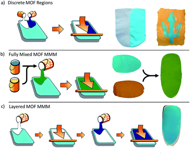
While multifunctional MOF composites are of significant interest for various applications, the specific form that the multifunctional composite takes will be highly dependent on the intended use. To this end, we have prepared a series of multi-MOF composites in various forms (Fig. 1). First, we explored combined materials wherein the MOF species are separated into discrete regions within a single composite material. Next, we prepared a range of mixed MOF MMMs, wherein the MOF species are fully integrated throughout the membrane. Finally, we developed a method to prepare layered MOF MMMs with use of a cross-linking agent to inhibit dissolution of the polymeric binder. These techniques for the combination of MOF species in a single composite material will allow for further implementation of MOF-based materials tailor made for real-world applications.
Experimental methods
General information
Starting materials and solvents were purchased and used without further purification from commercial suppliers (Sigma-Aldrich, Alfa Aesar, EMD, TCI, and others). PVDF (Kynar HSV-900) was provided by Arkema. Details of MOF syntheses and postsynthetic protocols are provided in the ESI.†MOF MMM ink formulation
Single MOF inks were prepared according to the literature procedure.25 In a typical MOF ink preparation for a 60% wt MMM, 120 mg of MOF was dispersed in 5 mL acetone with sonication for 30 min in a scintillation vial. 1.07 g of a PVDF solution (7.5% wt in DMF) was then added to the MOF suspension. The suspension was further sonicated for 30 min and then the acetone was removed by rotary evaporation, resulting in the final MOF ‘ink’.This same procedure was adapted for multiple MOF species. For example, to prepare an ink for a 60% MOF MMM containing UiO-66 and HKUST-1 in equal ratios, 60 mg UiO-66 and 60 mg HKUST-1 are dispersed together in 5 mL acetone, then treated as above. MOF ratios in the final product can be adjusted by adjusting the composition of the ink.
Crosslinked MMM ink formulation
Inks for crosslinked MOF MMMs were prepared by following the same procedure as above. Then, after removal of the acetone by rotary evaporation, 1,6-hexamethylene diamine (HMDA) was added to the ink formulation at 5 mol% relative to the PVDF monomer in the ink. For example, in the ink for preparing a 60% wt MMM described above, 8.5 μL HMDA was added to the MOF ink. The ink with HMDA added was then sonicated for 30 min to ensure homogeneity of the ink.MOF MMM fabrication
Films were cast from these MOF inks on Al foil substrates by drawdown coating using a 400 μm doctor blade at a coating speed of 25 mm s−1. The films were then heated to remove solvent (1 h in an oven at 70 °C, or 12 h at 100 °C for crosslinked MMMs). The MMMs were then delaminated from the Al substrate by immersion in CH3OH. The resulting free-standing films were dried in air prior to characterization and use.Results and discussion
Herein, three approaches to multifunctional MOF composite membranes are described: (1) co-cast MOF MMMs, (2) mixed MOF MMMs, and (3) layered MOF MMMs.Co-cast MOF MMMs
The first strategy for preparing multi-MOF composite materials involved casting inks of different MOF species into discrete regions of the same monolithic film. The result of this relatively simple strategy is a large area sample that has defined regions of each MOF type. To produce films of this type, individual inks are applied side-by-side onto the same substrate, followed by simultaneous draw-down casting such that the inks contact each other during casting and the polymer matrix is contiguous in the final film. The MOF film is then heated to drive off the casting solvent and the resultant membrane is delaminated from the substrate as previously described for single MOF MMMs.25Fig. 1a depicts the basic process and results of this strategy. The resultant films are monolithic with no obvious weakness at the seam between the MOF types. Moreover, because the inks made with different MOF types are highly viscous and have well matched surface tensions, there is not a large degree of mixing of the MOF types at the interface that would result from bleed between the two inks. The result is that the two MOF species stay well separated in discrete regions even while the polymer forms a continuous matrix between the different regions. Two of these films are shown in Fig. 1a. The film on the left is composed of a UiO-66 domain (white) and a HKUST-1 domain (right). Just as in the single MOF films, each of these domains retains the crystallinity and porosity of the MOF in the composite (Fig. S1†), while joining the two into a unified MOF MMM with a continuous polymer matrix combining the discrete regions. While this approach provides a continuous film with macroscale discrete MOF regions, there is certainly a small amount of mixing of the species at the interface, which will give a very small region with a gradient of the two MOF species. For applications with the need for extremely sharp transitions between the active MOF species, higher precision may be achieved with some modification.
A slight modification of this process allows for creation of sharp edges and more complex designs, as demonstrated in the right image in Fig. 1a. The ‘Triton’ logo of U.C. San Diego athletics was created by selectively applying HKUST-1 (blue) and MIL-53(Fe) (yellow, MIL = Material of Institute Lavoisier) to the same substrate. In this case, the doctor blade was not used to spread these inks. Instead, each ink was simply applied to selected areas of the substrate via pipette to form the pattern, analogous to painting a picture. The inks were applied sequentially to the substrate. First, the blue regions were created using an HKUST-1 ink. The sample was left to slowly dry at room temperature until it no longer flowed freely, but was still wet. The edges of the triton shape were then quickly trimmed with a scalpel to create straight, sharp edges, followed by application of the MIL-53(Fe) ink in the yellow regions. The sample was left at room temperature for 10 minutes to allow the inks to self-level and create a continuous matrix between the discrete regions, then heated to drive off the solvent and delaminated from the substrate. As above, the high viscosity and well-matched surface tensions of the inks prevent significant mixing of the MOF species between the regions. This composite sample also remains an intact monolith after solvent removal as a single MMM, bearing discrete macroscopic domains of HKUST-1 and MIL-53(Fe), evident from the distinctly colored regions. While this technique of pattern creation is somewhat crude, this process should be readily adaptable to processes like inkjet printing to apply MOFs to a substrate in complex patterns with high spatial resolution for applications like sensing arrays.
Mixed MOF MMMs
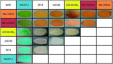
The second approach to producing integrated composites with multiple MOF functionalities produced fully mixed MOF species within the MMMs. In this type of MMM, two or more MOF species are fully mixed throughout the membrane without any obvious separation of the species. Fabrication of these mixed MOF MMMs is similar to production of the single MOF MMMs. To prepare these MMMs, a mixed MOF ink is prepared (see Experimental methods). This ink is then cast and heated to remove solvent. Fig. 1b depicts this process and shows the result of a MMM produced from an ink containing MIL-53(Fe)35 and HKUST-1.34In Fig. 1b, single MOF MMMs are shown on the left, where the HKUST-1 MMM is blue and the MIL-53(Fe) MMM is orange. The mixed MOF MMM is green, as would be expected from mixing these two colors, showing evidence of good integration of the two species at the macroscale. This process is versatile and can be applied to a variety of mixed MOF MMMs (Fig. 2). Moreover, just as in the single MOF system, the total MOF content is easily tailored in the ink formulation up to approximately 70% wt, above which the films become too brittle for significant handling.
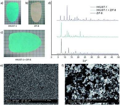
Closer examination of these MMM films shows that the characteristics of the component MOFs remain intact, just as in the single MOF systems. Fig. 3 shows photographs of MMMs of: (a) HKUST-1, (b) ZIF-8, (c) the mixed MOF MMM, (d) their corresponding PXRD spectra, and (e and f) SEM images of the MMM. The total MOF content of each film is 60% wt with equal parts (30% wt each) of HKUST-1 and ZIF-8 in the mixed MOF MMM. The mixed MOF MMM is easily handled and macroscopically behaves the same as the single MOF systems.
The mixed HKUST-1 and ZIF-8 MMM shows clear indication of good incorporation of both MOF components in a complementary way. The color of the film is a lighter blue than the pure HKUST-1 film, as would be expected by blending a white species with the blue species, but the HKUST-1 still demonstrates the characteristic color change (light blue to deep violet) on heating of the MMM that indicates dehydration of the HKUST-1 Cu-paddlewheel SBUs (data not shown).36
Examination of the films by PXRD shows diffraction peaks in the spectrum of the mixed MOF MMM attributable to both component MOF crystal structures (Fig. 3d). The PXRD spectrum for the mixed MOF MMM (cyan) contains peaks consistent with both the ZIF-8 MMM spectrum (black) and the HKUST-1 MMM spectrum (blue). This diffraction from both component species in the PXRD spectra is consistent across the remainder of the mixed MOF MMMs shown in Fig. 2. Water contact angle measurements were performed on both mixed MOF and layered MOF systems. In mixed MOF systems, the hydrophobicity of the MMMs lies between the contact angle values of the individual MOF MMMs, whereas in the layered MOF system each layered side behaves nearly identical to the individual MOF membranes (Fig. S18 and S19†). Dynamic mechanical analysis (DMA) was performed on MMMs at low strain (0.2%) to assess the mechanical robustness of the materials. Overall, introduction of MOF particles into PVDF films enhanced the storage moduli, with very modest increases with ZIF-8, but significant enhancement with HKUST-1 compared to pure PVDF films. The mixed and layered MMMs showed similar moduli to HKUST-1/PVDF (Table S1 and Fig. S20†). Complete characterization of these films, including PXRD and SEM, can be found in the ESI (Fig. S2–S17†).
Confirmation of good dispersion of the two MOF species in the mixed MOF MMM was obtained by SEM imaging. Fig. 3e and f show the surface of the mixed MOF film. Two distinct crystallite sizes are clearly visible: large crystals: ca. 2 μm in diameter are HKUST-1, and smaller crystals, ca. 200 nm in diameter are ZIF-8. From these images, it can be seen that there is good dispersion of the two species, without obvious separation, segregation, or self-aggregation. This same thorough integration of the mixed species holds true for the remainder of the MOF formulations shown in Fig. 2; SEM analysis can be found in the ESI (Fig. S2–S15†). BET surface area calculated from the N2 sorption isotherm of this mixed HKUST-1 and ZIF-8 MMM gives an apparent surface area of 635 m2 g−1 (Fig. S16†). This value scales well to the expected surface area for the mass of MOF in this membrane, indicating that the majority of the MOF porosity remains accessible in the mixed composite system.
Layered MOF MMMs
The third strategy employed to make multifunctional MOF MMMs, outlined in Fig. 1c, is to layer the MOF species in the MMM. Achieving intact layered MOF MMMs proved to be non-trivial. Indeed, apart from one recent report from Peterson et al.,37 there is little literature precedent for such composite materials. Utilizing PVDF as the binder matrix in a layered system presents a significant challenge resulting from the solubility characteristics of the polymer. PVDF is soluble in some high-boiling solvents, which is beneficial to the chemical stability of PVDF based systems, but effectively eliminates most common solvents from use in composite formulations, especially those that are easily removed at low temperatures.In previous work, we found that MOF inks formulated in DMF were excellent for fabricating MMMs with PVDF. The boiling point of DMF is 153 °C, so the film dries slowly unless high temperatures are used. Attempts to prepare a multi-layer MOF MMM by simply casting a second layer on top of a pre-formed MMM failed. This is because the DMF of the new MOF ink slowly solvates the PVDF of the already formed MMM. This solvation swells and ultimately, partially dissolves the PVDF of the first layer. This solvation destroys the MOF MMM, resulting in a cracked, non-continuous film. This technical hurdle was overcome by employing a crosslinking agent in the ink formulation and adjusting the fabrication procedure to limit the volume changes in the polymer due to solvation upon addition of subsequent layers.
To overcome the solvent-induced dissolution of PVDF in the MMMs, we employed diamine crosslinking of the polymer, a well-known process for strengthening fluoropolymers.38–41 The PVDF in the MMM was crosslinked via addition of a small amount of a diamine to the ink formulation prior to casting the films.38 The MOF inks were first prepared in the typical fashion: (1) the MOF was dispersed in acetone, (2) a PVDF solution in DMF was added to the MOF dispersion, (3) the mixture was sonicated to ensure homogeneity, and (4) the acetone was removed from the mixture by rotary evaporation.25 Following removal of acetone, hexamethylene diamine (HMDA) a short chain, linear diamine was added to the MOF ink and the mixture was further sonicated to ensure homogeneity. The ink was then cast into MMMs via doctor blade, and incubated for 12 h at 100 °C to achieve both removal of the casting solvent and to accelerate the reaction of HMDA with the PVDF.
Only a small amount of HMDA was needed to achieve polymer crosslinking in the MMMs made from UiO-66, UiO-66-NH2, ZIF-8, and MIL-53(Al)–NH2. 5 mol% HMDA (relative to the PVDF monomer) was sufficient to inhibit redissolution of the MMM when fully immersed in DMF for over 24 h. Evidence of PVDF crosslinking by FTIR was not observed because of the extremely small fraction of HMDA relative to both polymer and MOF in the MMM, but the resistance to dissolution provides indirect evidence that this crosslinking was successful. A MMM prepared by the same method without HMDA in the casting ink formulation disintegrated as the PVDF dissolved in DMF within 10 min (data not shown). Analysis of the crosslinked films by PXRD and SEM shows no obvious difference from the non-crosslinked MOF MMMs25 (Fig. S2–S15†). Addition of more crosslinking agent (10 mol%) to a casting ink of UiO-66 also inhibited dissolution of the MMM, but also caused the membrane to be noticeably more brittle than that prepared with 5 mol% crosslinking agent. One important caveat to this methodology is that HMDA is reactive toward HKUST-1, causing a color change in the MOF (from blue to green) and degradation of HKUST-1 crystallinity at high concentrations of HMDA. For this reason, HMDA was not added to any HKUST-1 ink formulations.
The addition of a crosslinking agent to the casting formulation noticeably enhanced the stability of the films such that a second MOF layer could be applied without destruction of the underlying MMM. However, the casting area of the second layer is limited to 1–2 cm2 when applied to a fully dried MMM. While the HMDA crosslinking successfully inhibits dissolution of the PVDF, the polymer matrix in the MMM still swells from the casting solvent upon addition of the second layer. When the second layer is limited to a small area, the volume change of the swelling polymer is limited, but over large areas, buckling of the MMM and disruption of the second layer was observed.
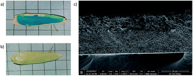
To enable casting of multi-layer films larger than 1–2 cm2, we attempted to pre-swell the MMM prior to deposition of the second layer. The first layer of the MMM was resolvated, after casting and heating, by immersion in various solvents. The solvated MMM was then laid flat on a glass plate, blotted to remove excess solvent, and the second layer was applied to the MMM via doctor blade. Solvation with low boiling solvents like acetone sufficiently swelled the MMM, but gave a short working time in which to apply the second MOF layer because of rapid evaporation. This resulted in uneven application of the second layer and insufficient quality of the final multi-layer MMM. Resolvating the MMM with a high boiling solvent like DMF, by contrast, gave a longer working time and successfully expanded the available size of the casting area to include larger area MMMs. Use of the HMDA crosslinking agent was essential in this process to ensure that the first MOF layer remained intact during the resolvation step. As discussed above, without crosslinking, resolvation with DMF would have caused the polymer in the MMM to redissolve, eliminating the integrity of the first MMM layer. Fig. 4 shows the results of using this resolvation process to achieve a two-layer MOF MMM. In this example, HKUST-1 has been cast as the second layer after solvating the crosslinked UiO-66 MMM with DMF. The SEM cross section of the MMM is shown in Fig. 4c. In this image, a clear demarcation is evident in the membrane between the smaller UiO-66 particles on the bottom and the larger HKUST-1 particles on the top half of the film.
While the SEM cross section is clean and the bilayer area of the MMM is defect free, Fig. 4a shows that the edges of the UiO-66 film deformed during the second heating step, likely due to rapid contraction of this area while heating. Ultimately this method was deemed unsatisfactory because, especially in larger areas, many of these layered MMMs showed evidence of defects (e.g., tears and buckling) after the second heating step.
Uniform deposition of multiple MOF layers was ultimately achieved by deposition of subsequent MOF inks after only a partial drying of the underlying layer. A similar methodology was independently developed in a concurrent study.37 In short, the film is dried at elevated temperature until the majority of the casting solvent is removed, but the film remains solvated, and thus has not contracted. When the second layer is then applied to this film and the composite is fully dried, the layers can dry together and contract at the same rate, so as not to buckle or tear the final film.
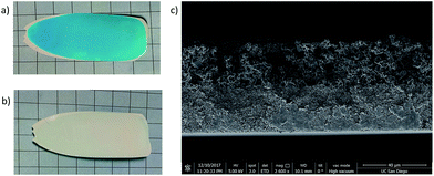
In a typical multilayer MOF MMM the MOF inks are prepared in parallel since the coating process happens quickly. The first layer is cast via the normal process and placed in a 70 °C oven for 3–5 min. During this time, the solvent front can be clearly observed in the drying film. At the point when the surface of the film takes on a matte appearance, but is still solvated, the sample is removed from the oven and the second MOF ink is cast on top of it. This process can then be repeated if subsequent layers are required. The MMM is then heated for 12 h at 100 °C to fully dry the film. Addition of HMDA as a crosslinker was used in these films to further enhance their integrity and ensure that the MOF layers are well adhered in the monolithic MMM. Fig. 5 shows the result of this process with a two layer film of ZIF-8 (white) and HKUST-1 (blue).
Fig. 5c shows a clean cross section in the SEM with a clear demarcation between the ZIF-8 layer on the bottom and the larger HKUST-1 particles on the top of the MMM. In this process, the size of the MMM is no longer limited and the MMM does not show degradation of the first layer upon deposition of the second. The squares in the underlying grid in both sets of images are 1 cm2 each, showing that the possible casting area is larger using this methodology.
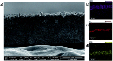
As indicated earlier, this method for creating multilayer films can be expanded to produce films with multiple subsequent layers applied on top of the first MOF layer and is not limited to two-layer films. Fig. 6 shows a cross section of a three-layer MMM fabricated from ZIF-8 (bottom), UiO-66 (middle), and HKUST-1 (top). The SEM-EDX maps for Cu, Zr, and Zn are shown in Fig. 6b–d, respectively. As seen earlier, the larger HKUST-1 particles sit on the top side of the membrane because it was final layer added to the composite. The Cu EDX map confirms this, with the Cu signal clearly localized to the top layer of the membrane, mirroring the location of the large HKUST-1 particles.
The demarcation between the ZIF-8 and UiO-66 is more difficult to discern in the cross section image because the two MOFs have similar particle sizes (ca. 100 nm), both of which are significantly smaller than the HKUST-1 particles. However, the EDX maps clearly show that the Zr-based UiO-66 is localized in the middle layer of the MMM, and the Zn-based ZIF-8 is the bottom layer, with no significant overlap between the different layers (Fig. 6).
Catalytic MOF membranes
Application of layered MOF membranes, for use in catalytic chemical transformations was explored. There is a significant body of literature exploring MOFs as heterogeneous catalysts for chemical reactions.10,15,42–44 MMMs with catalytic MOFs were prepared such that the reaction mixture was simply passed through the active MMM and the product is recovered from the eluent. A set of model reactions was chosen to demonstrate the utility of MOF MMMs as membrane reactors (Scheme 1).In the first reaction, the deprotection of benzaldehyde dimethylacetal yields benzaldehyde on reaction with water in an acid catalyzed reaction. Second, a Knoevenagel condensation between benzaldehyde and malononitrile employs a basic catalyst.45–48 The chemical diversity of MOFs allows fabrication of MMMs that are capable of catalysing these transformations as the reaction mixture transits the membrane using either a mixture of MOFs or a single, bifunctional MOF catalyst.49–52
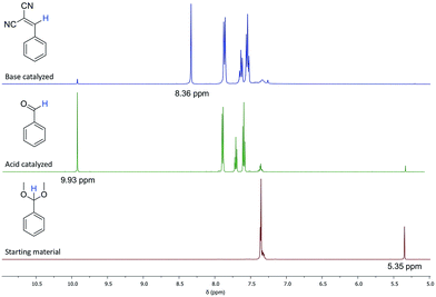
The aforementioned reactions can be followed by 1H NMR, as there is a shift in the position of the benzylic proton in each molecule shown in Scheme 1. In the benzaldehyde dimethyl acetal starting material, this proton is a singlet at 5.35 ppm (Fig. 7, red spectrum). After the acid catalysed reaction, this proton on benzaldehyde is a singlet at 9.93 ppm (Fig. 7, green spectrum). After the base catalysed reaction, the benzylic proton of the product appears as a singlet at 8.36 ppm (Fig. 7, blue spectrum).
MIL-101-NO2 was used for the acid catalysed step of this reaction,53,54 which showed good catalytic activity at elevated temperature in the catalytic membrane system. A 60% wt MIL-101-NO2 MMM was prepared with 5 mol% HMDA crosslinking agent as described above. After delamination, a 6.5 mg section (65 μm thickness) was placed in an 11 mm diameter Swinnex® syringe filter housing. The reaction solution containing 30 μL benzaldehyde dimethylacetal (0.20 mmol), 0.5 mL D2O, and 2.5 mL DMSO-d6 was then passed through the MMM at a rate of 25 μL min−1 at 55 °C. The reaction product was analysed by 1H NMR to determine the extent of conversion (Fig. S21 and 22†). The reaction shows 70% conversion of the starting material to benzaldehyde. When the reaction solution also contained 12 μL malononitrile (0.22 mmol), 42% conversion of the starting material was observed, with a mixture of products between the benzaldehyde intermediate and the final Knoevenagel condensation product.
The second reaction (Scheme 1) is the base catalysed Knoevenagel condensation of benzaldehyde with malononitrile. This is a widely studied reaction that is readily catalysed by ZIF-8 at room temperature.45,47,48,50,52 As expected from these reports, a ZIF-8 MMM (60% wt) performs well for this transformation at room temperature in the membrane reactor. A solution of benzaldehyde (20 μL, 0.20 mmol) and malononitrile (12 μL, 0.22 mmol) in 3 mL DMSO-d6 was passed through the 60% wt ZIF-8 MMM (3.5 mg MMM, 11 mm diameter disc, MMM area = 95 mm2, ∼68 μm thick) at a rate of 25 μL min−1 at room temperature. The 1H NMR shows high conversion of the starting material, with only 5% of the benzaldehyde remaining (Fig. S23†).
After demonstrating that each reaction could be successfully catalysed by a MOF MMM, the activity of both mixed and layered MMMs was tested for performing the complete reaction sequence in Scheme 1. First, a mixed MOF MMM containing 30% wt MIL-101-NO2 and 30% wt ZIF-8 was prepared (Fig. S16†). A 6.3 mg section (60 μm thickness) of this MMM was placed in the syringe filter housing and a reaction solution containing 30 μL benzaldehyde dimethylacetal (0.20 mmol), 12 μL malononitrile (0.22 mmol), 0.5 mL D2O, and 2.5 mL DMSO-d6 was passed through the MMM at a rate of 25 μL min−1 at 55 °C. The eluent was analysed by 1H NMR (Fig. S24†), which showed that the conversion of the starting material in this system is relatively low (31% conversion) compared to the MIL-101-NO2 only MMM. However, as expected, the intermediate benzaldehyde is almost completely absent from the eluent, indicating that any benzaldehyde formed was quickly converted to the final product by ZIF-8. The low conversion of the starting material is likely because this mixed MMM contains only 30% wt MIL-101-NO2, half of that in the single MOF MMM, and thus a lower catalyst loading.
Alternatively, a layered MMM was prepared from MIL-101-NO2 and ZIF-8 and a 7.2 mg section (75 μm thickness) of this MMM was placed in the syringe filter housing, such that the reaction solution would first encounter the MIL-101-NO2 layer, then the ZIF-8 layer. Again, a reaction solution containing 30 μL benzaldehyde dimethylacetal (0.20 mmol), 12 μL malononitrile (0.22 mmol), 0.5 mL D2O, and 2.5 mL DMSO-d6 was passed through the MMM at a rate of 25 μL min−1 at 55 °C. 1H NMR (Fig. S25†), showed that the conversion rate of the starting material in this system is quite high (84%) and little of the benzaldehyde intermediate remains (5%) after passing through the layered MMM, while 95% conversion is achieved to the final product.
From a system-design viewpoint, both mixed and layered MMM systems have advantages in membrane reactors. The mixed systems may be used for catalysing completely independent reactions for a mixed feed that may have a variety of components. Moreover, the fabrication process of a simple mixed MMM is simpler and provides reliable results. For cascade type reactors, where a starting material must first be converted to an intermediate and then to a final product, a layered system may ensure a higher conversion rate to the intermediate before the reaction mixture encounters the second catalyst.
These proof-of-concept experiments with catalytic mixed and layered MOF MMMs show that there is significant potential for these types of functional materials for chemical transformation. Further optimization and a more sophisticated experimental setup with better control of reaction conditions like flow rate and temperature control should allow for use of such materials in real production systems.
Conclusions
MOF-based composite materials have the potential to find utility in myriad industrial, commercial, and military applications. This potential is reflected in the ever growing research and commercial efforts on MOF-based materials. However, to fully exploit the chemical diversity of MOFs in these composite materials, methodologies for incorporation of multiple MOF species in a single composite are needed. In the work described here, we have developed methods for incorporation of multiple MOF species in co-cast, fully mixed, and layered systems that can be tailored for a specific system, based on need. We have also investigated the addition of a crosslinking agent (HMDA) to the MOF ink formulation to expand the scope of solvents compatible with these MMMs beyond what was previously possible. Finally, we have demonstrated proof-of-concept catalytic systems with MOF MMMs as one possible application of membranes of this type. These catalytic demonstrations are sufficient to show that: (1) a catalytic MOF system can be encapsulated and used in a truly heterogeneous form for adaptation to flow reaction systems, and (2) that the MOF is intimately reacting with dissolved species as they transit the membrane. Marriage of MOF membranes with highly catalytic MOFs for industrially relevant transformations has high potential to simplify flow reactor design and bring down manufacturing costs.Conflicts of interest
There are no conflicts to declare.Acknowledgements
Development of methods for fabricating MMMs was supported by the National Science Foundation, Division of Materials Research, under award number DMR-1506059 (S. M. C.). Evaluation and characterization of catalysis by MMMs was supported by the Army Research Office, Department of Army Material command, under Award No. W911NF-16-2-0106 (S.M.C.). This work was performed in part at the San Diego Nanotechnology Infrastructure (SDNI) of U.C. San Diego, a member of the National Nanotechnology Coordinated Infrastructure, which is supported by the National Science Foundation (Grant ECCS-1542148). M. K. is supported by the Department of Defense (DoD) through the National Defense Science and Engineering Graduate (NDSEG) Fellowship Program.References
- O. M. Yaghi, M. O'Keeffe, N. W. Ockwig, H. K. Chae, M. Eddaoudi and J. Kim, Nature, 2003, 423, 705–714 CrossRef CAS PubMed.
- S. T. Meek, J. A. Greathouse and M. D. Allendorf, Adv. Mater., 2011, 23, 249–267 CrossRef CAS PubMed.
- M. S. Denny Jr, J. C. Moreton, L. Benz and S. M. Cohen, Nat. Rev. Mater., 2016, 1, 16078 CrossRef.
- P. Kumar, V. Bansal, K.-H. Kim and E. E. Kwon, J. Ind. Eng. Chem., 2018, 62, 130–145 CrossRef CAS.
- J. Zhu, P.-Z. Li, W. Guo, Y. Zhao and R. Zou, Coord. Chem. Rev., 2018, 359, 80–101 CrossRef CAS.
- K. Vellingiri, L. Philip and K.-H. Kim, Coord. Chem. Rev., 2017, 353, 159–179 CrossRef CAS.
- X. Li, Y. Liu, J. Wang, J. Gascon, J. Li and B. Van der Bruggen, Chem. Soc. Rev., 2017, 46, 7124–7144 RSC.
- R. Trager, MOFs offer safer toxic gas storage, Chemistry World, Oct. 28, 2016 Search PubMed.
- J. Urquhart, World's first commercial MOF keeps fruit fresh, Chemistry World, Sept. 27, 2016 Search PubMed.
- H. Furukawa, K. E. Cordova, M. O'Keeffe and O. M. Yaghi, Science, 2013, 341, 1230444 CrossRef PubMed.
- L. J. Murray, M. Dinca and J. R. Long, Chem. Soc. Rev., 2009, 38, 1294–1314 RSC.
- J.-R. Li, R. J. Kuppler and H.-C. Zhou, Chem. Soc. Rev., 2009, 38, 1477–1504 RSC.
- J. R. Li, J. Sculley and H. C. Zhou, Chem. Rev., 2012, 112, 869–932 CrossRef CAS PubMed.
- M. Shah, M. C. McCarthy, S. Sachdeva, A. K. Lee and H. K. Jeong, Ind. Eng. Chem. Res., 2012, 51, 2179–2199 CrossRef CAS.
- J. Liu, L. Chen, H. Cui, J. Zhang, L. Zhang and C.-Y. Su, Chem. Soc. Rev., 2014, 43, 6011–6061 RSC.
- S. M. J. Rogge, A. Bavykina, J. Hajek, H. Garcia, A. I. Olivos-Suarez, A. Sepulveda-Escribano, A. Vimont, G. Clet, P. Bazin, F. Kapteijn, M. Daturi, E. V. Ramos-Fernandez, F. X. Llabres i Xamena, V. Van Speybroeck and J. Gascon, Chem. Soc. Rev., 2017, 46, 3134–3184 RSC.
- L. Wang, D. W. Agnew, X. Yu, J. S. Figueroa and S. M. Cohen, Angew. Chem., Int. Ed., 2018, 57, 511–515 CrossRef CAS PubMed.
- X. Zhang, Z. Zhang, J. Boissonnault and S. M. Cohen, Chem. Commun., 2016, 52, 8585–8588 RSC.
- Y.-B. Huang, J. Liang, X.-S. Wang and R. Cao, Chem. Soc. Rev., 2017, 46, 126–157 RSC.
- X. Yu, L. Wang and S. M. Cohen, CrystEngComm, 2017, 19, 4126–4136 RSC.
- X. Yu and S. M. Cohen, J. Am. Chem. Soc., 2016, 138, 12320–12323 CrossRef CAS PubMed.
- C. Zhu, Q. Xia, X. Chen, Y. Liu, X. Du and Y. Cui, ACS Catal., 2016, 6, 7590–7596 CrossRef CAS.
- C. Wang, M. Zheng and W. Lin, J. Phys. Chem. Lett., 2011, 2, 1701–1709 CrossRef CAS.
- N. C. Burtch, H. Jasuja and K. S. Walton, Chem. Rev., 2014, 114, 10575–10612 CrossRef CAS PubMed.
- M. S. Denny Jr and S. M. Cohen, Angew. Chem., Int. Ed., 2015, 54, 9029–9032 CrossRef PubMed.
- J. Decoste, M. S. Denny, G. W. Peterson, J. J. Mahle and S. M. Cohen, Chem. Sci., 2016, 7, 2711–2716 RSC.
- J. C. Moreton, M. S. Denny and S. M. Cohen, Chem. Commun., 2016, 52, 14376–14379 RSC.
- J. Gascon and F. Kapteijn, Angew. Chem., Int. Ed., 2010, 49, 1530–1532 CrossRef CAS PubMed.
- Y. Chen, S. Li, X. Pei, J. Zhou, X. Feng, S. Zhang, Y. Cheng, H. Li, R. Han and B. Wang, Angew. Chem., Int. Ed., 2016, 55, 3419–3423 CrossRef CAS PubMed.
- Y. Zhang, X. Feng, H. Li, Y. Chen, J. Zhao, S. Wang, L. Wang and B. Wang, Angew. Chem., Int. Ed., 2015, 54, 4259–4263 CrossRef CAS PubMed.
- T. S. Chung, L. Y. Jiang, Y. Li and S. Kulprathipanja, Prog. Polym. Sci., 2007, 32, 483–507 CrossRef CAS.
- J. Ren, N. Musyoka, H. W. Langmi, A. Swartbooi, B. C. North and M. Mathe, Int. J. Hydrogen Energy, 2015, 40, 10542–10546 CrossRef CAS.
- J. Ren, H. W. Langmi, B. C. North and M. Mathe, Int. J. Energy Res., 2015, 39, 607–620 CrossRef CAS.
- S. S.-Y. Chui, S. M.-F. Lo, J. P. H. Charmant, A. G. Orpen and I. D. Williams, Science, 1999, 283, 1148–1150 CrossRef CAS PubMed.
- F. Millange, C. Serre, N. Guillou, G. Férey and R. I. Walton, Angew. Chem., Int. Ed., 2008, 47, 4100–4105 CrossRef CAS PubMed.
- C. Prestipino, L. Regli, J. G. Vitillo, F. Bonino, A. Damin, C. Lamberti, A. Zecchina, P. L. Solari, K. O. Kongshaug and S. Bordiga, Chem. Mater., 2006, 18, 1337–1346 CrossRef CAS.
- G. W. Peterson, A. X. Lu, M. G. Hall, M. A. Browe, T. Tovar and T. H. Epps, ACS Appl. Mater. Interfaces, 2018, 10, 6820–6824 CrossRef CAS PubMed.
- A. Taguet, B. Ameduri and B. Boutevin, in Adv. Polym. Sci., Springer Berlin Heidelberg, Berlin, Heidelberg, 2005, vol. 184, pp. 127–211 Search PubMed.
- K. L. Paciorek, B. A. Merkl and C. T. Lenk, J. Org. Chem., 1962, 27, 266–269 CrossRef CAS.
- K. L. Paciorek, L. C. Mitchell and C. T. Lenk, J. Polym. Sci., 1960, 45, 405–413 CrossRef CAS.
- C. Sun and X. Feng, Sep. Purif. Technol., 2017, 185, 94–102 CrossRef CAS.
- C.-D. Wu, A. Hu, L. Zhang and W. Lin, J. Am. Chem. Soc., 2005, 127, 8940–8941 CrossRef CAS PubMed.
- C. J. Doonan and C. J. Sumby, CrystEngComm, 2017, 19, 4044–4048 RSC.
- L. Zhu, X.-Q. Liu, H.-L. Jiang and L.-B. Sun, Chem. Rev., 2017, 117, 8129–8176 CrossRef CAS PubMed.
- O. Kolmykov, N. Chebbat, J.-M. Commenge, G. Medjahdi and R. Schneider, Tetrahedron Lett., 2016, 57, 5885–5888 CrossRef CAS.
- U. P. N. Tran, K. K. A. Le and N. T. S. Phan, ACS Catal., 2011, 1, 120–127 CrossRef CAS.
- L. T. L. Nguyen, K. K. A. Le, H. X. Truong and N. T. S. Phan, Catal. Sci. Technol., 2012, 2, 521–528 RSC.
- R. Jin, Z. Bian, J. Li, M. Ding and L. Gao, Dalton Trans., 2013, 42, 3936–3940 RSC.
- Y. Yang, H.-F. Yao, F.-G. Xi and E.-Q. Gao, J. Mol. Catal. A: Chem., 2014, 390, 198–205 CrossRef CAS.
- V. N. Panchenko, M. M. Matrosova, J. Jeon, J. W. Jun, M. N. Timofeeva and S. H. Jhung, J. Catal., 2014, 316, 251–259 CrossRef CAS.
- Z. Miao, Y. Luan, C. Qi and D. Ramella, Dalton Trans., 2016, 45, 13917–13924 RSC.
- A. R. Burgoyne and R. Meijboom, Catal. Lett., 2013, 143, 563–571 CrossRef CAS.
- A. Herbst, A. Khutia and C. Janiak, Inorg. Chem., 2014, 53, 7319–7333 CrossRef CAS PubMed.
- G. Akiyama, R. Matsuda, H. Sato, A. Hori, M. Takata and S. Kitagawa, Microporous Mesoporous Mater., 2012, 157, 89–93 CrossRef CAS.
Footnote |
| † Electronic supplementary information (ESI) available: Experimental details. See DOI: 10.1039/c8sc02356e |
| This journal is © The Royal Society of Chemistry 2018 |

![[thin space (1/6-em)]](https://www.rsc.org/images/entities/char_2009.gif) :
: