DOI:
10.1039/C8SE00381E
(Review Article)
Sustainable Energy Fuels, 2018,
2, 2567-2582
Beyond intercalation based sodium-ion batteries: the role of alloying anodes, efficient sodiation mechanisms and recent progress
Received
8th August 2018
, Accepted 19th September 2018
First published on 10th October 2018
Abstract
Sodium-ion batteries (SIBs) have received renewed interest in recent years and are projected as an alternative to the existing lithium-ion battery (LIB) system. Research on SIBs is impelled by the low cost and abundant supply of sodium resources, the similar electrochemistry of SIBs and LIBs and the competing electrochemical performance achieved in recent years. Significant progress has been made in the development of alloying anodes for SIBs which offer high gravimetric and volumetric energy densities when compared to the conventional intercalation based anodes. Recent progress in the field of advanced operando and ex situ characterization techniques as well as theoretical computational studies has shed light on the sodiation mechanism of these alloying anodes. Herein, we review the recent developments in alloying anodes for SIBs. Primarily Sn, Sb, and P based alloying anodes are focused on and the progress in Bi, Ge and Si is also discussed. We focus on the sodiation mechanism of these alloying anodes, recently revealed by means of advanced experimental and computational tools, to enable the design of efficient strategies for enhanced electrochemical performance. We also discuss synthetic methodologies and novel approaches adopted for alloying anodes to mitigate the challenges faced during the (de)sodiation cycles. The future outlook and issues to be addressed to realize the practical implementation of alloying anodes are also discussed.
 Eldho Edison | Eldho Edison received his B. Tech. degree in Mechanical Engineering from Mahatma Gandhi University, India in 2012 and M. Tech. degree in Nanotechnology from the National Institute of Technology (NIT) Calicut, India in 2014. He is a Ph.D. candidate at the School of Materials Science and Engineering, Nanyang Technological University (NTU), Singapore. Prior to joining NTU, he was a Senior Research Fellow at the International Advanced Research Centre for Powder Metallurgy and New Materials (ARCI), Hyderabad, India. His research interests include synthesis and characterization of novel nanostructures and intermetallics for application in energy storage systems including beyond Li-ion batteries. |
 Sivaramapanicker Sreejith | Dr. Sivaramapanicker Sreejith obtained his PhD in Chemistry from the CSIR-National Institute for Interdisciplinary Science and Technology (CSIR-NIIST), India in 2010. Subsequently, he became an Alexander von Humboldt Fellow (2010–2011) at Humboldt University, Germany. He then moved to Nanyang Technological University, Singapore (2011–2017). In 2017, he moved to the Center for Advanced 2D Materials (Graphene Research Center, CA2DM-NUS), National University of Singapore (NUS), Singapore as a Senior Researcher and currently he continues as a Senior Research Fellow at the Biomedical Institute for Global Health Research and Technology (BIGHEART), NUS, Singapore. He is an author of more than 50 peer reviewed research publications (h-index: 21) and several book chapters, and is the inventor of two US patents. Sreejith's research interest is interdisciplinary in nature which includes study of new functional materials, hybrids and nanomaterials for various applications in biology, photonics and energy. |
 Chwee Teck Lim | Prof. Chwee Teck Lim is a NUS Society (NUSS) Professor and Acting Director, Biomedical Institute for Global Health & Technology (BIGHEART) at the National University of Singapore. His research interests include 2D materials, flexible electronics and sensors for various applications. He has authored more than 310 peer-reviewed papers and delivered more than 300 invited talks. He is an elected fellow of the American Institute of Medical and Biological Engineering as well as International Academy of Medical and Biological Engineering. He currently sits on the editorial boards of more than 14 international journals. He and his team have garnered more than 60 research awards and honours. |
 Srinivasan Madhavi | Prof. Dr. Srinivasan Madhavi is currently Professor at the School of Materials Science and Engineering, Nanyang Technological University (NTU), Singapore. Her research interest is to enhance the performance of energy storage devices such as lithium ion batteries, supercapacitors, and advanced batteries such as sodium ion batteries and zinc-based batteries with the help of multifunctional nanoscale materials to power printed electronics, to store energy from renewable sources, and for powering electric vehicles. Her focus is on the fabrication and investigation of nanoscale materials/architectures for next generation electrochemical energy storage devices. Madhavi graduated from the Indian Institute of Technology (IIT, India) and did her PhD dissertation on lithium ion batteries at the National University of Singapore (Singapore). She is an author of more than 250 research articles in the field of energy storage with an h-index of 63. |
1. Introduction
The ever-rising global energy demand and the growing concerns on climate change and environmental pollution exhort the need to extensively implement renewable and sustainable energy resources including solar, wind and tidal power plants. However, to realize the large-scale implementation of these intermittent energy resources, it is vital to develop reliable and low-cost electrochemical energy storage (EES) systems. Currently, lithium-ion batteries (LIBs) are widely used for EES applications because of their high energy density and long calendar life. With the proliferation of LIBs in the electric vehicle sector, it is estimated that the global LIB market would be ∼53 billion USD by 2024, with the renewable and grid storage applications alone to surpass ∼12 billion USD.1 This increase in the demand, however, is expected to drastically escalate the cost of LIBs in view of the limited availability and sparse distribution of lithium resources.2–4 Hence, it is crucial to develop alternative battery technologies to meet the future demands for economical energy storage.
Sodium-ion batteries (SIBs) have received significant attention in the recent past owing to the low-cost and abundance of sodium resources.5,6 This is evident from the noteworthy research on SIBs over the past decade (Fig. 1). Furthermore, sodium is the second lightest alkali metal and has a redox potential of −2.71 V vs. SHE (Standard Hydrogen Electrode) making sodium the next best choice after lithium. In addition, the similarity in operation of SIBs to LIBs is expected to aid the smooth changeover to SIBs. However, the transition from LIBs to NIBs is expected to impose an energy penalty of ∼15% due to the lower redox potential of sodium compared to lithium.7 At the same time SIBs are expected to bring forth nearly 30% reduction in costs – a remarkable pointer to achieve large format-low cost energy storage systems.7 However, to realize this transition, it is vital to develop electrodes with high gravimetric and volumetric capacities in addition to optimizing the electrolytes and binders for SIBs.5,8,9
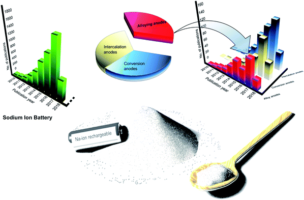 |
| | Fig. 1 Large-format, low-cost SIBs for stationary electrochemical energy storage and research progress in SIB and alloy anodes for SIBs. (Data source: Web of Science, 01-May-2018). | |
The progress and expertise achieved in LIB technology over the past decades could be translated to SIB research to expedite the progress in the field. In fact, suites of oxides,10–18 sulphides19–23 and sulphates,24–26 fluorides,27–30 phosphates31–37 and fluorophosphates38–41 have already been developed as potential cathodes for SIBs. Many of these cathodes display electrochemical performances tantamount to the commercial LIB cathodes. However, progress in SIB anodes seems to be lagging. While graphite, the anode of choice for LIBs is found to be unsuitable for sodium intercalation,42 hard carbon obtained by the pyrolysis of glucose is found to efficiently intercalate sodium at a potential close to 0 V vs. Na.43 Nevertheless, the low volumetric and gravimetric energy densities of hard carbon call forth the development of high capacity anodes for SIBs which is crucial to achieving the target of large-format and inexpensive SIBs.44–49 In this regard, sodium alloying anodes offering high sodiation capacities are expected to lead the way. Among others, tin, antimony and phosphorous offer high sodiation capacities by forming NaxM (M = Sn, Sb, and P) phases at room temperature. At the same time, these alloy anodes suffer from huge volume changes causing pulverization and cracking of the active materials upon sodiation, leading to fast capacity decay. To overcome these challenges, it is essential to develop an understanding of the sodiation mechanism in these alloying anodes. Furthermore, various strategies have been adopted to confront these challenges, including optimizing the structural design of the active material, use of intermetallics and carbon-based matrices to buffer volume changes and the optimization of the electrolyte and binder to stabilize the solid electrolyte interphase (SEI) are a few among others.
It is worth mentioning that several excellent review articles highlighting the progress in SIBs have been reported in the recent past.5,6,8,9,50–58 At the same time, we believe that a review on alloying anodes with a focus on the sodiation mechanism would help researchers to gain insight and accelerate the progress in this field. In this review, the sodiation mechanism of promising alloying anodes for SIBs – tin, antimony and phosphorus (Fig. 2) is presented from recent literature by both computational and experimental insights. The recent progress and novel strategies employed in each of these alloying anodes are described and the progress in bismuth, germanium and silicon-based anodes for SIBs is also reviewed. A few practical approaches that can improve the electrochemical performance of alloying anodes are discussed. Finally, the outlook and challenges to be addressed to deploy alloy anodes in commercial SIBs are also presented in this review.
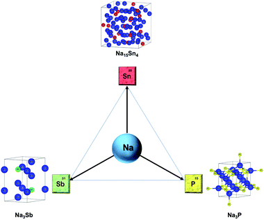 |
| | Fig. 2 Primary alloying anodes of sodium: Sn, P, Sb and the crystal structures of the sodiated phases. | |
2. Tin: the huge volume expansion – a problem?
Tin (Sn50) has been widely investigated as a potential anode for Na-ion batteries owing to its high theoretical capacity of 847 mA h g−1 corresponding to the fully sodiated phase of Na15Sn4. In addition, tin is an earth-abundant and cost-effective as well as environmentally benign metal. For the sodium–tin system, the theoretical voltage profile was calculated (Chevrier et al.59) by means of Density Functional Theory (DFT), making use of the known crystal structures from the Inorganic Crystal Structure Database (ICSD). The proposed sodiation mechanism recognized the formation of intermediates such as NaSn5, NaSn, and Na9Sn4, culminating in the fully sodiated Na15Sn4 phase (Fig. 3a). However, the subsequent experimental results of the Na–Sn system by different research groups were not in agreement with the theoretical calculations. For instance, a study of Sn-polyacrylate electrodes (Komaba et al.60) in aprotic Na cells attributed the observed four plateaus (between 0 V and 0.7 V) (Fig. 3b) to the phases theoretically predicted by Chevrier et al. One year later in 2012, Ellis et al.61 made use of coulometry and suggested a slightly different sodiation mechanism of tin and proposed the formation of an amorphous intermediate phase during the sodiation of tin. Following this in 2017, Stratford et al.62 employed ab initio random structure searching (AIRSS) and high-throughput screening from the ICSD to predict the Na–Sn structures. The local and longer-range structural analysis of the phases formed were then investigated with experimental techniques including operando XRD, pair distribution function (PDF) analysis and solid-state NMR (ssNMR). The proposed mechanism for sodiation of tin is as follows (Fig. 3c):
| Process 1′: Sn, NaSn3 → NaSn2 |
| Process 2: NaSn2 → a-Na1.2Sn |
| Process 2′: a-Na1.2Sn + NaSn2 → a-Na1.2Sn + expanded Na1+xSn2 (solid solution) |
| Process 3: a-Na1.2Sn + expanded Na1+xSn2 → Na4.4Sn2 |
| Process 3′: Na4.4Sn2 → Na4.75Sn2 (solid solution) |
| Process 4: Na4.75Sn2 → Na15Sn4 |
| Process 4′: Na15Sn4 → Na15+xSn4 |
a: amorphous.
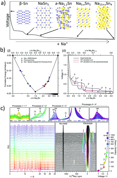 |
| | Fig. 3 (a) Sodiated phased of tin. (b) Formation enthalpy per atom vs. sodium concentration in the Na–Sn compound and electrochemistry data of the sodium–tin cell cycled at a rate of C/20 (corresponding to achieving a capacity of 847 mA h g−1 in 20 h) between 2 and 0.001 V (black line). (c) Operando measurements of tin vs. sodium showing selected PDFs and 23Na-NMR spectra, and the corresponding potential profile obtained during the first discharge. (Reproduced with permission.62 Copyright© 2017, American Chemical Society). | |
According to Stratford and co-workers, during the initial stages of sodiation, the crystalline Sn transforms into a layered structure of approximate stoichiometry NaSn3. Subsequently, NaSn2 is formed, which is structurally similar to NaSn3 and was predicted to be thermodynamically stable. Upon further sodiation, a crystalline to amorphous transformation was observed.
From computational studies and operando PDF measurements, it was found that this amorphous phase is comprised of chains of tin atoms and possesses an approximate composition of Na1.2Sn. It was observed that further reaction with sodium led to the formation of Sn–Sn dumbbell-based structures which interconvert through a solid-solution mechanism. This involved the formation of Na4.4Sn2 followed by the formation of Na5−xSn2 solid-solutions, culminating in Na4.75Sn2. The formation of the fully sodiated Na15Sn4 phase was confirmed by ex situ PDF measurements (Fig. 3c). In addition, the possibility of incorporating excess sodium to form Na15+xSn4 was deliberated as it would not require any Sn–Sn bond breaking and was confirmed by NMR measurements (Fig. 3c). Hence, this study clearly demonstrates the necessity to probe both short and long-range structures along with theoretical modelling to fully fathom the sodiation mechanism of alloying anodes.
Importantly, bare tin undergoes huge volume changes upon sodiation and de-sodiation. A massive 420% volume change is incurred during the phase transformation of Sn to Na15Sn4, leading to pulverization and detachment from the current collector, causing abrupt capacity fade.63 Hence novel strategies to mitigate the ‘ill-effects’ of the volume expansion of Sn need to be adopted to realize the full potential of this high-capacity anode. One such strategy was employed by Tarascon et al.64 to use glyme-based electrolytes in place of the conventionally utilized carbonate-based ones. It was observed that micron-sized tin exhibited enhanced electrochemical performance in 1 M NaPF6 in diethylene glycol dimethyl ether (diglyme, DGME) electrolyte (Fig. 4a and b). A gradual decrease in capacity was noted for the first few cycles which stabilized afterwards to deliver a capacity of 768 mA h g−1 after 100 cycles at a specific current of 250 mA g−1. The use of micron-sized particles also aided the high coulombic efficiency of 99% achieved from the fifth cycle. The superior performance was attributed to the stable SEI formation in glyme-based electrolytes when compared to the carbonate-based systems. The formation of a stable SEI preserved the integrity of the electrode and prevented the separation of the active material from the matrix. Post-cycling examination of the electrodes cycled in glyme-based electrolytes revealed a smoother surface, while a rough surface with cracks was observed in the propylene carbonate (PC) electrolyte counterpart (Fig. 4b inset). The composition of the SEI films was investigated by XPS and for glyme-based electrolytes, they were found to consist of both organic (RCH2ONa) and inorganic (NaF, NaPF6, Na2O, Na2CO3, and phosphates) components. Similar species were found in the SEI films formed in the PC electrolyte as well but in different proportions and were attributed to the higher solubility of sodium carbonates and oxides in PC. The in situ-XRD studies (Fig. 4c) revealed the phase transitions occurring during the alloying reactions. Various NaxSn phases were identified as the alloying reaction of Sn and Na proceeds, culminating in Na15Sn4 upon full sodiation of Sn (Fig. 4d). Furthermore, the viability of a micron-sized tin negative electrode in glyme-based electrolytes was further demonstrated in a full-cell configuration with Na3V2(PO4)3 as the positive electrode (Fig. 4e). The full-cell exhibited 102 mA h g−1 charge capacity and 83 mA h g−1 discharge capacity in the first cycle when cycled at a C/5 rate at an average voltage of 3 V. The full-cell retained 90% of the initial capacity after 50 cycles. An energy density of 200 W h kg−1 (considering the mass of the active materials in the cathode and anode) is achieved in the 50th cycle. When compared with an NVP-carbon full cell, the NVP-tin full cell exhibited 19% higher gravimetric and 61% higher volumetric energy densities (Fig. 4f). Further studies on the long-term stability and the cost of glyme-based electrolyte systems are called for to advance tin-based high-performance anodes for SIBs.
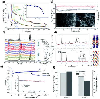 |
| | Fig. 4 (a and b) Performance of the Sn electrode in the diglyme electrolyte. (c and d) In situ-XRD patterns during the first cycle and Rietveld refinement (Na atoms are labelled in orange and Sn atoms are labelled in blue). (e and f) Full cell performance of the Sn anode with hard carbon. (Reproduced with permission.64 Copyright© 2016, John Wiley and Sons). | |
Another significant approach was the deployment of porous tin anodes fabricated by a phase-inversion technique. The porous structure was able to mitigate the ill-effects of the volume expansion as evident from the high reversible capacity of 524 mA h g−1 retained after 500 cycles and a high coulombic efficiency of ∼99%.65 Hence, the use of Sn as the active material in SIBs should consider the huge volume changes occurring during the sodiation process. Table 1 summarizes various strategies adopted to overcome the cycling instability issue in the tin anode including structural modifications, incorporation of the active/inactive buffer matrix, and Sn–M intermetallics among others. By adopting these strategies, the electrode disintegration resulting from the volume expansion can be controlled and the cycling stability can be enhanced.
Table 1 Comparison of performance of tin-based anodes in recent literature
| Sn-based anodes-morphology/structure |
Synthesis method |
Sodiation capacity (second cycle) |
Capacity retention (cycle life) |
Potential Window (V vs. Na) |
| Porous tin65 |
Phase-inversion technique |
659 mA h g−1@423.5 mA g−1 |
∼77% (500 cycles) |
0.001–1 |
| Tin nanoparticles encapsulated in graphene backboned carbonaceous foams66 |
Hydrogen-assisted thermal reduction |
∼600 mA h g−1@400 mA g−1 |
∼84% (500 cycles) |
0.01–2 |
| Sn nanoparticles@nitrogen-doped carbon nanofiber composites67 |
Electrospinning |
∼690 mA h g−1@84.7 mA g−1 |
∼87% (200 cycles) |
0–2.5 |
| Sn coated reduced graphene oxide–graphene composite68 |
Camera flash reduction |
∼690 mA h g−1@423.5 mA g−1 |
∼72% (100 cycles) |
0.01–2 |
| Yolk–shell carbon encapsulated tin69 |
Hydrothermal synthesis |
∼500 mA h g−1@100 mA g−1 |
∼80% (100 cycles) |
0.02–3 |
| Multi-layered 2D Sn nano-dendrites70 |
Electrodeposition |
∼783 mA h g−1@100 mA g−1 |
∼96% (300 cycles) |
0.001–0.65 |
| Sn4P3 nanotops71 |
Solution-based synthesis |
∼600 mA h g−1@50 mA g−1 |
∼83% (80 cycles) |
0.01–2 |
| Sn4P3/reduced graphene oxide hybrids72 |
Solution-based synthesis |
∼900 mA h g−1@100 mA g−1 |
∼77% (100 cycles) |
0.01–3 |
| Sn4P3/graphene nanocomposite73 |
Mechanochemical synthesis |
∼600 mA h g−1@1 A g−1 |
∼99% (1000 cycles) |
0–2 |
![[thin space (1/6-em)]](https://www.rsc.org/images/entities/char_2009.gif) |
|
Intermetallics of Sn
|
| SnTe–carbon composite74 |
Solid state synthesis |
∼541 mA h g−1@50 mA g−1 |
∼99.1% (100 cycles) |
0–2.5 |
| MnSn2 alloy75 |
Ball milling method |
∼400 mA h g−1@18.35 mA g−1 |
∼89.8% (50 cycles) |
0–1.5 |
| FeSn2–graphite composite76 |
Solvothermal and ball milling method |
∼450 mA h g−1@100 mA g−1 |
∼83% (200 cycles) |
0.005–2 |
| SnSe nanoparticles confined in graphene77 |
Ball milling method |
∼410 mA h g−1@1 A g−1 |
∼95% (120 cycles) |
0.01–2 |
| SnSe2 2D anodes78 |
Hydrothermal method |
∼600 mA h g−1@100 mA g−1 |
∼88% (100 cycles) |
0.005–2.5 |
| SnCo/carbon composite79 |
Solution-based synthesis |
∼300 mA h g−1@100 mA g−1 |
∼87% (120 cycles) |
0.1–2 |
3. Antimony: novel strategies to improve the cycling performance
Antimony (Sb51) is one of the most promising alloying anodes for SIBs as it offers a high theoretical sodiation capacity of 660 mA h g−1 corresponding to the fully sodiated Na3Sb phase. Understanding the sodium storage mechanism of antimony can help to devise efficient strategies to improve its electrochemical performance. In the past, various groups have investigated the sodiation mechanism of antimony. Among them, the sodiation of thin films of antimony was investigated by means of 121Sb Mössbauer spectroscopy (Baggetto et al.80). The formation of an amorphous intermediate phase resembling NaSb was suggested, which was followed by the formation of a crystalline Na3Sb phase upon full sodiation. Later, studies by Monconduit et al.81 reported the buffering of the strain by an intermediate amorphous phase leading to the improved sodiation performance of micrometric antimony. It was only recently that Allan et al.82 used coupled PDF analysis and solid-state NMR to further understand the alloying mechanism of antimony in SIBs (Fig. 5). The previously uncharacterized intermediate phases have been identified in the study and the (de-)sodiation mechanism was explained as follows (Fig. 5a and b):
| 1st sodiation: c-Sb → a-Na3−xSb + c-Na3Sb → c-Na3Sb |
| 1st desodiation: c-Na3Sb → a-Na1.7Sb → a-Na1.0Sb → a-Na1.0Sb + c-Sb |
| 2nd sodiation: a-Na1.0Sb + c-Sb → a-Na1.7Sb + c-Sb → a-Na1.7Sb + a-Na3−xSb →a-Na3−xSb → c-Na3Sb |
c: crystalline, a: amorphous.
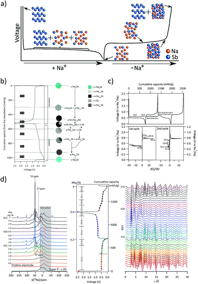 |
| | Fig. 5 (a) Structural changes to antimony during the sodiation/de-sodiation process. (b) PDF and NMR derived mechanisms of (de) sodiation of antimony. (c) (De)sodiation curves and corresponding dQ/dV plots for the 1st and 2nd cycles at a C/20 rate. (d) Ex situ23Na-NMR and PDF spectra of the cycled antimony electrodes. (Reproduced with permission.82 Copyright© 2016, American Chemical Society). | |
Briefly, the sodiation of antimony was observed to proceed through two intermediate amorphous phases Na3−xSb and Na1.7Sb, which alleviated the strain associated with multiple phase transitions. Upon full sodiation, the electrode composition was comprised of amorphous and crystalline antimony networks. These components had different reaction voltages aiding a sequential reaction profile (Fig. 5c) with the inactive component accommodating the strain generated during the sodiation of the active components. Ex situ23 Na NMR and PDF analyses (Fig. 5d) indicated the formation of amorphous Na3−xSb phases during the initial sodiation of Sb. The absence of the NaSb phase during sodiation or desodiation of Sb at room temperature was ascribed to the lack of mobility of Sb within the NaxSb phases. Similarly, the formation of under-sodiated a-Na3−xSb was attributed to the difficulties in nucleating Na3Sb where the breaking of Sb–Sb bonds is required. On the other hand, the good rate performance of antimony was attributed to the high sodium mobility in the crystalline Na3Sb phase aiding facile structural transformations during sodium movement in and out of the structure.
However, antimony undergoes a volume change of ∼293% during the alloying reaction with Na to form Na3Sb.83 This induces pulverisation of the Sb particles and the loss of electrical contact with the conducting matrix. Moreover, the freshly formed Sb surface when exposed to the electrolyte can result in the formation of a new SEI, causing further irreversible capacity losses. One of the approaches employed to improve the cycling stability is to make use of an effective matrix to contain the Sb particles. In this regard, Wu et al.84 investigated the performance of Sb–carbon (Sb–C) nanofibers synthesized through a facile electrospinning technique (Fig. 6a and b). The nanofibers delivered nearly 631 mA h g−1 at a C/15 rate and retained ∼90% of the capacity after 400 cycles (Fig. 6c). The superior performance of the Sb–C nanofibers was attributed to the well-dispersed antimony nanoparticles in the unique nanofiber structure (Fig. 6b) and the conducting and buffering effect of the supporting carbon matrix during Na insertion and extraction.
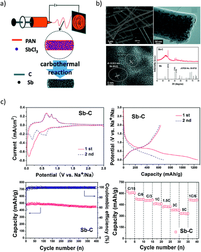 |
| | Fig. 6 Sb–C Nanofibers. (a) Schematic illustration of the synthesis process; (b) SEM, TEM images and XRD pattern of the Sb–C nanofibers. (c) Electrochemical performance of the Sb–C nanofibers. (Reproduced with permission.84 Copyright© 2014, The Royal Society of Chemistry). | |
Recently, Liu et al. proposed a galvanic replacement technique to synthesize hollow Sb–C yolk–shell spheres (Fig. 7a) that delivered superior sodium storage performance.85 The void space in the Sb yolk allowed volume expansion during the sodium storage and the carbon shell facilitated stable SEI formation. The yolk–shell spheres delivered a reversible capacity of 280 mA h g−1 at 1 A g−1 after 200 cycles (Fig. 7b). Similarly, free-standing metallic Sb nanosheets were synthesized from the grey Sb allotrope (Gu et al.86) by means of a liquid-phase exfoliation technique in an isopropyl alcohol–sodium hydroxide solution. The obtained Sb nanosheets were of ∼4 nm thickness with graphene-like foldable features and large aspect ratios (Fig. 7c). Furthermore, hybrid sheets of graphene and Sb nanosheets with tuneable densities were also fabricated and they demonstrated excellent electrochemical performance with a reversible volumetric capacity of 1126 mA h cm−3 (Fig. 7d).
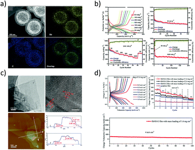 |
| | Fig. 7 (a) Dark-field TEM micrographs and elemental maps of Sb–C yolk–shell particles. (b) Sodium-storage performance of the yolk–shell particles. (Reproduced with permission.85 Copyright© 2017, American Chemical Society). (c) TEM and AFM images of liquid-phase exfoliated Sb nanosheets of thickness 3.0 to 4.3 nm and their sodium-storage performance (d). (Reproduced with permission.86 Copyright© 2017, John Wiley and Sons). | |
Another noteworthy strategy to overcome the capacity decay arising from volume changes to the Sb anode was illustrated by Gao et al.87 by employing a cross-linked chitosan polymer network binder. The Sb particles were immobilized in the cross-linked chitosan network which suppressed the adverse mechanical effects from huge volume expansion and thereby enhanced the electrochemical performance. The electrode exhibited a capacity of ∼555 mA h g−1 at a 1C rate over 100 cycles with 96.5% capacity retention and ∼99% coulombic efficiency. Furthermore, the cross-linked chitosan binder outclassed the conventional CMC and PVDF binders in terms of cycling performance.
While the formation of amorphous phases and fewer phase transitions during the sodiation of Sb enables better performance when compared to Sn, structural modification to Sb and the application of Sb–M intermetallics are other strategies to improve the electrochemical performance of Sb anodes. Table 2 summarizes the novel strategies employed in the recent past by various research groups.
Table 2 Comparison of performance of antimony-based anodes in recent literature
| Sb-based anodes-morphology/structure |
Synthesis method |
Sodiation capacity (second cycle) |
Capacity retention (cycle life) |
Potential window (V vs. Na) |
| Antimony hollow nanospheres85 |
Galvanic replacement reaction |
∼627 mA h g−1@400 mA g−1 |
∼99.6% (50 cycles) |
0.01–2 |
| Cypress leaf-like Sb88 |
Chemical replacement reaction |
∼640 mA h g−1@100 mA g−1 |
∼98% (120 cycles) |
0.01–2 |
| Sb nanoparticles anchored on carbon nanofiber networks89 |
Pyrolysis combined with NaBH4 reduction |
∼542 mA h g−1@100 mA g−1 |
∼96.7% (100 cycles) |
0.01–2 |
| 3-D gradational Sb–NiSb–Ni heterostructures90 |
Pulsed electrodeposition |
650 mA h g−1 @66 mA g−1 |
∼62% (300 cycles) |
0.01–1.5 |
| Spherical nano Sb-carbon composite91 |
Spray pyrolysis |
∼435 mA h g−1@100 mA g−1 |
∼88.5% (500 cycles) |
0.01–2 |
| Sb nanospheres on graphene92 |
Solution-based synthesis |
∼460 mA h g−1@250 mA g−1 |
∼97% (200 cycles) |
0.01–2 |
| Sb/C fibers93 |
Electrospinning |
∼420 mA h g−1@100 mA g−1 |
∼83% (300 cycles) |
0–2 |
| Sb nanodot embedded 2D carbon nanosheets94 |
Solution-based top-down strategy |
∼461 mA h g−1@100 mA g−1 |
∼82% (250 cycles) |
0.005–2 |
![[thin space (1/6-em)]](https://www.rsc.org/images/entities/char_2009.gif) |
|
Intermetallics of Sb
|
| SnSb nanocrystals95 |
One-pot reduction |
∼400 mA h g−1@660 mA g−1 |
∼87% (100 cycles) |
0.02–1.5 |
| Reduced graphene oxide/SnSb nanocomposites96 |
Hydrothermal reaction |
∼450 mA h g−1@100 mA g−1 |
∼87% (80 cycles) |
0.001–2.5 |
| Nanoporous Bi2Sb6 (ref. 97) |
Chemical dealloying process |
∼562 mA h g−1@200 mA g−1 |
∼76% (100 cycles) |
0.01–2 |
| Cu2Sb nanoparticles integrated on Cu foil98 |
Replacement reaction |
∼400 mA h g−1@660 mA g−1 |
∼98% (200 cycles) |
0.05–2 |
| Ni–Sb intermetallic hollow nanospheres99 |
Solvothermal and ball milling method |
∼600 mA h g−1@66 mA g−1 |
∼83% (70 cycles) |
0.01–2 |
| Fe–Sb ribbons100 |
Melt-spinning technique |
∼466 mA h g−1@50 mA g−1 |
∼95% (80 cycles) |
0.005–2 |
| Zn4Sb3 intermetallic nanowires101 |
Self-catalysis using reactive vapor transport |
∼350 mA h g−1@41.4 mA g−1 |
∼86% (200 cycles) |
0.01–2 |
| Zn4Sb3 films102 |
Electrodeposition |
∼400 mA h g−1@97.2 mA g−1 |
∼90% (250 cycles) |
0.1–1.2 |
4. Phosphorous: confronting the poor conductivity and cycling instability
Among others, probably elemental phosphorus (P15) has the highest theoretical sodiation capacity of all known materials (2596 mA h g−1 corresponding to the Na3P sodiated phase).103 This is even higher than the electrochemical capacity of metallic Na (1166 mA h g−1). Pioneering studies on the sodiation/lithiation processes in phosphorous were carried out by Mayo and co-workers104 through a first-principles structure prediction study combined with NMR calculations. The local environment evolution of phosphorous during sodiation/lithiation was predicted by calculating average voltage profiles, energy density of states and NMR chemical shielding of the ground state phases (Fig. 8a–c). A new phase, Na5P4 with C2/m symmetry was predicted to exhibit a layered structure comprised of sodium sheets separated by four-bound in-plane phosphorus chains. The new phase was calculated to be thermodynamically stable and was further confirmed by the phonon dispersion calculations, indicating a possibility to be observed in future experimental studies. The volume change during the formation of various NaxP phases with respect to black phosphorus was also calculated using DFT-PBE lattice parameters (Table 3).
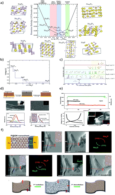 |
| | Fig. 8 (a) Formation enthalpy per atom versus the fractional sodium concentration in the Na–P compound. (b) Calculated average voltages for the Na–P phases. (c) Calculated 31P-NMR chemical shifts for various Na–P phases. (Reproduced with permission.104 Copyright© 2017 American Chemical Society). (d) Amorphous P–graphene anode with a “butter-bread” structure. (e) Galvanostatic cycling performance and potential profiles (f). In situ-HRTEM sodiation and the time dependent TEM images with SAED patterns. (Reproduced with permission.105 Copyright© 2016, American Chemical Society). | |
Table 3 Volume change during the formation of various NaxP phases
|
x in NaxP |
Volume per P atom (Å3) |
Volume change (%) |
| 0 |
19.28 |
— |
| 3/11 |
29.98 |
55.50 |
| 3/7 |
36.25 |
88.04 |
| 1 |
42.33 |
119.58 |
| 5/4 |
49.37 |
156.10 |
| 3 |
94.89 |
392.25 |
When compared to tin and antimony, the phosphorus anode suffers from inherently poor conductivity in addition to its enormous volume changes during (de-)sodiation reactions. To overcome this problem, Zhang et al.105 introduced an innovative flexible paper made of nitrogen-doped graphene and amorphous phosphorus as the anode (Fig. 8d). The restructured anode exhibited excellent structural integrity and demonstrated a remarkable capacity of ∼809 mA h g−1 at a high specific current of 1500 mA g−1 (Fig. 8e). The restructured anode also exhibited a good capacity retention of >85% after 350 cycles at 800 mA g−1. Furthermore, the sodiation process was investigated via in situ HRTEM studies (Fig. 8f). The superior electrochemical performance of the restructured anode was attributed to the relatively smaller volume change of amorphous phosphorus over the crystalline phase, as well as the excellent electrical conductivity and robustness of the N-doped graphene networks which also effectively buffer the volume changes in the electrode.
To further improve the electrochemical performance of phosphorous-based anodes, it is crucial to investigate the formation and the stability of the solid-electrolyte interphase. In this regard, Dahbi et al.106 probed the evolution of the electrode/electrolyte interphase of the black phosphorus negative electrode in Na cells. The formation of the SEI in NaPF6 electrolyte with fluoroethylene carbonate (FEC) and vinylene carbonate (VC) additives was investigated using hard X-ray photoelectron spectroscopy (HAXPES) and time-of-flight secondary ion mass spectroscopy (TOF-SIMS). The SEI layer was found to comprise mainly inorganic species originating from the decomposition of the electrolyte solvent and additives. The accumulation of organic carbonate species was found near the electrode surface and in addition, inorganic salt decomposition species were also observed. The sodiated phase Na3P is found to be highly reactive, causing severe electrolyte decomposition leading to rapid capacity fading. Longer cycling life and better reversibility were achieved for 1 M NaPF6 in EC/DEC electrolyte with the VC additive (Fig. 9). The addition of FEC and VC additives into the electrolyte resulted in the formation of a stable surface layer via decomposition and polymerization of FEC (Fig. 9b) and VC (Fig. 9c) which passivated the electrode and suppressed the electrolyte decomposition. Further studies are called for to investigate the VC additive to realize SIBs with long calendar life.
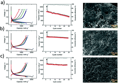 |
| | Fig. 9 Electrochemical properties of black P/polyacrylonitrile electrodes in Na-cells. Potential profiles and reversible capacity of phosphorous electrodes in 1 M NaPF6/EC/DEC/electrolyte: (a) without additive, (b) with fluoroethylene carbonate additive, and (c) with vinylene carbonate additive and corresponding SEM images of cycled electrodes. (Reproduced with permission.106 Copyright© 2016, American Chemical Society). | |
Recently, hollow nanospheres of red phosphorous (HPN) with porous shells and controlled diameters were fabricated by Zhou et al.107 through a solvothermal technique and their performance as LIB and SIB anodes was investigated (Fig. 10a). The HPN anodes demonstrated excellent electrochemical performance as SIB anodes, retaining a high reversible capacity of ∼969 mA h g−1 at 1C (2.6 A g−1) (Fig. 10b). The hollow nanospheres maintained their morphology even after cycling, suggesting the capability of the spheres to accommodate volume-expansion induced strain.
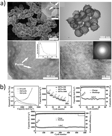 |
| | Fig. 10 (a) SEM and TEM images of the prepared hollow nanospheres (HPNs); (b) cycling stability and rate performance of HPNs vs. sodium. (Reproduced with permission.107 Copyright© 2017, John Wiley and Sons). | |
In addition to the volume expansion issue, the intrinsic low conductivity of pure phosphorus requires a conductive matrix, mainly carbon or metallic-based to improve the electrochemical performance. Moreover, the high reactivity of the sodiated Na3P phase also requires tuning the solid-electrolyte interphase to minimize the subsequent electrolyte decomposition. Various compounds such as carbon-phosphorous composites and metallic phosphides were investigated as negative electrodes for SIBs and are summarized in Table 4.
Table 4 Comparison of performance of phosphorous-based anodes in recent literature
| P-based anodes-morphology/structure |
Synthesis method |
Sodiation capacity (second cycle) |
Capacity retention (cycle life) |
Potential Window (V vs. Na) |
| Integrated carbon/red phosphorus/graphene aerogel 3D architecture108 |
Vapour-redistribution technique |
∼2086 mA h g−1@260 mA g−1 |
∼89.5% (100 cycles) |
0.01–2 |
| Amorphous red phosphorus/carbon composite109 |
High energy ball-milling |
∼1400 mA h g−1@250 mA g−1 |
∼71% (80 cycles) |
0.01–2 |
| Amorphous red phosphorus/carbon composite110 |
High energy ball-milling |
∼1890 mA h g−1@143 mA g−1 |
∼93% (30 cycles) |
0–1.5 |
| Phosphorene–graphene hybrid111 |
Solution-based synthesis |
∼1450 mA h g−1@8 A g−1 |
∼84% (100 cycles) |
0.02–1.5 |
| Red phosphorus nanodots on reduced graphene oxide112 |
Physical vapor deposition |
∼1074.5 mA h g−1@1593.9 mA g−1 |
∼86.6% (100 cycles) |
0.01–1.75 |
| Red P–TiP2–C nanocomposite113 |
High energy mechanical milling |
∼755 mA h g−1@200 mA g−1 |
∼80.4% (100 cycles) |
0–1.5 |
| FeP114 |
Ball milling |
∼465 mA h g−1@50 mA g−1 |
∼69% (60 cycles) |
0–1.5 |
| NiP3 (ref. 115) |
Ball milling and ceramic routes |
∼1000 mA h g−1@159.1 mA g−1 |
∼81% (20 cycles) |
0–2.5 |
| CoP116 |
Ball milling |
∼470 mA h g−1@100 mA g−1 |
∼65.5% (25 cycles) |
0–1.5 |
| SiP2 (ref. 117) |
Ball milling |
∼750 mA h g−1@890 mA g−1 |
∼71% (15 cycles) |
0–1.5 |
5. Progress in bismuth, germanium and silicon based anodes
In addition to tin, antimony and phosphorus, elements such as Bi, Ge and Si are also known to form various NaxM (M = Bi, Ge, Si) phases at ambient temperature. For instance, bismuth forms NaBi and Na3Bi at room temperature and has a theoretical capacity of 385 mA h g−1 corresponding to the fully sodiated Na3Bi phase.118 However, reports on the sodiation mechanism of Bi are quite inconsistent. The in operando XRD studies (Ellis et al.119) on the sputtered Bi anode revealed the sodiation to proceed according to the Na–Bi phase diagram (Fig. 11a and b) with the formation of NaBi and terminating in the fully sodiated Na3Bi phase. On the other hand, Su et al.120 investigated graphene wrapped Bi nanoparticles and concluded that the large interlayer spacing along the c-axis (d (003) = 3.95 Å) facilitates intercalation of Na-ions vs. alloying and supported the claim by the ex situ XRD measurements as well as DFT calculations.
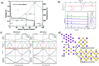 |
| | Fig. 11 (a) Voltage curve of the first sodiation half-cycle of sputtered bismuth overlaid onto the Na–Bi binary phase diagram. (Reproduced with permission.118,119 Copyright© 2014, The Electrochemical Society). (b) Differential profiles and ex situ XRD patterns of the Bi/graphene nanocomposite at different charge and discharge states. (Reproduced with permission.120 Copyright© 2015, Elsevier). (c) Voltage profiles, Na–Bi phase fractions and the relative edge shifts. (d) Illustration of the different structural and electrochemical pathways in the Na–Bi system. (Reproduced with permission.,121 Copyright© 2016, American Chemical Society). | |
Recently, Sottmann and co-workers121 elucidated the influence of the crystallite size of Bi on the sodiation mechanism. It was found that the nano crystallite size alters the Na–Bi system and influences the electrochemical performances, including cycling stability. From in operando synchrotron XRD/XAS studies, it was concluded that nano-sized Bi forms a cubic Na3Bi phase upon sodiation whereas the micro-sized Bi forms a hexagonal Na3Bi phase (Fig. 11c and d). This difference in the reaction pathway is said to impart the difference in the electrochemical performances of nano and micro Bi, with the former exhibiting superior cycling stability over the latter.
According to the Na–Si phase diagram, silicon is reported to form four intermetallic phases with Na: NaSi, NaSi2, Na4Si23, and NaSi94.122 The NaSi phase corresponds to a theoretical capacity of 954 mA h g−1. However, previous studies by Komaba et al.60 and Ellis et al.119 showed that Si is electrochemically inactive at room temperature or even up to 60 °C. It was only recently that Zhao and co-workers123 reported a Si–carbon nanocomposite obtained via ball milling to deliver ∼300 mA h g−1 at a specific current of 100 mA g−1 for 100 cycles in the potential window of 0.01–3 V vs. Na. Similarly, the sodiation behaviour of amorphous silicon prepared through various synthetic routes including chemical delithiation, high-energy ball milling and mechanical fusion methods was investigated by Lim and others.124 The mechanically fused Si–Sn composite exhibited a stable capacity of ∼150 mA h g−1 at 36.25 mA g−1 for over 100 cycles. Lately, the sodiation of the crystalline silicon anode was examined via in operando Raman and XRD analysis by Zhang et al. (Fig. 12).125 The crystalline Si anode was found to undergo an irreversible crystal structure transformation during the first sodiation/desodiation process leading to an irreversible amorphous Si phase. During the subsequent cycles, the amorphous phase was found to reversibly react with sodium. However, pure nano-sized crystalline Si still exhibited poor cycling stability, and this was attributed to the volume changes during sodium insertion/extraction leading to structural degradation and instability. To improve the cycling stability, a bamboo rattle type Si/C film with a well-defined yolk–shell architecture was fabricated via electrospinning and exhibited ultrafast sodium storage with high capacity and cycling stability (Fig. 12a–c). The poor conductivity and inferior structural stability of amorphous silicon were mitigated by the 3D carbon framework which also imparts flexibility and mechanical integrity to the anode, resulting in the excellent electrochemical performance. The potential profiles (Fig. 12d) indicate the typical alloying reaction during the initial (de-)sodiation processes and the capacitive behaviour in the subsequent cycles. Moreover, the operando XRD investigation of micro sized crystalline silicon (Fig. 12e) revealed the absence of structural changes or reversible reactions and suggested the strong dependence of particle size and surface area on the electrochemical performance of crystalline silicon.
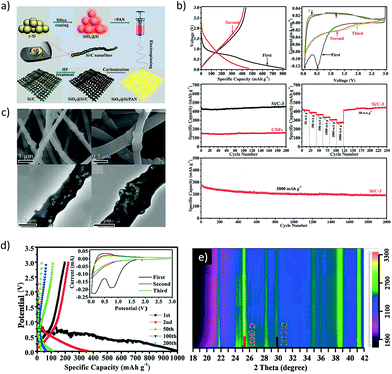 |
| | Fig. 12 (a) Illustration of the Si–C composite design. (b) Electrochemical performance of the Si–C composite as a sodium-ion battery anode. (c) SEM and TEM images of the bamboo-rattle like Si–C architecture. (d) Potential profiles of nano sized Si and (e) Operando XRD plot of micro sized Si vs. sodium. (Reproduced with permission.125 Copyright© 2016, John Wiley and Sons). | |
Germanium has received great attention in recent years as a potential candidate for electrochemical energy storage applications.126 Ge has a theoretical sodiation capacity of 369 mA h g−1 corresponding to the NaGe phase upon full sodiation. The first report on Ge thin germanium thin film anodes for SIBs was by Baggetto et al.127 A reversible capacity of ∼350 mA h g−1 was obtained for thin film electrodes but the capacity was found to fade after 15 cycles due to the volume expansion. The capacity retention was improved considerably by using the FEC additive which facilitated the formation of a thinner SEI. Thin film electrodes also demonstrated excellent rate capability retaining close to 220 mA h g−1 at 170C and 110 mA h g−1 at 340C. It was recently demonstrated by different research groups that the high diffusion barrier for Na ions in crystalline Ge could be considerably lowered by making use of amorphous Ge with high defect density.128–130 Recently, real time in situ transmission electron microscopy (TEM) (Fig. 13a and b) was employed to investigate (de)sodiation processes in Ge nanowires (Lu and co-workers131). It was found that only amorphous Ge nanowires undergo sodiation/desodiation and the crystalline Ge nanowires were inactive. Upon sodiation, the amorphous nanowires exhibited nearly 300% volume expansion corresponding to Na1.6Ge, indicating a higher capacity than NaGe. The desodiation of nanowires led to the formation of pores, which disappear when the nanowires were again sodiated (Fig. 13b). Similarly, Ge nanoparticles encapsulated in hollow carbon boxes were synthesized by Li and co-workers by a carbothermal reaction route (Fig. 13c).132 After 500 cycles at a specific current of 100 mA g−1, the anode displayed a remarkable sodium storage capacity of 346 mA h g−1 (Fig. 13d). The enhanced electrochemical performance is attributed to the internal void space of the carbon boxes which accommodate the volume expansion as well as the interconnectivity of the carbon shell that imparts good electrical conductivity to the electrode. Further studies are necessary to elucidate the sodiation mechanism in amorphous Ge particles and the cycling performance to facilitate their application in practical SIBs.
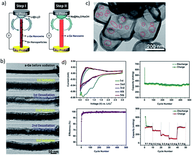 |
| | Fig. 13 (a) Illustration of the in situ TEM procedure on the Ge nanowire. (b) Structural evolution of the Ge nanowire during (de) sodiation cycles. (Reproduced with permission.131 Copyright© 2016, American Chemical Society). (c) Hollow carbon boxes encapsulating Ge and the electrochemical performance is presented in (d). (Reproduced with permission.132 Copyright© 2017 John Wiley and Sons.). | |
6. Mitigating the challenges of alloying anodes
One of the primary challenges hindering the deployment of alloying anodes in practical sodium-ion batteries is their cycling instability induced by the huge volume expansion. In the previous sections we have expounded the sodiation mechanisms in alloying anodes, the knowledge of which can help devise efficient sodiation pathways thereby improving the electrochemical performance. The various strategies adopted to improve the performance of alloying anodes can be summarized as follows:
6.1 Engineering the active materials
Structural and morphological modification of the active material is one of the widely adopted strategies to alleviate the problem of particle pulverization during (de)sodiation reactions. Making use of porous/hollow active materials was found to improve the particle integrity during the cycling process and enhance the calendar life. The approach seems promising in terms of the electrochemical performance while the scale-up of the synthesis techniques is a concern to be addressed. Another approach was to embed the active material in a carbon matrix including the in situ encapsulation during the synthesis or post-processing via carbonization or ball-milling. The carbon matrix was found to improve the conductivity as well as buffer the volume changes during electrochemical cycling. Again, the low tap-density of carbon should be considered, and the carbon content should be minimized to avoid any penalty in the volumetric energy density. Recently, nano-engineering of active materials including the utilization of 2D nanosheets of alloying anodes (antimonene and phosphorene) has gained significant attention. The 2D nanosheets were found to effectively buffer the volume changes and could be a promising approach if cost-effective and scalable synthesis processes are devised.
6.2 Intermetallics to improve the cycling stability
Recently, intermetallics of tin, antimony and phosphorous (M–Sn/Sb/P) have gained interest because of their superior electrochemical performance when compared to the bare alloying elements. Most of these intermetallics can be synthesized by scalable, industrially viable techniques including ball-milling, solid state synthesis and melt-spinning to name a few. The accompanying element ‘M’ in the intermetallic could be active or inactive towards sodium storage. For instance, in SnSb, both Sn and Sb are active while in FeSn2 only Sn is electrochemically active. The component ‘M’, whether active or inactive, still plays a vital role in enhancing the performance. In most cases, during the first sodiation process of the intermetallic anode, the component ‘M’ is extracted out and forms a matrix for the sodiated active component. The enhanced electrochemical performance of the intermetallic anode is mainly due to the buffering of the stress by this matrix. Then again, the choice of the inactive component should be carefully considered to minimise the additional weight penalty.
6.3 Tuning the solid-electrolyte interphase layer
It is the stable SEI layer that is formed on the graphite anode in lithium-ion batteries that prevents the exfoliation of graphite and has made it a commercial success. The SEI layer plays an important role in determining the cycling life of alloying anodes. A crucial role in tuning the SEI layer is played by the choice of the electrolyte. Most of the studies on sodium-ion batteries report the use of NaClO4/NaPF6 salts in propylene carbonate and ethylene carbonate-based solvents as the electrolytes. Recent studies have shown the advantages of using electrolyte additives such as fluoroethylene carbonate and vinylene carbonate to improve the cycling stability of alloying anodes. These additives are found to improve the quality of the SEI layer formed and thereby facilitate enhanced electrochemical performance. However, more studies on full-cell configurations as well as the optimisation of electrolyte additives in terms of performance and cost are necessary to enable practical applications.
6.4 Optimal choice of the binder
Another strategy adopted to curb the ill-effects of huge volume expansion is the optimal choice of the binder during the electrode fabrication process. Carboxymethyl cellulose and cross-linked chitosan-based binders have been reported to provide good mechanical stability during the electrochemical (de)sodiation processes and hence improve the cycling stability when compared to polyvinylidene fluoride (PVDF). Additionally, these cellulose-based binders are water-soluble and can thus eliminate toxic solvents such as n-methyl-pyrrolidone used for PVDF. At times, it is necessary to apply a multi-pronged approach of the above discussed strategies to achieve good electrochemical performance for the alloying anodes. The optimal choice of these strategies can facilitate the implementation of alloying anodes for practical applications.
7. Summary and outlook
To summarize, the development of high capacity anodes is crucial to achieve the commercialization of sodium-ion batteries (SIBs) and thereby aid the cost-effective deployment of renewable energy resources. In this regard, research on alloy anodes offering the highest sodiation capacities is inevitable. Tin, antimony and phosphorous can alloy with sodium to form Na15Sn4, Na3Sb and Na3P phases respectively. These alloying reactions can occur at room temperature and hence piqued the interest of the energy storage community. Furthermore, these reactions are reversible and can aid in the deployment of batteries with high energy densities. We have discussed the recent progress in the field of alloying anodes with special emphasis on the sodiation mechanism of these potential candidates that possibly will be commercialized as this knowledge is crucial to deploy various strategies to tackle the challenges faced by alloying anodes.
These interesting Na alloying materials pose certain problems including high volume-expansion during the formation of sodiated phases leading to pulverization of particles and the consequent capacity fade. Hence it is crucial to understand the sodiation mechanism of these remarkable alloying anodes and devise strategies to mitigate the challenges. We have highlighted various approaches adopted to overcome the fundamental issue of cycling instability of alloying anodes such as the structural and morphological design of active materials, use of active/inactive matrices including intermetallics and carbon-based materials to buffer volume changes during cycling and optimizing the electrolyte and binders.
We would also like to stress the fact that the studies of alloy anodes in a full-cell configuration are limited and are highly necessary to facilitate the progress of commercialization of SIBs. Furthermore, the issue of low initial coulombic efficiency of alloy anodes needs to be addressed and strategies to mitigate the same should be implemented to develop SIBs for practical applications. One of the strategies could possibly be the pre-sodiation/pre-treatment of electrodes which would reduce the penalty on the cathode. While most studies on SIBs are carried out in coin cells, the deployment of SIBs in large format cells calls for additional investigations in pouch/prismatic/cylindrical cells to analyse the issues with scale-up from the laboratory to industry. In addition, the thermal and safety aspects of SIBs have not received significant attention and need to be probed to ensure the operational safety of SIBs.
Conflicts of interest
There are no conflicts to declare.
Abbreviations
| NMR | Nuclear magnetic resonance |
| TEM | Transmission electron microscopy |
| XRD | X-ray diffraction |
| XAS | X-ray absorption spectroscopy |
| SAED | Selected area electron diffraction |
| AFM | Atomic force microscopy |
| NVP | Sodium vanadium phosphate (Na3V2(PO4)3) |
| CMC | Carboxymethyl cellulose |
| PVDF | Polyvinylidene fluoride |
| EC/DEC | Ethylene carbonate/diethylene carbonate |
| FEC | Fluoroethylene carbonate |
Acknowledgements
This work was financially supported by the National Research Foundation of Singapore (NRF) Investigatorship award number. NRFI2017-08/NRF2016NRF-NRFI001-22. S. S. and C. T. L. acknowledge support from the National Research Foundation, Prime Minister's Office, Singapore under medium-sized centre program and NUS-BIGHEART.
Notes and references
-
G. M. Insights, Lithium Ion Battery Market to hit $53bn by 2024: Global Market Insights Inc., https://globenewswire.com/news-release/2017/02/08/915005/0/en/Lithium-Ion-Battery-Market-to-hit-53bn-by-2024-Global-Market-Insights-Inc.html, (accessed 01-05-2018, 2018) Search PubMed.
- F. Risacher and B. Fritz, Aquat. Geochem., 2009, 15, 123–157 CrossRef CAS.
- A. Yaksic and J. E. Tilton, Resour. Policy, 2009, 34, 185–194 CrossRef.
-
S. Fletcher, Bottled lightning: superbatteries, electric cars, and the new lithium economy, Hill and Wang, 2011 Search PubMed.
- M. D. Slater, D. Kim, E. Lee and C. S. Johnson, Adv. Funct. Mater., 2013, 23, 947–958 CrossRef CAS.
- D. Kundu, E. Talaie, V. Duffort and L. F. Nazar, Angew. Chem., Int. Ed., 2015, 54, 3431–3448 CrossRef CAS PubMed.
- D. Larcher and J. M. Tarascon, Nat. Chem., 2015, 7, 19–29 CrossRef CAS PubMed.
- N. Yabuuchi, K. Kubota, M. Dahbi and S. Komaba, Chem. Rev., 2014, 114, 11636–11682 CrossRef CAS PubMed.
- K. Kubota and S. Komaba, J. Electrochem. Soc., 2015, 162, A2538–A2550 CrossRef CAS.
- M. Blangero, D. Carlier, M. Pollet, J. Darriet, C. Delmas and J.-P. Doumerc, Phys. Rev. B: Condens. Matter Mater. Phys., 2008, 77, 184116 CrossRef.
- D. Buchholz, L. G. Chagas, M. Winter and S. Passerini, Electrochim. Acta, 2013, 110, 208–213 CrossRef CAS.
- A. Caballero, L. Hernan, J. Morales, L. Sanchez, J. Santos Pena and M. A. G. Aranda, J. Mater. Chem., 2002, 12, 1142–1147 RSC.
- M. Guignard, C. Didier, J. Darriet, P. Bordet, E. Elkaïm and C. Delmas, Nat. Mater., 2013, 12, 74–80 CrossRef CAS PubMed.
- S. Komaba, T. Nakayama, A. Ogata, T. Shimizu, C. Takei, S. Takada, A. Hokura and I. Nakai, ECS Trans., 2009, 16, 43–55 CAS.
- S. Komaba, C. Takei, T. Nakayama, A. Ogata and N. Yabuuchi, Electrochem. Commun., 2010, 12, 355–358 CrossRef CAS.
- X. Ma, H. Chen and G. Ceder, J. Electrochem. Soc., 2011, 158, A1307–A1312 CrossRef CAS.
- D. Yuan, X. Hu, J. Qian, F. Pei, F. Wu, R. Mao, X. Ai, H. Yang and Y. Cao, Electrochim. Acta, 2014, 116, 300–305 CrossRef CAS.
- J. Zhao, L. Zhao, N. Dimov, S. Okada and T. Nishida, J. Electrochem. Soc., 2013, 160, A3077–A3081 CrossRef CAS.
- J. Park, J.-S. Kim, J.-W. Park, T.-H. Nam, K.-W. Kim, J.-H. Ahn, G. Wang and H.-J. Ahn, Electrochim. Acta, 2013, 92, 427–432 CrossRef CAS.
- J.-S. Kim, D.-Y. Kim, G.-B. Cho, T.-H. Nam, K.-W. Kim, H.-S. Ryu, J.-H. Ahn and H.-J. Ahn, J. Power Sources, 2009, 189, 864–868 CrossRef CAS.
- J.-S. Kim, H.-J. Ahn, H.-S. Ryu, D.-J. Kim, G.-B. Cho, K.-W. Kim, T.-H. Nam and J. H. Ahn, J. Power Sources, 2008, 178, 852–856 CrossRef CAS.
- K. M. Abraham, Solid State Ionics, 1982, 7, 199–212 CrossRef CAS.
- M. S. Whittingham, Prog. Solid State Chem., 1978, 12, 41–99 CrossRef CAS.
- D. Dwibedi, C. D. Ling, R. B. Araujo, S. Chakraborty, S. Duraisamy, N. Munichandraiah, R. Ahuja and P. Barpanda, ACS Appl. Mater. Interfaces, 2016, 8, 6982–6991 CrossRef CAS PubMed.
- P. Barpanda, Chem. Mater., 2016, 28, 1006–1011 CrossRef CAS.
- P. Barpanda, G. Oyama, S. Nishimura, S. C. Chung and A. Yamada, Nat. Commun., 2014, 5, 8 Search PubMed.
- I. D. Gocheva, M. Nishijima, T. Doi, S. Okada, J.-i. Yamaki and T. Nishida, J. Power Sources, 2009, 187, 247–252 CrossRef CAS.
- Y. Yamada, T. Doi, I. Tanaka, S. Okada and J.-i. Yamaki, J. Power Sources, 2011, 196, 4837–4841 CrossRef CAS.
- A. Kitajou, H. Komatsu, K. Chihara, I. D. Gocheva, S. Okada and J.-i. Yamaki, J. Power Sources, 2012, 198, 389–392 CrossRef CAS.
- N. Dimov, A. Nishimura, K. Chihara, A. Kitajou, I. D. Gocheva and S. Okada, Electrochim. Acta, 2013, 110, 214–220 CrossRef CAS.
- F. Erragh, A. Boukhari, B. Elouadi and E. M. Holt, J. Crystallogr. Spectrosc. Res., 1991, 21, 321–326 CrossRef CAS.
- P. Moreau, D. Guyomard, J. Gaubicher and F. Boucher, Chem. Mater., 2010, 22, 4126–4128 CrossRef CAS.
- K. T. Lee, T. N. Ramesh, F. Nan, G. Botton and L. F. Nazar, Chem. Mater., 2011, 23, 3593–3600 CrossRef CAS.
- K. Zaghib, J. Trottier, P. Hovington, F. Brochu, A. Guerfi, A. Mauger and C. M. Julien, J. Power Sources, 2011, 196, 9612–9617 CrossRef CAS.
- P. Barpanda, T. Ye, S.-i. Nishimura, S.-C. Chung, Y. Yamada, M. Okubo, H. Zhou and A. Yamada, Electrochem. Commun., 2012, 24, 116–119 CrossRef CAS.
- T. Honma, T. Togashi, N. Ito and T. Komatsu, J. Ceram. Soc. Jpn., 2012, 120, 344–346 CrossRef.
- A. Sun, F. R. Beck, D. Haynes, J. A. Poston, S. R. Narayanan, P. N. Kumta and A. Manivannan, Mater. Sci. Eng., B, 2012, 177, 1729–1733 CrossRef CAS.
- R. K. B. Gover, A. Bryan, P. Burns and J. Barker, Solid State Ionics, 2006, 177, 1495–1500 CrossRef CAS.
- Y. Kawabe, N. Yabuuchi, M. Kajiyama, N. Fukuhara, T. Inamasu, R. Okuyama, I. Nakai and S. Komaba, Electrochem. Commun., 2011, 13, 1225–1228 CrossRef CAS.
- Y.-U. Park, D.-H. Seo, H.-S. Kwon, B. Kim, J. Kim, H. Kim, I. Kim, H.-I. Yoo and K. Kang, J. Am. Chem. Soc., 2013, 135, 13870–13878 CrossRef CAS PubMed.
- Y. Lu, S. Zhang, Y. Li, L. Xue, G. Xu and X. Zhang, J. Power Sources, 2014, 247, 770–777 CrossRef CAS.
- M. M. Doeff, Y. Ma, S. J. Visco and L. C. De Jonghe, J. Electrochem. Soc., 1993, 140, L169–L170 CrossRef CAS.
- D. A. Stevens and J. R. Dahn, J. Electrochem. Soc., 2000, 147, 1271–1273 CrossRef CAS.
- Y. Kim, K. H. Ha, S. M. Oh and K. T. Lee, Chem.–Eur. J., 2014, 20, 11980–11992 CrossRef CAS PubMed.
- M. Mortazavi, Q. Ye, N. Birbilis and N. V. Medhekar, J. Power Sources, 2015, 285, 29–36 CrossRef CAS.
- M.-S. Balogun, Y. Luo, W. Qiu, P. Liu and Y. Tong, Carbon, 2016, 98, 162–178 CrossRef CAS.
- H. Hou, C. E. Banks, M. Jing, Y. Zhang and X. Ji, Adv. Mater., 2015, 27, 7861–7866 CrossRef CAS PubMed.
- Y. Zhang, C. W. Foster, C. E. Banks, L. Shao, H. Hou, G. Zou, J. Chen, Z. Huang and X. Ji, Adv. Mater., 2016, 28, 9391–9399 CrossRef CAS PubMed.
- H. Hou, L. Shao, Y. Zhang, G. Zou, J. Chen and X. Ji, Adv. Sci., 2016, 4, 1600243 CrossRef PubMed.
- M. Sawicki and L. L. Shaw, RSC Adv., 2015, 5, 53129–53154 RSC.
- M. H. Han, E. Gonzalo, G. Singh and T. Rojo, Energy Environ. Sci., 2015, 8, 81–102 RSC.
- S.-W. Kim, D.-H. Seo, X. Ma, G. Ceder and K. Kang, Adv. Energy Mater., 2012, 2, 710–721 CrossRef CAS.
- V. Palomares, P. Serras, I. Villaluenga, K. B. Hueso, J. Carretero-González and T. Rojo, Energy Environ. Sci., 2012, 5, 5884 RSC.
- W. Luo, F. Shen, C. Bommier, H. Zhu, X. Ji and L. Hu, Acc. Chem. Res., 2016, 49, 231–240 CrossRef CAS PubMed.
- C. Bommier and X. Ji, Isr. J. Chem., 2015, 55, 486–507 CrossRef CAS.
- H. Pan, Y.-S. Hu and L. Chen, Energy Environ. Sci., 2013, 6, 2338 RSC.
- B. L. Ellis and L. F. Nazar, Curr. Opin. Solid State Mater. Sci., 2012, 16, 168–177 CrossRef CAS.
- V. Palomares, M. Casas-Cabanas, E. Castillo-Martínez, M. H. Han and T. Rojo, Energy Environ. Sci., 2013, 6, 2312 RSC.
- V. L. Chevrier and G. Ceder, J. Electrochem. Soc., 2011, 158, A1011 CrossRef CAS.
- S. Komaba, Y. Matsuura, T. Ishikawa, N. Yabuuchi, W. Murata and S. Kuze, Electrochem. Commun., 2012, 21, 65–68 CrossRef CAS.
- L. D. Ellis, T. D. Hatchard and M. N. Obrovac, J. Electrochem. Soc., 2012, 159, A1801–A1805 CrossRef CAS.
- J. M. Stratford, M. Mayo, P. K. Allan, O. Pecher, O. J. Borkiewicz, K. M. Wiaderek, K. W. Chapman, C. J. Pickard, A. J. Morris and C. P. Grey, J. Am. Chem. Soc., 2017, 139, 7273–7286 CrossRef CAS PubMed.
- J. W. Wang, X. H. Liu, S. X. Mao and J. Y. Huang, Nano Lett., 2012, 12, 5897–5902 CrossRef CAS PubMed.
- B. A. Zhang, G. Rousse, D. Foix, R. Dugas, D. A. D. Corte and J. M. Tarascon, Adv. Mater., 2016, 28, 9824–9830 CrossRef CAS PubMed.
- C. Kim, K. Y. Lee, I. Kim, J. Park, G. Cho, K. W. Kim, J. H. Ahn and H. J. Ahn, J. Power Sources, 2016, 317, 153–158 CrossRef CAS.
- B. Luo, T. F. Qiu, D. L. Ye, L. Z. Wang and L. J. Zhi, Nano Energy, 2016, 22, 232–240 CrossRef CAS.
- M. Sha, H. Zhang, Y. T. Nie, K. Q. Nie, X. X. Lv, N. Sun, X. K. Xie, Y. Y. Ma and X. H. Sun, J. Mater. Chem. A, 2017, 5, 6277–6283 RSC.
- Y. Jeon, X. G. Han, K. Fu, J. Q. Dai, J. H. Kim, L. B. Hu, T. Song and U. Paik, J. Mater. Chem. A, 2016, 4, 18306–18313 RSC.
- S. T. Li, Z. M. Wang, J. Liu, L. Y. Yang, Y. Guo, L. Z. Cheng, M. Lei and W. J. Wang, ACS Appl. Mater. Interfaces, 2016, 8, 19438–19445 CrossRef CAS PubMed.
- T.-H. Kim, K.-S. Hong, D. Sohn, M. Kim, D.-H. Nam, E. Cho and H. Kwon, J. Mater. Chem. A, 2017, 5, 20304–20315 RSC.
- D. N. Lan, W. H. Wang, L. Shi, Y. Huang, L. B. Hu and Q. Li, J. Mater. Chem. A, 2017, 5, 5791–5796 RSC.
- Q. Li, Z. Q. Li, Z. W. Zhang, C. X. Li, J. Y. Ma, C. X. Wang, X. L. Ge, S. H. Dong and L. W. Yin, Adv. Energy Mater., 2016, 6, 10 Search PubMed.
- Y. Xu, B. Peng and M. Mulder Fokko, Adv. Energy Mater., 2017, 8, 1701847 CrossRef.
- A.-R. Park and C.-M. Park, ACS Nano, 2017, 11, 6074–6084 CrossRef CAS PubMed.
- L. O. Vogt and C. Villevieille, J. Mater. Chem. A, 2016, 4, 19116–19122 RSC.
- E. Edison, W. C. Ling, V. Aravindan and S. Madhavi, ChemElectroChem, 2017, 4, 1932–1936 CrossRef CAS.
- X. Yang, R. Zhang, N. Chen, X. Meng, P. Yang, C. Wang, Y. Zhang, Y. Wei, G. Chen and F. Du, Chem.–Eur. J., 2016, 22, 1445–1451 CrossRef CAS PubMed.
- F. Zhang, C. Xia, J. Zhu, B. Ahmed, H. Liang, D. B. Velusamy, U. Schwingenschlögl and H. N. Alshareef, Adv. Energy Mater., 2016, 6, 1601188 CrossRef.
- B. Huang, J. Yang, Y. Li, S. Xiao and Q. Chen, Mater. Lett., 2018, 210, 321–324 CrossRef CAS.
- L. Baggetto, H. Y. Hah, J. C. Jumas, C. E. Johnson, J. A. Johnson, J. K. Keum, C. A. Bridges and G. M. Veith, J. Power Sources, 2014, 267, 329–336 CrossRef CAS.
- A. Darwiche, C. Marino, M. T. Sougrati, B. Fraisse, L. Stievano and L. Monconduit, J. Am. Chem. Soc., 2013, 135, 10179 CrossRef CAS.
- P. K. Allan, J. M. Griffin, A. Darwiche, O. J. Borkiewicz, K. M. Wiaderek, K. W. Chapman, A. J. Morris, P. J. Chupas, L. Monconduit and C. P. Grey, J. Am. Chem. Soc., 2016, 138, 2352–2365 CrossRef CAS PubMed.
- L. Baggetto, P. Ganesh, C.-N. Sun, R. A. Meisner, T. A. Zawodzinski and G. M. Veith, J. Mater. Chem. A, 2013, 1, 7985–7994 RSC.
- L. Wu, X. Hu, J. Qian, F. Pei, F. Wu, R. Mao, X. Ai, H. Yang and Y. Cao, Energy Environ. Sci., 2014, 7, 323–328 RSC.
- J. Liu, L. Yu, C. Wu, Y. Wen, K. Yin, F.-K. Chiang, R. Hu, J. Liu, L. Sun, L. Gu, J. Maier, Y. Yu and M. Zhu, Nano Lett., 2017, 17, 2034–2042 CrossRef CAS PubMed.
- J. Gu, Z. Du, C. Zhang, J. Ma, B. Li and S. Yang, Adv. Energy Mater., 2017, 7, 1700447 CrossRef.
- H. C. Gao, W. D. Zhou, J. H. Jang and J. B. Goodenough, Adv. Energy Mater., 2016, 6, 7 Search PubMed.
- H. S. Hou, M. J. Jing, Y. Zhang, J. Chen, Z. D. Huang and X. B. Ji, J. Mater. Chem. A, 2015, 3, 17549–17552 RSC.
- H. S. Hou, M. J. Jing, Y. C. Yang, Y. Zhang, W. X. Song, X. M. Yang, J. Chen, Q. Y. Chen and X. B. Ji, J. Power Sources, 2015, 284, 227–235 CrossRef CAS.
- C. W. Lee, J. C. Kim, S. Park, H. J. Song and D. W. Kim, Nano Energy, 2015, 15, 479–489 CrossRef CAS.
- N. Zhang, Y. C. Liu, Y. Y. Lu, X. P. Han, F. Y. Cheng and J. Chen, Nano Res., 2015, 8, 3384–3393 CrossRef CAS.
- F. Wan, J. Z. Guo, X. H. Zhang, J. P. Zhang, H. Z. Sun, Q. Y. Yan, D. X. Han, L. Niu and X. L. Wu, ACS Appl. Mater. Interfaces, 2016, 8, 7790–7799 CrossRef CAS PubMed.
- Y. J. Zhu, X. G. Han, Y. H. Xu, Y. H. Liu, S. Y. Zheng, K. Xu, L. B. Hu and C. S. Wang, ACS Nano, 2013, 7, 6378–6386 CrossRef CAS PubMed.
- C. Wu, L. Shen, S. Chen, Y. Jiang, P. Kopold, P. A. van Aken, J. Maier and Y. Yu, Energy Storage Materials, 2018, 10, 122–129 CrossRef.
- M. He, M. Walter, K. V. Kravchyk, R. Erni, R. Widmer and M. V. Kovalenko, Nanoscale, 2015, 7, 455–459 RSC.
- L. Ji, W. Zhou, V. Chabot, A. Yu and X. Xiao, ACS Appl. Mater. Interfaces, 2015, 7, 24895–24901 CrossRef CAS PubMed.
- H. Gao, J. Niu, C. Zhang, Z. Peng and Z. Zhang, ACS Nano, 2018, 12, 3568–3577 CrossRef CAS PubMed.
- L. B. Wang, C. C. Wang, N. Zhang, F. J. Li, F. Y. Cheng and J. Chen, ACS Energy Lett., 2017, 2, 256–262 CrossRef CAS.
- J. Liu, Z. Z. Yang, J. Q. Wang, L. Gu, J. Maier and Y. Yu, Nano Energy, 2015, 16, 389–398 CrossRef CAS.
- E. Edison, S. Sreejith and S. Madhavi, ACS Appl. Mater. Interfaces, 2017, 9, 39399–39406 CrossRef CAS PubMed.
- A. M. Nie, L. Y. Gan, Y. C. Cheng, X. Y. Tao, Y. F. Yuan, S. Sharifi-Asl, K. He, H. Asayesh-Ardakani, V. Vasiraju, J. Lu, F. Mashayek, R. Klie, S. Vaddiraju, U. Schwingenschlogl and R. Shahbazian-Yassar, Adv. Funct. Mater., 2016, 26, 543–552 CrossRef CAS.
- E. D. Jackson, S. Green and A. L. Prieto, ACS Appl. Mater. Interfaces, 2015, 7, 7447–7450 CrossRef CAS PubMed.
- K. P. S. S. Hembram, H. Jung, B. C. Yeo, S. J. Pai, S. Kim, K.-R. Lee and S. S. Han, J. Phys. Chem. C, 2015, 119, 15041–15046 CrossRef CAS.
- M. Mayo, K. J. Griffith, C. J. Pickard and A. J. Morris, Chem. Mater., 2016, 28, 2011–2021 CrossRef CAS.
- C. Zhang, X. Wang, Q. Liang, X. Liu, Q. Weng, J. Liu, Y. Yang, Z. Dai, K. Ding, Y. Bando, J. Tang and D. Golberg, Nano Lett., 2016, 16, 2054–2060 CrossRef CAS PubMed.
- M. Dahbi, N. Yabuuchi, M. Fukunishi, K. Kubota, K. Chihara, K. Tokiwa, X.-f. Yu, H. Ushiyama, K. Yamashita, J.-Y. Son, Y.-T. Cui, H. Oji and S. Komaba, Chem. Mater., 2016, 28, 1625–1635 CrossRef CAS.
- J. Zhou, X. Liu, W. Cai, Y. Zhu, J. Liang, K. Zhang, Y. Lan, Z. Jiang, G. Wang and Y. Qian, Adv. Mater., 2017, 29, 1700214 CrossRef PubMed.
- H. Gao, T. Zhou, Y. Zheng, Y. Liu, J. Chen, H. Liu and Z. Guo, Adv. Energy Mater., 2016, 6, 1601037 CrossRef.
- J. Qian, X. Wu, Y. Cao, X. Ai and H. Yang, Angew. Chem., Int. Ed., 2013, 52, 4633–4636 CrossRef CAS PubMed.
- Y. Kim, Y. Park, A. Choi, N.-S. Choi, J. Kim, J. Lee, J. H. Ryu, S. M. Oh and K. T. Lee, Adv. Mater., 2013, 25, 3045–3049 CrossRef CAS PubMed.
- J. Sun, H.-W. Lee, M. Pasta, H. Yuan, G. Zheng, Y. Sun, Y. Li and Y. Cui, Nat. Nanotechnol., 2015, 10, 980–985 CrossRef CAS PubMed.
- Y. Liu, A. Zhang, C. Shen, Q. Liu, X. Cao, Y. Ma, L. Chen, C. Lau, T.-C. Chen, F. Wei and C. Zhou, ACS Nano, 2017, 11, 5530–5537 CrossRef CAS PubMed.
- S.-O. Kim and A. Manthiram, Chem. Mater., 2016, 28, 5935–5942 CrossRef CAS.
- W.-J. Li, S.-L. Chou, J.-Z. Wang, H.-K. Liu and S.-X. Dou, Chem. Commun., 2015, 51, 3682–3685 RSC.
- J. Fullenwarth, A. Darwiche, A. Soares, B. Donnadieu and L. Monconduit, J. Mater. Chem. A, 2014, 2, 2050–2059 RSC.
- W.-J. Li, Q.-R. Yang, S.-L. Chou, J.-Z. Wang and H.-K. Liu, J. Power Sources, 2015, 294, 627–632 CrossRef CAS.
- D. Duveau, S. S. Israel, J. Fullenwarth, F. Cunin and L. Monconduit, J. Mater. Chem. A, 2016, 4, 3228–3232 RSC.
-
H. Okamoto, L. Kacprzak and P. Subramanian, Binary Alloy Phase Diagrams, ASM International, 1996 Search PubMed.
- L. D. Ellis, B. N. Wilkes, T. D. Hatchard and M. N. Obrovac, J. Electrochem. Soc., 2014, 161, A416–A421 CrossRef CAS.
- D. Su, S. Dou and G. Wang, Nano Energy, 2015, 12, 88–95 CrossRef CAS.
- J. Sottmann, M. Herrmann, P. Vajeeston, Y. Hu, A. Ruud, C. Drathen, H. Emerich, H. Fjellvåg and D. S. Wragg, Chem. Mater., 2016, 28, 2750–2756 CrossRef CAS.
- J. Songster and A. D. Pelton, J. Phase Equilib., 1992, 13, 67–69 CrossRef.
- Q. Zhao, Y. Huang and X. Hu, Electrochem. Commun., 2016, 70, 8–12 CrossRef CAS.
- C.-H. Lim, T.-Y. Huang, P.-S. Shao, J.-H. Chien, Y.-T. Weng, H.-F. Huang, B. J. Hwang and N.-L. Wu, Electrochim. Acta, 2016, 211, 265–272 CrossRef CAS.
- L. Zhang, X. Hu, C. Chen, H. Guo, X. Liu, G. Xu, H. Zhong, S. Cheng, P. Wu, J. Meng, Y. Huang, S. Dou and H. Liu, Adv. Mater., 2017, 29, 1604708 CrossRef PubMed.
- X. Xiao, X. Li, S. Zheng, J. Shao, H. Xue and H. Pang, Adv. Mater. Interfaces, 2017, 4, 1600798 CrossRef.
- L. Baggetto, J. K. Keum, J. F. Browning and G. M. Veith, Electrochem. Commun., 2013, 34, 41–44 CrossRef CAS.
- B. Farbod, K. Cui, W. P. Kalisvaart, M. Kupsta, B. Zahiri, A. Kohandehghan, E. M. Lotfabad, Z. Li, E. J. Luber and D. Mitlin, ACS Nano, 2014, 8, 4415–4429 CrossRef CAS PubMed.
- P. R. Abel, Y.-M. Lin, T. de Souza, C.-Y. Chou, A. Gupta, J. B. Goodenough, G. S. Hwang, A. Heller and C. B. Mullins, J. Phys. Chem. C, 2013, 117, 18885–18890 CrossRef CAS.
- A. Kohandehghan, K. Cui, M. Kupsta, J. Ding, E. Memarzadeh Lotfabad, W. P. Kalisvaart and D. Mitlin, Nano Lett., 2014, 14, 5873–5882 CrossRef CAS PubMed.
- X. Lu, E. R. Adkins, Y. He, L. Zhong, L. Luo, S. X. Mao, C.-M. Wang and B. A. Korgel, Chem. Mater., 2016, 28, 1236–1242 CrossRef CAS.
- Q. Li, Z. Zhang, S. Dong, C. Li, X. Ge, Z. Li, J. Ma and L. Yin, Part. Part. Syst. Charact., 2017, 34, 1600115 CrossRef.
|
| This journal is © The Royal Society of Chemistry 2018 |
Click here to see how this site uses Cookies. View our privacy policy here.  *bc,
Chwee Teck
Lim
 *bcd and
Srinivasan
Madhavi
*a


![[thin space (1/6-em)]](https://www.rsc.org/images/entities/char_2009.gif)


![[thin space (1/6-em)]](https://www.rsc.org/images/entities/char_2009.gif)


