Mechanised lubricating silica nanoparticles for on-command cargo release on simulated surfaces of joint cavities†
Xiaolong
Tan‡
,
Yulong
Sun‡
 ,
Tao
Sun
and
Hongyu
Zhang
 *
*
State Key Laboratory of Tribology, Department of Mechanical Engineering, Tsinghua University, Beijing 100084, P. R. China. E-mail: zhanghyu@tsinghua.edu.cn
First published on 10th January 2019
Abstract
We describe a type of supramolecular host–guest function silica nanoparticle activated by energy conversion from joint movement. The high coefficient of friction from damaged joints causes more energy conversion, weakening the surface host–guest interaction and resulting in target cargo release. Additionally, the hydrated layer on the nanoparticle surface plays a role in lubrication enhancement.
Mechanised silica nanoparticles (MSNs) have been paid much attention in the last two decades.1 Three significant elements are involved in these systems: (i) the use of porous materials, like mesoporous silica nanoparticles,2 as nanocontainers; (ii) the use of switchable interlocked molecules (SIMs) as stoppers, such as rotaxanes and pseudorotaxanes;3,4 and (iii) the use of additional activation methods, such as light,5–7 pH values,8–12 heat,12–14 reduction–oxidation,15 and enzyme16 activation. To achieve the goal of controlled release, SIMs are installed on the surface of MSNs, which generates the nanoscale movement during suitable activation. The first MSNs were developed in 2004,17 and they showed effectively controlled release properties for organic dyes. However, the release performance has been limited, as they could only work in organic solvents. From 2007, the design of surface SIMs has been replaced by the design of water-soluble macrocycles, such as cyclodextrin and cucurbituril.18–21 The release properties in water showed the potential for biological controlled release. In 2012, light-activated MSNs were prepared and used in biological media, which raised the potential for targeted release.7 In the last several years, different kinds of activation methods and loading containers have been used and good progress has been made in the detection and treatment of cancer and other diseases.22,23 However, the cartilage structure of joint cavities tends to be relatively closed, and common activation methods could not be applied in joint cavities.24,25 Therefore, herein we propose a release system utilising the properties of cartilage tissue. In this design, we use heat energy, which is converted from the movement of joints. The increase in temperature can lower the binding constant of a surface inclusion complex.26 Therefore this design can undergo stimulation to release the drug locally. More importantly, damage to the surface of the joint cavity, like in the case of osteoarthritis, leads to an increase in the coefficient of friction (COF). Therefore, in pathological joint movement, more mechanical energy will be converted to heat, which results in a significant rise in drug release. At the same time, highly charged molecules are assembled on the surface of the nanoparticles, forming hydration layers, thus improving the lubrication properties.27 The local release of anti-inflammatory drugs and lubrication enhancement are both desired for osteoarthritis treatment.
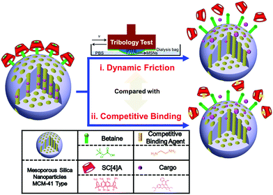
The fabricated activation approaches for the MSNs are depicted in Fig. 1 and the ESI.† Betaines (chemical structure shown in Fig. 1) are installed on the surface of the aminated silica nanoparticles (MSNs-NH2). After loading with a model cargo, Rhodamine B (RhB), p-sulfonato-calix[4]arene (SC[4]A) self-assembles with betaine-modified MSNs (bMSNs) to form the host–guest complex (binding constant: log![[thin space (1/6-em)]](https://www.rsc.org/images/entities/char_2009.gif) K = 4.9)28 and control the loaded cargo release from the nanocontainers (bMSNs ⊃ SC[4]A@RhB). The controlled cargo release is achieved using dynamic friction and competitive binding. Compared with other activation methods, dynamic friction, with its coherent and periodic process, simulates the motion of bone joints and provides a huge contribution to drug delivery to joint cartilage structures. Besides, SC[4]A introduces a large number of charges that can assist the formation of a tenacious hydration layer to reduce friction and the wearing of bone joints and enhance the lubricating properties of the surface. Most importantly, we investigate the mechanism of friction-controlled release and propose a potential lubrication mechanism, which offers an important basis for further designs.
K = 4.9)28 and control the loaded cargo release from the nanocontainers (bMSNs ⊃ SC[4]A@RhB). The controlled cargo release is achieved using dynamic friction and competitive binding. Compared with other activation methods, dynamic friction, with its coherent and periodic process, simulates the motion of bone joints and provides a huge contribution to drug delivery to joint cartilage structures. Besides, SC[4]A introduces a large number of charges that can assist the formation of a tenacious hydration layer to reduce friction and the wearing of bone joints and enhance the lubricating properties of the surface. Most importantly, we investigate the mechanism of friction-controlled release and propose a potential lubrication mechanism, which offers an important basis for further designs.
 | ||
| Fig. 1 An illustration of the friction-controlled mechanised drug delivery system. Two types of activation, (i) dynamic friction and (ii) competitive binding, are applied in this system. | ||
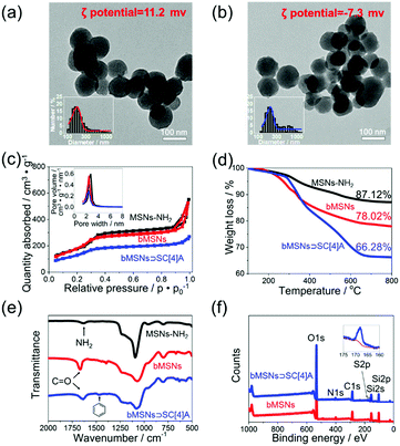
Morphological, thermodynamic, and spectroscopic characterisation data for bMSNs ⊃ SC[4]A, compared with MSNs-NH2 and bMSNs, are shown in Fig. 2. TEM images (Fig. 2a and b) show that the sizes before and after modification are around 100 nm. There is no visible difference in size, which proves that the modification approach does not destroy the structures of the materials. Additionally, the size distribution, taken from dynamic light scattering (DLS), increases because of the formation of hydrated layers, which is displayed in the ESI.† The mesostructures of the MSNs are studied using BET methods (Fig. 2c). Combining these results with the ordered uniform pores observed via TEM, we confirm that all the MSNs used are of the MCM-41 type.2 More details relating to the pore size distribution from three methods are provided in Fig. 2c and the ESI.† TGA curves (Fig. 2d) display an increase in weight loss, proving the successful achievement of both betaine modification and SC[4]A self-assembly on the surface of the MSNs. From FT-IR spectra (Fig. 2e), a new peak was seen to form at 1634 cm−1, corresponding to the C![[double bond, length as m-dash]](https://www.rsc.org/images/entities/char_e001.gif) O stretching vibration of amides, indicating that betaine molecules have been modified on the surface of MSNs-NH2. The self-assembly step does not result in the formation of any new chemical bonds. However, we observe a benzene-based skeleton vibration from SC[4]A, which is located at 1458 cm−1. Further evidence of self-assembly is provided in Fig. 2f, using X-ray photoelectron spectra (XPS), due to the new peak belonging to SC[4]A (more detailed discussion of this section is provided in the ESI†).
O stretching vibration of amides, indicating that betaine molecules have been modified on the surface of MSNs-NH2. The self-assembly step does not result in the formation of any new chemical bonds. However, we observe a benzene-based skeleton vibration from SC[4]A, which is located at 1458 cm−1. Further evidence of self-assembly is provided in Fig. 2f, using X-ray photoelectron spectra (XPS), due to the new peak belonging to SC[4]A (more detailed discussion of this section is provided in the ESI†).
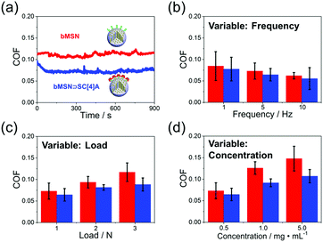
The lubrication properties of both bMSNs and bMSNs ⊃ SC[4]A are evaluated using universal micro-tribology (UMT), as shown in Fig. 3. Overall, the COF is reduced after the assembly of SC[4]A on the surface of bMSNs. Fig. 3a shows a high-intensity continuous friction experiment to investigate the total friction properties. The friction curve of bMSNs ⊃ SC[4]A is much smoother than before the assembly of SC[4]A, which shows the stable lubricating properties of bMSNs ⊃ SC[4]A. According to the hydration lubrication mechanism,27 SC[4]A molecules attract more charges onto the surface of bMSNs to form a tenacious hydrated layer, which improves the lubrication performance. To further determine the lubrication mechanism of bMSNs and bMSNs ⊃ SC[4]A, we also tested the COF values with different frequencies, loads, and concentrations. Generally, there are only slight differences between the various conditions, especially tests involving frequencies and loads. Although we discover a relatively apparent increase in COF with differing concentrations, this is related to the abrasive effects of the MSNs.25 Therefore, we propose that the lubrication mechanism of this system is boundary lubrication according to the Stribeck curve (more details about lubrication states are shown in the ESI†).
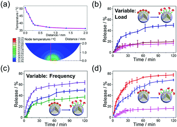
Release profiles and the related mechanism of bMSNs ⊃ SC[4]A@RhB with dynamic friction are examined and compared with release under competitive binding (Fig. 4). The energy conversion as a result of dynamic friction between the surfaces of the joint cavity is simulated and shown in Fig. 4a. A part of the generated mechanical energy is converted into heat, which leads to a significant increase in temperature at the contact area. After a reciprocating movement for 4.5 s, the local temperature at the contact area rises to 50.79 °C (more details are given in the ESI†). Due to an increase in the contact temperature, a significant entropy increase occurs on the surface of the material. The mounting surface chaos directly impairs the ion–dipole interactions of the inclusion complex,26 thereby releasing the molecules from the inorganic container. The speed of the generation of energy, corresponding to the accumulation of temperature, depends mainly on the load and sliding frequency. Therefore, different conditions are employed to investigate the cargo release properties under different loads (Fig. 4b) and sliding frequencies (Fig. 4c). The cargo release profiles with no dynamic friction and a load of 1 N show a similar tendency: only limited cargo (less than 20%) is released after 120 min. Nevertheless, bMSNs ⊃ SC[4]A@RhB are effectively activated under a load of 4 N, with the total cargo release reaching 50% after 120 min. This indicates that the host–guest interaction between SC[4]A and betaine could not be weakened under a mild load (1 N). But under severe friction (4 N), the increase in temperature leads to the destruction of the host–guest interaction, resulting in obvious cargo release. Apparently, the higher the sliding frequency, the faster the temperature accumulates and the quicker the cargo releases. In addition, the cargo release properties of bMSNs@RhB and bMSNs ⊃ SC[4]A@RhB with a competitive binding agent are studied by adding ethylenediamine (Fig. 4d). Compared with the competitive binding approach, the release performance as a result of dynamic friction is much gentler and more controllable, thereby enhancing the efficiency and availability of the loaded cargo.
In conclusion, a smart release system, bMSNs ⊃ SC[4]A, is successfully applied and activated by the movement of simulated bone joints. The inclusion complexes on the surface not only control the release of the cargo but also reduce friction and wear of the joint surface. The mechanism of release is mainly due to the conversion of mechanical energy into heat during the friction process. The hydrated lubrication layer formed by the highly charged structure of the surface significantly reduces the COF, thereby improving the friction and wear properties of the surface. As the friction conditions change, the COF does not change significantly, and the lubrication mechanism conforms to a boundary lubrication model. In addition, we have made appropriate evaluations regarding the toxicity and biocompatibility of bMSNs ⊃ SC[4]A (more details are given in the ESI†), thus demonstrating the biological application prospects of this smart release system in the future.
This study is financially supported by the National Natural Science Foundation of China (Grant No. 51675296), the Ng Teng Fong Charitable Foundation (Grant No. 202-276-132-13), the Tsinghua University Initiative Scientific Research Program (Grant No. 20151080366), and the Research Fund of the State Key Laboratory of Tribology, Tsinghua University, China (Grant No. SKLT2018B08).
Conflicts of interest
There are no conflicts to declare.Notes and references
- Z. Li, J. C. Barnes, A. Bosoy, J. F. Stoddart and J. I. Zink, Chem. Soc. Rev., 2012, 41, 2590–2605 RSC.
- J. S. Beck, J. C. Vartuli, W. J. Roth, M. E. Leonowicz, C. T. Kresge, K. D. Schnitt, C.-T. W. Chu, D. H. Olson, E. W. Sheppard, S. B. McCullen, J. B. Higgins and J. L. Schlenkere, J. Am. Chem. Soc., 1992, 114, 10834–10843 CrossRef CAS.
- Y. Sun, Y. Yang, D. Chen, G. Wang, Y. Zhou, C. Wang and J. F. Stoddart, Small, 2013, 9, 3224–3229 CAS.
- M. Li, H. Yan, C. Teh, V. Korzh and Y. Zhao, Chem. Commun., 2014, 50, 9745–9747 RSC.
- A. Agostini, F. Sancenón, R. Martínez-Máñez, M. D. Marcos, J. Soto and P. Amoros, Chem. – Eur. J., 2012, 18, 12218–12221 CrossRef CAS PubMed.
- D. P. Ferris, Y. Zhao, N. M. Khashab, H. A. Khatib, J. F. Stoddart and J. I. Zink, J. Am. Chem. Soc., 2009, 131, 1686–1688 CrossRef CAS PubMed.
- Y. Sun, B. Yang, S. X. Zhang and Y. Yang, Chem. – Eur. J., 2012, 18, 9212–9216 CrossRef CAS PubMed.
- S. Wu, X. Huang and X. Du, Angew. Chem., Int. Ed., 2013, 52, 5580–5584 CrossRef CAS PubMed.
- F. Muhammad, M. Guo, W. Qi, F. Sun, A. Wang, Y. Guo and G. Zhu, J. Am. Chem. Soc., 2011, 133, 8778–8781 CrossRef CAS PubMed.
- T. Chen, N. Yang and J. Fu, Chem. Commun., 2013, 49, 6555–6557 RSC.
- B. Li, Z. Meng, Q. Li, X. Huang, Z. Kang, H. Dong, J. Chen, J. Sun, Y. Dong, J. Li, X. Jia, J. L. Sessler, Q. Meng and C. Li, Chem. Sci., 2017, 8, 4458–4464 RSC.
- X. Huang, S. Wu, X. Ke, X. Li and X. Du, ACS Appl. Mater. Interfaces, 2017, 9, 19638–19645 CrossRef CAS PubMed.
- D. De and G. M. Mandal, Biomicrofluidics, 2016, 10, 064112 CrossRef PubMed.
- N. John and S. George, J. Drug Delivery Sci. Technol., 2018, 46, 294–301 CrossRef.
- D. Guo, S. Chen, H. Qian, H. Zhang and Y. Liu, Chem. Commun., 2010, 46, 2620–2622 RSC.
- Y. Sun, Y. Zhou, Q. Li and Y. Yang, Chem. Commun., 2013, 49, 9033–9035 RSC.
- R. Hernandez, H. R. Tseng, J. W. Wong, J. F. Stoddart and J. I. Zink, J. Am. Chem. Soc., 2004, 126, 3370–3371 CrossRef CAS PubMed.
- C. Park, K. Oh, S. C. Lee and C. Kim, Angew. Chem., Int. Ed., 2007, 46, 1455–1457 CrossRef CAS PubMed.
- S. Angelos, Y. Yang, K. Patel, J. F. Stoddart and J. I. Zink, Angew. Chem., Int. Ed., 2008, 47, 2222–2226 CrossRef CAS PubMed.
- K. Patel, S. Angelos, W. R. Dichtel, A. Coskun, Y. Yang, J. I. Zink and J. F. Stoddart, J. Am. Chem. Soc., 2008, 130, 2382–2383 CrossRef CAS PubMed.
- K. M. Park, K. Suh, H. Jung, D. W. Lee, Y. Ahn, J. Kim, K. Baek and K. Kim, Chem. Commun., 2008, 71–73 Search PubMed.
- M. Liong, S. Angelos, E. Choi, K. Patel, J. F. Stoddart and J. I. Zink, J. Mater. Chem., 2009, 19, 6251–6257 RSC.
- Y. Yan, T. Sun, H. Zhang, X. Ji, Y. Sun, X. Zhao, L. Deng, J. Qi, W. Cui, H. A. Santos and H. Zhang, Adv. Funct. Mater., 2018 DOI:10.1002/adfm.201807559.
- S. Jahn, J. Seror and J. Klein, Biomed. Eng., 2016, 18, 235–258 CAS.
- T. Sun, Y. Sun and H. Zhang, Polymers, 2018, 10, 513–522 CrossRef.
- Y. Luo and F. J. Millero, Geochim. Cosmochim. Acta, 2007, 71, 326–334 CrossRef CAS PubMed.
- The mechanism of hydration lubrication is converting the friction objectives from the two inorganic surfaces to water film between surfaces. The charged materials can form a strong interaction with water molecules by ion-dipole interactions and hydrogen bond. Therefore, the fiction happens between water films which show an extremely low friction coefficient. See: J. Klein, Friction, 2013, 1, 1–23 CrossRef CAS.
- J. M. Lehn, R. Meric, J. P. Vigneron, M. Cesario, J. Guilhem, C. Pascard, Z. Asfari and J. Vicens, Supramol. Chem., 1993, 5, 97–103 CrossRef.
Footnotes |
| † Electronic supplementary information (ESI) available: Material preparation and characterisation, tribological testing data, controlled release experiments, simulations, and in vitro cytotoxicity studies. See DOI: 10.1039/c8cc10069a |
| ‡ These authors contributed equally to this work. |
| This journal is © The Royal Society of Chemistry 2019 |


