 Open Access Article
Highly dispersed nickel catalysts via a facile pyrolysis generated protective carbon layer†
Sonali
Das
 a,
Ashok
Jangam
a,
Yonghua
Du
b,
Kus
Hidajat
a and
Sibudjing
Kawi
a,
Ashok
Jangam
a,
Yonghua
Du
b,
Kus
Hidajat
a and
Sibudjing
Kawi
 *a
*a
aDepartment of Chemical and Biomolecular Engineering, National University of Singapore, Singapore 119260, Republic of Singapore. E-mail: chekawis@nus.edu.sg
bInstitute of Chemical and Engineering Sciences, A*STAR, 1 Pesek Road, Jurong Island, 627833, Singapore
First published on 8th May 2019
Abstract
Highly dispersed nickel catalysts were synthesized by simple Ni(acac)2 impregnation followed by pyrolysis of organic ligands, which produces a protective carbon coating on the Ni nanoparticles, reducing the metal mobility and sintering. The synthesized catalyst shows high thermal stability and enhanced CO methanation activity compared to the catalyst prepared by the traditional impregnation/calcination method.
Supported metal catalysts hold great significance in catalysis research and industrial catalytic applications involving energy conversion, chemical synthesis etc. Developing highly dispersed supported metal catalysts with a small and controlled metal particle size is of great interest since it causes an increase in the surface area of the active phase and a consequent enhancement in the catalytic activity.1,2 In the past decade, enormous advances have been made in synthesizing highly-dispersed metal catalysts using different synthesis strategies, such as colloidal synthesis,3,4 the sol–gel method,5,6 deposition precipitation,7,8 ion exchange/strong electrostatic adsorption,9 plasma treatment10 or encapsulated structures.11–14 Although these methods are effective, they suffer from the inherent disadvantages of high cost, use of excessive chemicals and processing steps, low yield and difficulty in scaling up.2 As such, the impregnation method still remains the industrially preferred synthesis route due to its simplicity and minimal generation of waste streams. However, the major drawback of the impregnation method is poor metal dispersion and wide particle size distributions resulting from easy agglomeration of the nanoparticles in the drying and calcination steps. The metal sintering problem is especially severe in the non-noble transition metal catalysts like Ni, Cu etc., which have to be supported at high metal loading (5–30%), and impregnation using metal nitrates can result in a wide particle size distribution falling between 1 and 100 nm.8 Hence, there remains a tremendous incentive to design a more general and simple method for the preparation of highly dispersed, supported metal catalysts.
Calcination and reduction are essential steps in the synthesis of supported transition metal catalysts after impregnation. Following impregnation and drying of the metal precursor (nitrate/acetate/acetylacetonate etc.), the catalyst is usually subjected to calcination under high temperatures to remove the organic ligands or surfactants by oxidation or to remove nitrates by decomposition. The supported metal oxide nanoparticles formed after calcination are then converted to metallic nickel by reduction under suitable temperature conditions. Several studies have indicated that metal sintering and redistribution during the calcination and reduction steps is the primary cause of the formation of poorly dispersed catalysts.15,16
In this study, we report a simple and highly effective strategy to synthesize well-dispersed supported Ni nanocatalysts using impregnation by minimizing the metal sintering in the calcination/reduction steps of catalyst synthesis. Using nickel(II) acetylacetonate (acac) as the metal precursor, we show that inert thermal annealing of the catalyst converts the organic acac ligand into carbonaceous deposits on the metal particles and helps in controlling the Ni particle size by reducing the metal mobility during the catalyst pre-treatment. Instead of completely removing the organic content of the precursor by calcination, the Ni loaded catalyst is subjected to a short annealing step under an inert atmosphere that pyrolyzes the acetylacetonate, leaving behind a carbon residue on the nickel particles. This residual carbon can form a protective layer on the Ni nanoparticles that limits their mobility under subsequent high-temperature reduction/reaction treatments and significantly reduces metal sintering and increases metal dispersion. The formation of carbonaceous architectures on colloidally synthesized noble metal nanoparticles has been previously reported to efficiently slow down Ostwald ripening of the metal nanoparticles.17,18 Compared to other methods of nanoparticle synthesis such as colloidal synthesis etc. that involve multiple processing steps, use different chemicals, and are difficult to scale up, this strategy provides a simple approach to produce supported Ni nanoparticle catalysts with high dispersion by a very simple and scalable impregnation method. A similar strategy may be extended to other transition metals like Cu, Co, Fe etc. or noble metals in future studies.
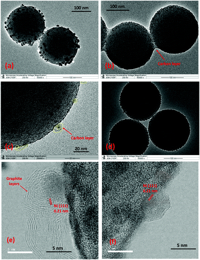
Here, Ni/SiO2 catalysts were synthesized by the impregnation method using nickel(II) acetylacetonate as a metal precursor and Stöber silica as a support (see ESI† for Experimental section). Fig. 1(a) shows the TEM images of the Ni/SiO2 catalyst produced by normal calcination and reduction steps. A broad Ni particle size distribution of 5–40 nm (Fig. S1 in ESI†) is observed with a mean size of 21.8 nm. This relatively large particle size is consistent with the reported literature16,19 and is due to the inhomogeneity of the impregnation preparation method, the high Ni surface loading and the ease of Ni sintering during calcination/reduction.
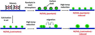
In our proposed strategy, the above calcination step was replaced by a thermal annealing step under an inert atmosphere to pyrolyze the acetylacetonate to a carbon residue instead of completely removing it (Scheme 1). The pyrolysis temperature was set at 450 °C to ensure complete decomposition of the functional groups in the acetylacetonate precursor for a duration of 30 minutes. The thermal decomposition of acac was confirmed through FTIR analysis. In Fig. S2 (ESI†), IR absorptions are observed on the impregnated and dried Ni/SiO2 at 1610, 1530, 1460, 1400, 1260, 930, and 570 cm−1 caused by the ligand in Ni acac. These absorption bands completely disappear in the pyrolyzed Ni/SiO2, indicating either a transformation to carbonaceous species or the complete removal of organic ligands. Further characterization of the state of organic species post thermal treatment are discussed in detail later.
 | ||
| Scheme 1 Schematic of the in situ formation of the carbon residue from pyrolysis of acac ligands and their effect on Ni dispersion. | ||
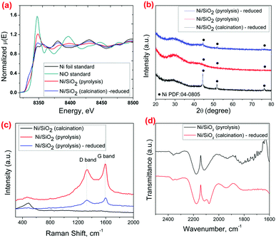
The effectiveness of using the pyrolysis method in preventing Ni sintering during the catalyst preparation is clearly observed through TEM analysis. Fig. 1b and d show the TEM micrographs of Ni/SiO2 after the pyrolysis step and after a subsequent reduction step at 600 °C for 1 hour respectively. In both the catalysts, the Ni particle size distribution is 3–10 nm with a mean size of 4.5 nm and 5.9 nm for the pyrolyzed and reduced catalysts respectively, which is much lower than the Ni/SiO2 (calcination)-reduced catalyst (Fig. 1a). The presence of metallic Ni particles in the pyrolyzed catalyst before reduction (Fig. 1b and e) shows that the Ni gets partially reduced by the product gases (CH4, CO) formed during pyrolysis of acac. Single Ni atoms were also observed in the Ni/SiO2 (pyrolysis) catalyst by HAADF-STEM from the interaction of surface Ni with the carbon layers (Fig. S3, ESI†). XANES analysis (Fig. 2a) of the Ni/SiO2 (pyrolysis) catalyst shows a white-line intensity at 8350.2 eV, which is between the standard Ni0 and NiO spectra, indicating a mixture of metallic Ni0 and Ni2+ states.
The smaller Ni particle size achieved by the pyrolysis step is also supported by XRD analysis and H2 chemisorption (Table S1, ESI†). Fig. 2b shows sharp peaks for metallic Ni at 2θ = 44.5° and 51.8° for the Ni/SiO2 (calcination) – reduced catalyst, while such peaks are barely visible for the Ni/SiO2 (pyrolysis) sample both before and after the reduction step. The crystalline nature of Ni is however observed from the lattice fringes in BF-STEM imaging of both the Ni/SiO2 (pyrolysis) and Ni/SiO2 (pyrolysis) – reduced samples.
The role of the acac pyrolysis on metal sintering was further examined in detail. The presence of residual carbon species on the catalyst after pyrolysis was confirmed through the Raman and TGA analysis. The Raman spectrum (Fig. 2c) for the Ni/SiO2 (pyrolysis) shows clear bands at 1350 cm−1 and 1580 cm−1 characteristic of the D (disordered) and G (graphitic) carbon species,17 showing that the carbon species from acac are not completely removed by the inert pyrolysis step. TGA of the Ni/SiO2 (pyrolysis) catalyst (Fig. S4, ESI†) also shows a weight loss at 250–400 °C and corresponding exothermic peak in the DTA curve, indicating oxidation of residual carbonaceous species. On closer observation by HRTEM and STEM, it is observed that the majority of the Ni nanoparticles in the Ni/SiO2 (pyrolysis) catalyst are coated by a layer of carbon formed during the acac pyrolysis, visible in the form of graphitic rings on the Ni crystals (Fig. 1c and e). The formation of the carbon structures around the Ni nanoparticles can be expected during pyrolysis by the rapid carbonization of the acac ligands around the Ni species.
To demonstrate that the carbon residue creates a protective coating on the Ni particles, CO was used as a molecular probe to identify CO adsorption sites through DRIFTS (Fig. 2d). Ni strongly adsorbs CO, leading to the formation of the Ni-carbonyl species that can be observed clearly in the FTIR spectrum.20,21 When subjected to CO gas (experimental procedure provided in ESI†), the Ni/SiO2 (calcination) catalyst shows a peak at 2075 cm−1 assigned to linearly adsorbed CO on Ni, in addition to the gaseous CO peaks at 2130 cm−1 and 2170 cm−1. On the other hand, the Ni/SiO2 (pyrolysis) catalyst shows no peak for adsorbed CO on Ni, indicating that the surface of Ni is covered with carbon and is hence unavailable for CO adsorption.17,22 These characterizations show that during the inert pyrolysis step, the acac in the metal precursor forms a protective carbonaceous layer on the Ni particles. This carbon layer can effectively act as a physical barrier to inhibit the thermal sintering of the Ni nanoparticles by coalescence and/or Ostwald ripening.
It is interesting to note that such an increase in metal dispersion is not observed by inert thermal pre-treatment using an inorganic metal precursor such as nickel nitrate hexahydrate for impregnation. For the same metal loading, a large mean Ni particle size of ∼41 nm was observed on the Ni/SiO2-nitrate (pyrolysis) catalysts (Fig. S5, ESI†), which was also supported by the XRD results (Fig. S6, ESI†). Similar particle size is observed when the catalyst is subjected to an air calcination treatment. This more strongly supports the role of the carbon layers formed by acac decomposition in limiting the particle growth in our strategy.
While metal sintering during pre-treatment steps is effectively minimized for the Ni/SiO2 (pyrolysis) catalyst, it is essential to maintain the particle size and prevent sintering over time under different chemical environments and elevated temperatures. Thermal stability tests were hence done to examine the sintering resistance of the Ni/SiO2 (pyrolysis) catalysts by exposing the catalyst to hydrogen and air respectively at 600 °C for 6 hours each. TEM analysis (Fig. S7, ESI†) and XRD (Fig. S8, ESI†) of the catalyst after the thermal stability test both under oxidizing and reducing atmosphere shows that there is very little sintering in the process, with the mean particle size remaining around 6.1 nm and 6.3 nm after treatment in H2 and air respectively. A slight broadening of the particle size distribution is observed with an increase in the fraction of Ni nanoparticles in the size range of 5–8 nm. It is to be noted that during these thermal treatments, the carbon layers are partially or completely removed by hydrogen or oxygen, which would make the particles less protected from sintering. Yet, significant sintering over time is not observed which can be attributed to the size homogeneity of the Ni nanoparticles formed in the Ni/SiO2 (pyrolysis), which can reduce the particle growth by Ostwald ripening.1
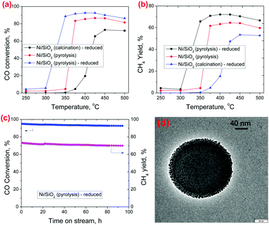
CO methanation was chosen as a model reaction to demonstrate the catalytic performance of the Ni/SiO2 (pyrolysis) catalyst under high-temperature reaction conditions.23Fig. 3a shows the temperature dependent CO methanation activity for the Ni/SiO2 (calcination) – reduced, Ni/SiO2 (pyrolysis) and Ni/SiO2 (pyrolysis) – reduced catalysts, respectively. The CO conversion for the Ni/SiO2 (pyrolysis) is clearly higher than that of the Ni/SiO2 (calcination) – reduced catalyst which can be attributed to a lower size of the Ni nanoparticles. Although single atom Ni species are also observed in the Ni/SiO2 (pyrolysis) catalyst, they have been reported to be unable to hydrogenate CO to CH424 and we expect that only the metallic Ni nanoparticles are the active sites for CO methanation. The activity of the Ni/SiO2 (pyrolysis) catalyst is still low at a lower temperature (≤300 °C), because the Ni nanoparticles are coated with carbon, making many of the sites inaccessible for the reaction. The carbon residue may get partially removed by reacting with the hydrogen and water in the reaction mixture, causing an increase in CO methanation activity at higher temperatures. Some carbon layers were still observed to be retained on Ni in the Ni/SiO2(pyrolysis) catalyst after CO methanation at 400 °C (refer S13 and S14 for detailed characterization, ESI†). In the Ni/SiO2 (pyrolysis) – reduced catalyst, the Ni/SiO2 (pyrolysis) catalyst was subjected to an H2 reduction upfront before reaction, which removed the carbon layers from the Ni nanoparticles (as can be visually observed from BF-STEM in Fig. 1f) and further enhanced the activity. A small amount of carbon residue may still exist after the initial reduction treatment (as can be observed in the Raman spectrum in Fig. 2c for Ni/SiO2 (pyrolysis) – reduced, but not detectable by TGA) and may be responsible for some suppression of the catalytic activity. In spite of that, the Ni/SiO2 (pyrolysis) – reduced catalyst shows much higher CO conversion than the Ni/SiO2 (calcination) – reduced catalyst, which is consistent with its higher Ni dispersion and active site density. A stability test for CO methanation was performed at 400 °C on the Ni/SiO2 (pyrolysis) – reduced catalyst, which showed stable conversion throughout the time tested (Fig. 3c). TEM images (Fig. 3d and Fig. S10, ESI†) and XRD profile (Fig. S11, ESI†) of the spent Ni/SiO2 (pyrolysis) – reduced catalysts after 92 hours of CO methanation show negligible growth in the Ni particle size during the reaction. A slight deactivation observed over time may be caused by the deposition of coke from CO disproportionation reaction, as is observed from the TGA analysis of the spent catalyst (Fig. S12, ESI†). The Ni/SiO2 (calcination) – reduced catalyst showed much lower CO conversion under the same operating conditions (Fig. S9, ESI†).
Overall, we propose a simple and scalable strategy to synthesize supported metal nanoparticles with high dispersion and sinter-resistance at high temperatures by a pyrolysis assisted impregnation method using a metal acetylacetonate precursor. In our study, carbon structures formed on the Ni nanoparticles through acac pyrolysis and carbonation result in lower Ni particle size by preventing metal particle agglomeration, leading to higher catalytic activity and thermal stability, even at a high temperature of 600 °C. The simplicity of the synthesis method gives it great potential for large-scale applications in supported metal catalyst synthesis. Moving forward, the applicability of this strategy for other transition and noble metals and the effect of other organometallic precursors or ligands on the metal sintering properties are being studied.
The authors gratefully thank the Singapore Agency for Science, Technology and Research (A*STAR) AME IRG grant (No. A1783c0016) and the National Environment Agency (NEA) of Singapore (WTE-CRP 1501-103) for generously supporting this work and the scientists at the XAFCA beamline of the Singapore Synchrotron Light Source for XAS measurements.
Conflicts of interest
There are no conflicts to declare.Notes and references
- E. D. Goodman, J. A. Schwalbe and M. Cargnello, ACS Catal., 2017, 7, 7156–7173 CrossRef CAS.
- L. Mo and S. Kawi, J. Mater. Chem. A, 2014, 2, 7837–7844 RSC.
- T. Hyeon, Chem. Commun., 2003, 927–934, 10.1039/B207789B.
- Z. Li, L. Mo, Y. Kathiraser and S. Kawi, ACS Catal., 2014, 4, 1526–1536 CrossRef CAS.
- J. Liu, S. Zou, S. Li, X. Liao, Y. Hong, L. Xiao and J. Fan, J. Mater. Chem. A, 2013, 1, 4038–4047 RSC.
- U. Oemar, M. L. Ang, W. F. Hee, K. Hidajat and S. Kawi, Appl. Catal., B, 2014, 148–149, 231–242 CrossRef CAS.
- Y. Soni, I. Kavya, T. G. Ajithkumar and C. P. Vinod, Chem. Commun., 2018, 54, 12412–12415 RSC.
- J. Cho, L. Xu, C. Jo and R. Ryoo, Chem. Commun., 2017, 53, 3810–3813 RSC.
- L. Jiao and J. R. Regalbuto, J. Catal., 2008, 260, 329–341 CrossRef CAS.
- Z. Wang, Y. Zhang, E. C. Neyts, X. Cao, X. Zhang, B. W. L. Jang and C.-J. Liu, ACS Catal., 2018, 8, 2093–2110 CrossRef CAS.
- G. Wang, S. Xu, L. Wang, Z. Liu, X. Dong, L. Wang, A. Zheng, X. Meng and F.-S. Xiao, Chem. Commun., 2018, 54, 3274–3277 RSC.
- J. Lu, B. Fu, M. C. Kung, G. Xiao, J. W. Elam, H. H. Kung and P. C. Stair, Science, 2012, 335, 1205 CrossRef CAS.
- C. Dai, A. Zhang, M. Liu, L. Gu, X. Guo and C. Song, ACS Nano, 2016, 10, 7401–7408 CrossRef CAS PubMed.
- Z. Bian, Z. Li, J. Ashok and S. Kawi, Chem. Commun., 2015, 51, 16324–16326 RSC.
- X. Y. Gao, K. Hidajat and S. Kawi, J. CO2 Util., 2016, 15, 146–153 CrossRef CAS.
- J. R. A. Sietsma, J. D. Meeldijk, M. Versluijs-Helder, A. Broersma, A. J. V. Dillen, P. E. de Jongh and K. P. de Jong, Chem. Mater., 2008, 20, 2921–2931 CrossRef CAS.
- W. Zhan, Y. Shu, Y. Sheng, H. Zhu, Y. Guo, L. Wang, Y. Guo, J. Zhang, G. Lu and S. Dai, Angew. Chem., Int. Ed., 2017, 56, 4494–4498 CrossRef CAS PubMed.
- M. A. Asoro, D. Kovar and P. J. Ferreira, Chem. Commun., 2014, 50, 4835–4838 RSC.
- J. M. Escola, D. P. Serrano, J. Aguado and L. Briones, Ind. Eng. Chem. Res., 2015, 54, 6660–6668 CrossRef CAS.
- E. T. Saw, U. Oemar, X. R. Tan, Y. Du, A. Borgna, K. Hidajat and S. Kawi, J. Catal., 2014, 314, 32–46 CrossRef CAS.
- D. Li, S. Sakai, Y. Nakagawa and K. Tomishige, Phys. Chem. Chem. Phys., 2012, 14, 9204–9213 RSC.
- S. Das, J. Ashok, Z. Bian, N. Dewangan, M. H. Wai, Y. Du, A. Borgna, K. Hidajat and S. Kawi, Appl. Catal., B, 2018, 230, 220–236 CrossRef CAS.
- X. Jia, N. Rui, X. Zhang, X. Hu and C.-J. Liu, Catal. Today, 2018 DOI:10.1016/j.cattod.2018.11.020.
- M.-M. Millet, G. Algara-Siller, S. Wrabetz, A. Mazheika, F. Girgsdies, D. Teschner, F. Seitz, A. Tarasov, S. V. Levchenko, R. Schlögl and E. Frei, J. Am. Chem. Soc., 2019, 141, 2451–2461 CrossRef CAS.
Footnote |
| † Electronic supplementary information (ESI) available: Experimental procedures, TEM, STEM, XRD, FTIR, TGA, dispersion calculations and reaction performance results available. See DOI: 10.1039/c9cc00783k |
| This journal is © The Royal Society of Chemistry 2019 |


