Low-temperature route to prepare rare earth fluorides in a molten NH4NO3 system: a systematic study on the effects of NaF/Ln ratio and the reaction temperature and time†
Xinyang
Huang
 a,
Liang
Xiong
a and
Xiaoqing
Qiu
 *b
*b
aInstitute of Research on the Functional Materials, Jiangxi University of Finance and Economy, Nanchang, Jiangxi 330013, P.R. China
bCollege of Chemistry and Chemical Engineering, Central South University, Changsha, Hunan 410083, P.R. China. E-mail: xq-qiu@csu.edu.cn
First published on 14th November 2018
Abstract
A low-temperature strategy has been applied to synthesize a host of rare earth fluorides including NaLnF4 and LnF3 (Ln = rare earth) with NaF and rare earth nitrates as initial raw materials in NH4NO3 flux. It is found that the crystal structures and shape evolutions of rare earth fluorides are highly sensitive to the rare earth ions, NaF/Ln molar ratio, reaction temperature and reaction time. Based on their crystallization behavior, the rare earth fluorides can be divided into four groups. Group I (La and Ce)-based LnF3 exhibits the trigonal tysonite type of structure (P![[3 with combining macron]](https://www.rsc.org/images/entities/char_0033_0304.gif) c1). The small particles are generally spherical, whereas the well matured particles have taken on plate-like shape. Group II (Pr and Nd)-based fluorides crystalize in hexagonal LnF3 with changeable shapes (quasisphere, embryonic rod form, short prism, small rods), and high reaction temperature, long reaction time and large NaF/Ln ratio are favorable for the formation of large hexagonal NaLnF4 rods. For group III (Sm, Eu, Gd, Tb, Dy and Ho), the transformation from orthorhombic LnF3 nanopolyhedra to hexagonal LnF3 nanorods occurs at a low reaction temperature when the NaF/Ln molar ratio increases from three to six, whereas the extension of reaction time and the enhancement of reaction temperature induce the production of hexagonal-phased NaLnF4 rod-like particles. Group IV (Y, Er, Tm, Yb and Lu)-based rare earth fluorides prefer to form orthorhombic LnF3 polyhedra at a low NaF/Ln molar ratio of three, whereas increasing the NaF/Ln molar ratio to six produces quasisphere-like cubic NaLnF4 particles, and the extended reaction time and increase in reaction temperature result in hexagonal NaLnF4 rods through Ostwald ripening. The general trend of stable phase and shape evolution of rare earth fluorides can be ascribed to the lanthanide contraction effect and the activation energy barrier to shape transformation.
c1). The small particles are generally spherical, whereas the well matured particles have taken on plate-like shape. Group II (Pr and Nd)-based fluorides crystalize in hexagonal LnF3 with changeable shapes (quasisphere, embryonic rod form, short prism, small rods), and high reaction temperature, long reaction time and large NaF/Ln ratio are favorable for the formation of large hexagonal NaLnF4 rods. For group III (Sm, Eu, Gd, Tb, Dy and Ho), the transformation from orthorhombic LnF3 nanopolyhedra to hexagonal LnF3 nanorods occurs at a low reaction temperature when the NaF/Ln molar ratio increases from three to six, whereas the extension of reaction time and the enhancement of reaction temperature induce the production of hexagonal-phased NaLnF4 rod-like particles. Group IV (Y, Er, Tm, Yb and Lu)-based rare earth fluorides prefer to form orthorhombic LnF3 polyhedra at a low NaF/Ln molar ratio of three, whereas increasing the NaF/Ln molar ratio to six produces quasisphere-like cubic NaLnF4 particles, and the extended reaction time and increase in reaction temperature result in hexagonal NaLnF4 rods through Ostwald ripening. The general trend of stable phase and shape evolution of rare earth fluorides can be ascribed to the lanthanide contraction effect and the activation energy barrier to shape transformation.
Introduction
Rare earth fluorides have recently attracted substantial interests due to their conspicuous luminescence, ferromagnetism, insulating/magnetism properties and potential applications in solid state lasers, energy converters and 3D flat panel displays.1–11 The crystalline structures and chemical and physical properties of rare earth fluorides can normally be determined by the synthetic techniques and experimental variables including the type and the composition of crude materials, the reaction temperature and the reaction time.5–8 Thus, it is fundamentally necessary and important to attentively choose a suitable synthetic protocol and manipulate the synthetic conditions accordingly. The low-temperature routes to rare earth fluorides mainly depend on the following methods: solvo-/hydrothermal method, thermal decomposition method, coprecipitation method, Pechini-type sol–gel method, microwave-assisted method, and sonochemical method.2–8,10–15 Unfortunately, these methods generally suffer from the inherent drawbacks of rigid synthesis conditions, exorbitant crude materials and equipments, and substantial environmental issues, which are still far from the industrial produce. Encouragingly, the molten-salt route has recently been developed and demonstrated as a facile large-scale technique with simplicity, versatility, low cost, and environmental friendliness.16–21 Moreover, molten NH4NO3 has several inherent superiorities such as abundance in nature, low melting point, and easy deliquescence in water/alcohol system to readily isolate the target product.22–25 Since the reaction temperature required (below 250 °C) in molten NH4NO3 is much lower than that in NaF, NaF-KF and NaNO3 flux,26–28 molten NH4NO3 has been applied to fabricate a host of fluorides such as h-NaYF4,22 h-NaBiF4,23 tetragonal LiYF4,24 and c-BaGdF5.25 Their size and crystalline structure can be controlled extensively through stringent control of the experimental conditions such as the amounts of precursor materials, the reaction temperature and the reaction time. However, this is rather time consuming and has low efficiency; also, it is resource intensive and sometimes generates a degree of serendipity. One promising route that simplifies the synthetic procedure is the integration of sodium and fluorine sources into the same precursor NaF, which might provide a much better control of the synthesis of rare earth materials. Furthermore, it is very important to make a thorough inquiry into the crystallization behavior and to underline the phase composition/morphology evolution rule. Herein, we have demonstrated the use of NaF and rare earth nitrates as unprocessed materials to fabricate rare earth fluorides NaLnF4 and LnF3 (Ln = rare earth) in molten ammonium nitrate system. It is found that the type of the selected rare earth ion and the synthetic variables such as NaF-to-Ln(NO3)3 (referred as NaF/Ln) molar ratio, the reaction temperature and reaction time play a crucial role in the crystal structure, morphology and size of the resultant products. The crystallization characteristics and phase composition/morphology evolution of rare earth fluorides in the molten NH4NO3 system originate from the lanthanide contraction and the energy barrier to form rare earth fluorides.Experimental
Materials
Reagent-grade NaF, NH4NO3, Y(NO3)3·6H2O, La(NO3)3·6H2O, Ce(NO3)3·6H2O, Pr(NO3)3·6H2O, Nd(NO3)3·6H2O, Sm(NO3)3·6H2O, Eu(NO3)3·6H2O, Gd(NO3)3·6H2O, Dy(NO3)3·6H2O, Tb(NO3)3·6H2O, Ho(NO3)3·5H2O, Er(NO3)3·5H2O, Tm(NO3)3·5H2O, Yb(NO3)3·5H2O and Lu(NO3)3·3H2O powders were used to synthesize rare earth fluorides.Synthetic procedures
The starting materials NaF, NH4NO3 and Ln(NO3)3·xH2O (Ln= rare earth) were thoroughly mixed. The mixtures were put into 15 ml capacity crucibles. After the lids were tightly closed, the crucibles were placed in an oven. The tank was sealed and treated at designated temperature for designated time in an oven and then cooled to room temperature naturally. The detailed synthetic conditions including NaF/Ln and NH4NO3/Ln molar ratio, the reaction temperature and reaction time are summarized in Tables S1–S5, ESI.† After washing several times with deionized water and ethanol, the precipitates were dried at 70 °C for 12 h in vacuum.Characterization
The phase structures and purities of the rare earth fluorides were examined by X-ray powder diffraction (XRD) characterization on a Bruker D8-Advance diffractometer with graphite-monochromatized CuKα radiation (40 KV/60 mA, λ = 0.1541 nm). The size, morphology and chemical compositions of products were determined by a transmission electron microscope (TEM, JEOL2010) operating at 200 kV and a JSM 6700F scanning electron microscope (SEM) equipped with the energy dispersive X-ray spectrum (EDS). Structural information was obtained by a high-resolution transmission electron microscope (HRTEM).Results and discussion
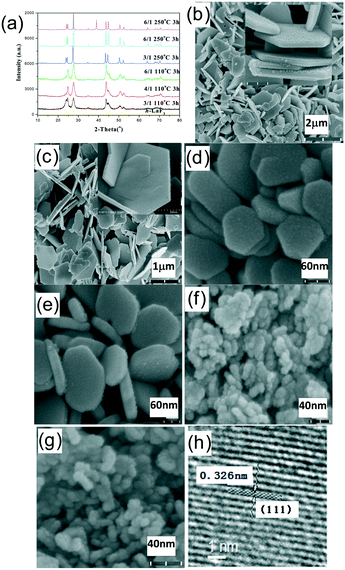
As described below, the phase composition and the morphology evolution of the resultant rare earth fluorides are highly dependent upon the type of chosen rare earth ion and the experiment parameters including the NaF/Ln molar ratio, reaction temperature and time. Accordingly, the as-obtained rare earth fluorides can be divided into four groups, i.e., group I (La and Ce), group II (Pr and Nd), group III (Sm, Eu, Gd, Tb, Dy and Ho) and group IV (Y, Er, Tm, Yb and Lu). The crystallization behaviour and crystal structure/shape evolution rule will be investigated in detail as follows.For group I, rare earth fluorides tend to crystallize into a trigonal tysonite-type structure and are insensitive to the NaF/Ln molar ratio, reaction temperature and reaction time. In contrast, the morphologies and sizes of the resulting fluorides are highly dependent upon the synthetic conditions (shown in Fig. 1, S1, and Table S1, ESI†). As for the NaF/Ln value of three, the increased reaction temperature and prolonged reaction time drove these quasispherical particles to evolve into large flakes with smooth end plane, followed by increase in size (Table S1, ESI†). In contrast, the NaF/Ln molar ratio of six induces shrinkage in the size (Table S1, ESI†), which may have resulted because excess NaF remarkably increases the crystallization temperature and thus hinders the growth. The high-magnification TEM image of the relatively small particles indicates clear fringes of 0.326 nm (Fig. 1h), corresponding to the distance between the neighbouring (111) planes of h-LaF3.
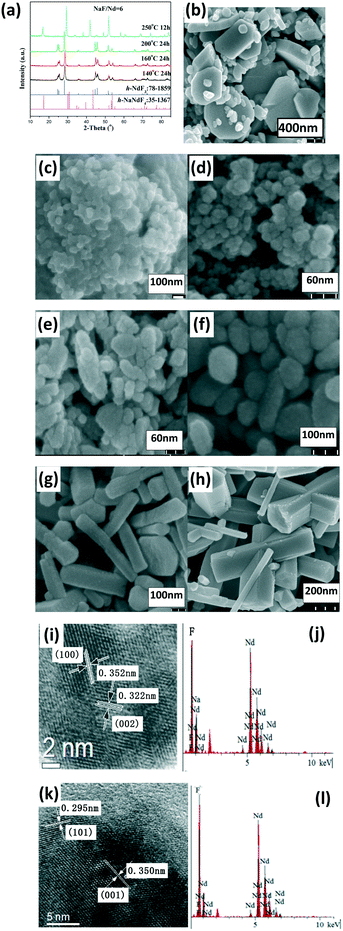
Regarding the NaF/Ln molar ratio of three, the resultant group II (Pr and Nd) fluorides exhibited a hexagonal LnF3 phase (h-LnF3). A low reaction temperature or short reaction time resulted in some small h-LnF3 nanospheres, whereas the increased reaction temperature and prolonged reaction time resulted in large h-LnF3 rods with hexagonal end along with some small nanoparticles (Fig. 2, S2 and Table S1, ESI†). With the NaF/Ln molar ratio of six and gradual increase in the reaction temperature from 100 °C to 200 °C, the product still maintained the nature of the h-LnF3 phase, whereas the morphologies evolved as follows: quasisphere → embryonic rod form → short prism → small rod → large rod (Fig. 2 and S2, and Table S1, ESI†). Interestingly, the increased reaction temperature substantially improved the size and the ratio of the length to the diameter. Unlike group I, h-NaLnF4 was detected in severe synthetic conditions (large NaF/Ln molar ratio of six, high temperature and long reaction time (Fig. 2 and S2a, ESI†)). The relevant morphologies are mainly large hexagonal rods with relatively smooth end and side faces as well as small hexagonal nanorods (Fig. 2 and S2, ESI†). Taking Nd for instance to determine the crystal structure of the large and small rods, the fringe distances (d-spacing) of small rods are 0.60 and 0.37 nm in the HRTEM image (Fig. 2j), corresponding to the distance between neighbouring (100) and (002) planes of h-NdF3 (JCPDS No. 078-1859). The EDS spectra (Fig. 2g) show that they only contain Nd and F, whereas HRTEM images (Fig. 2k) and EDS spectra (Fig. 2l) of the large rods illustrate that the distances between the adjacent lattice fringes of 0.350 nm and 0.295 nm match well with the d101 and d101 spacings of h-NaNdF4 (JCPDS card No. 35-1367) and the existence of Na, Nd and F. Thus, it can be concluded that small rod-like particles belong to h-NdF3, whereas large prisms are ascribed to h-NaNdF4.
As far as group III and group IV are concerned, the crystallographic structures and the shapes and sizes of the resultant products are closely associated with the NaF/Ln molar ratio, reaction temperature and reaction time (Fig. 3–5, S3–S13, and Tables S2–S5, ESI†). We took Y as an example to study the role of the experimental parameters including the NaF/Ln molar ratio, the reaction temperature and the reaction time for phase structure, morphology and size of the products, which will be discussed in detail as follows.
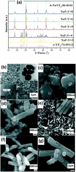
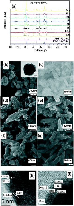
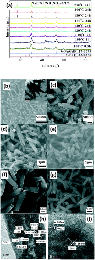
The as-prepared products with NaF/Y molar ratio of three exhibit the same structure as orthorhombic (o-) YF3 (JCPDS No. 74-0911) (Fig. 3a). The samples obtained after 2 h at 100 °C exhibit the shape of polyhedra with ca. 120 nm size (Fig. 3b). The HRTEM image indicates that the fringe distances (d-spacing) are 0.311 and 0.372 nm (inset Fig. 3b), corresponding to the distance between neighbouring (111) and (011) planes of o-YF3 (JCPDS No. 041-0796). Due to the increased temperature of 250 °C, quite a few nanoparticles grew to form large polyhedral particles with ca. 500 nm mean size (Fig. 3c). When the NaF/Y molar ratio was four, the resultant products were a mixture of h-NaYF4 and o-YF3 (Fig. 3a, Table S2, ESI†), and h-NaYF4 exhibited prismatic microrods with diameter of 3.0 μm in length and diameter of ca. 0.8 μm (Fig. 3d). The increased NaF/Y molar ratio of five and above induced the disappearance of the polyhedra o-YF3 (Fig. 3ef, and Table S2, ESI†). Conversely, upon further increasing NaF/Y molar ratio to eight, the prisms grew in an incomplete manner and their length and diameter decreased to 2.5 μm and 0.6 μm (Fig. 3g), respectively. The variation of the NH4NO3/Y molar ratio hardly changed the inherent nature of the hexagonal system, rod-like in shape, and the average diameter of the rod increased, whereas the average length exhibited a significant downward trend when the NH4NO3/Ln molar ratio increased from five to eight and ten (Fig. S3 and Table S3, ESI†). Moreover, the resulting products after 20 min at 100 °C exhibited pure c-NaYF4 (JCPDS No. 28-1192 card) quasisphere-like particles with an average diameter of 120 nm and coarse surfaces (Fig. 4a, b, Table S5, ESI†). The determined interplanar distances of 0.311 nm and 0.280 nm agreed well with (111) and (200) lattice fringes of c-NaYF4 phase (Fig. 4h). When the time was extended to 1 h, the obtained sample exhibited two distinguished particle shapes, that is, quasisphere-like particles and large rods, which was in good agreement with the presence of two phases observed by X-ray powder diffraction (Fig. 4a). The interplanar spacings of 0.295 nm and 0.350 nm of the rod-like particles were indexed as (101) and (011) lattice fringes of h-NaYF4 phase (Fig. 4i). This indicates that rod-like particles belong to the h-NaYF4 phase. A stepwise extension in the reaction time to 24 h and the gradual increase in the reaction temperature from 120 °C through 140 °C to 160 °C resulted in further decrease in the quasisphere-like c-NaYF4 particles and pronounced growth in the h-NaYF4 rods (Fig. S4 and Table S4, ESI†). The quasispheric c-NaYF4 particles were not observed when the reaction temperature was increased to 200 °C (Fig. S5g, ESI†), which was in agreement with the results of the XRD pattern (Fig. 4a). It is suggested that the cubic-to-hexagonal phase conversion is accompanied by dissolution–recrystallization process to minimize the surface energy of the system and Ostwald ripening propels the quasisphere-like particles to convert into rods at the consumption of smaller nanoparticles as well as enhanced sizes.
It should be pointed out that the resultant LnF3 product of group III and IV with a low NaF/Ln molar ratio of three crystallized in the orthorhombic (o-) system, which is distinct from trigonal LnF3 of groups I and hexagonal LnF3 of group II (Fig. S6, S7 and Table S5, ESI†). The low reaction temperature (100 °C) and short reaction time (20 min) produced small nanopolyhedra (Fig. S5, Table S5, ESI†). The increased reaction temperature (250 °C) and extended reaction time (24 h) caused part of the nanopolyhedral particles to transform into large polyhedra (Y, Ho, Er, Tm and Lu), flakes (Sm, Eu, Gd Tb and Yb), or mixed polyhedra and flakes (Dy) (Fig. S6–S8 and Table S5, ESI†). When referring to high NaF/Ln molar ratio of six, all the fluorides of group III and IV with high temperature and long time are present as large rods (Fig. S7 and Table S5, ESI†). Under low reaction temperature (100 °C) and short reaction time (20 min), group III (Sm, Eu, Gd, Tb, Dy and Ho)-based samples were shaped like nanorods (Fig. S9, ESI†). In Eu-based fluorides, the interplanar distance of 0.357 nm observed was consistent with (200) plane of h-EuF3 (Fig. S9k, ESI†), suggesting that the sample is made up of h-EuF3, which is in accordance with the XRD results (Fig. S9 and Table S5, ESI†); HRTEM images of Gd-containing samples reveal the presence of two sets of lattice fringes (Fig. 5h). The interplanar distance was determined to be 0.311 nm, which was associated with the (110) plane of h-NaGdF4, indicating that these rods grow along 001 orientation, whereas the definitive signature of h-GdF3 was also observed. Thereby, in practice, these rod-like products comprise h-GdF3 and h-NaGdF4, which is in agreement with the XRD observations. In contrast, similar to Y-based samples, Er- and Tm-fluorides tended to generate cubic-phased quasispherical c-NaLnF4 particles, as proved by HRTEM images and XRD (Fig. S8–S10, ESI†).
Notably, the evolution in the crystal phase and shape of NaLnF4 (such as Er, Tm and Yb) is similar to that of NaYF4 (Fig. S11–S13 and Table S5, ESI†). The temperature for cubic-to-hexagonal phase complete transition can be dependent upon the chosen rare earth ion and the values are 200 °C, 140 °C and 140 °C after 24 h for Y, Er and Tm, respectively, whereas the temperature and time for all the group III-based h-LnF3 phases to transform to h-NaLnF4 are much lower than that for the total phase conversion of group IV-based fluorides. Broadly speaking, the smaller the radii, the higher the temperature for phase transformation. This behavior can be related to a high trend towards electron cloud distortion of the rare earth ions with large ionic radii due to increased dipole polarizability, which is beneficial for hexagonal structures.29
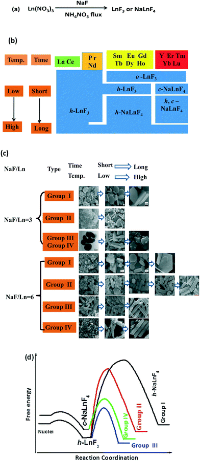
Taken together, the rare earth fluorides LnF3 and NaLnF4 were synthesized by a low-temperature route with NaF and rare earth nitrates as precursor materials in a molten ammonium nitrate system (Fig. 6a). Moreover, the stable crystal structure and shape evolution of the resultant products can be adjusted by the choice of rare earth elements and crystal growth conditions (NaF/Ln molar ratio, reaction temperature and reaction time) (Fig. 6b and c). For the Na/Ln molar ratio of three, the lanthanide contraction effect depends upon the stability of the resultant rare earth fluorides.30–33 Light Ln3+ ions (group I and II) with larger ionic radii favour a large ligand number of eleven, as corroborated by the eleven fluoride ions that surround each Ln3+ ion in trigonal LaF3-type and hexagonal structures. In terms of heavy Ln3+ ions (from Sm to Tm, Lu), the effects of cation size and polarizability induce the crystal structure to feature lower coordination numbers of nine and the orthorhombic YF3-type is the preferred structure.29 When referring to NaF/Ln of six, low temperature and short reaction time, lanthanide contraction still plays a predominant role. For group I, II and III, rare earth fluorides adopt the hexagonal LnF3 structure. Additionally, group IV-based fluorides tend to form cubic NaYF4 fluorite structures with even low ligand number of eight. Interestingly, increasing the NaF/Ln molar ratio from three to six induces the structure of group III-based LnF3 to convert from orthorhombic LnF3 to hexagonal LnF3. This is related to the amount of fluoride ions in the molten system. The shortage of the fluoride ions (NaF/Ln of three) tends to result in the stable orthorhombic phase with a low ligand number of nine, whereas the hexagonal structure with a large ligand number of eleven is the preferred phase in excess of fluoride ions (large NaF/Ln of six).34 It is well accepted that rare earth fluorides with low temperature and short time are thermodynamically metastable species, whereas high temperature or long time should exhibit kinetic predominance, implying that there is a kinetically prohibitive free energy barrier (i.e., a high activation energy).19,35 A simplified illustration of the reaction free energy curve is demonstrated in Fig. 6d. Initially, the reaction between NaF and Ln(NO3)3 in molten NH4NO3 system goes through a low activation energy path and produces h-LnF3 or c-NaYF4. Then, the level of difficulty in the second stage highly depends on the kinetic barrier to the formation of h-NaLnF4. For group I, the kinetic barrier is simply too high to be overcome in the present experimental condition and h-LnF3 is stable in the present condition. Similarly, the very high activation barrier to generate hexagonal group II-based NaLnF4 will make this phase conversion kinetically prohibitive under drastic conditions (high reaction temperature and long reaction time). In contrast, group III-based h-LnF3 compounds go through a relatively low-activation path and readily convert to h-NaLnF4 rods. It is worthwhile to note that for group II and III, rod-like h-NaLnF4 species are formed directly from h-LnF3 because c-NaLnF4 is not as stable as h-LnF3. Regarding group IV, quasispherical c-NaLnF4 particles are formed rather than h-LnF3 since c-NaLnF4 is significantly more stable than h-LnF3. Then, the energy barrier to the formation of h-NaLnF4 is so high that c-NaLnF4 is relatively stable. Only under rigorous conditions including high temperature and long time, pure thermodynamically stable hexagonal rods are obtained.
Conclusions
Many rare earth fluorides LnF3 and NaLnF4 were synthesized through the low-temperature route with NaF and rare earth nitrates as raw materials in molten NH4NO3. The crystal structures, morphologies and sizes of the resulting rare earth fluorides are highly sensitive to the species of the rare earth ions and crystal growth conditions including the NaF/Ln molar ratio, the reaction temperature and the reaction time. According to general trend of stable phases and shape evolution of rare earth fluorides, the rare earth elements can be divided into four groups (I: La and Ce; II: Pr and Nd; III: Sm, Eu, Gd, Tb, Dy and Ho, and IV: Y, Er, Tm, Yb and Lu). The resultant group I-based fluorides exhibit the trigonal LnF3 phase with small quasispherical morphology and large regular platelet particles with smooth end planes under large and small NaF/Ln ratios, respectively. The samples of group II obtained under low temperature comprise quasispherical h-LnF3 particles, whereas high reaction temperature and long reaction time result in large h-NaLnF4 hexagonal sheets. Regarding group III and IV, the crystallization behavior is highly sensitive to the synthetic conditions including the NaF/Ln molar ratio, the reaction temperature and the reaction time. The lack of fluoride ions (low NaF/Ln ratio of three) tends to result in o-LnF3 polyhedra or flakes. Also, h-LnF3 (Ln = group III) and c-NaLnF4 (Ln = group IV) exhibit short rod and quasisphere shapes under low reaction temperature (100 °C) and short reaction time (20 min), whereas mixture c- and h-NaLnF4 (Ln = group III and IV) is shaped like nanorods with sharp ends and quasispherical particles. Regarding the large NaF/Ln molar ratio of six, the extension of reaction time and the increase in the reaction temperature cause h-LnF3 or c-NaLnF4 particles to undergo a dissolution–recrystallization process to convert into large h-NaLnF4 rods. The temperature and time for complete phase conversion required can be decided mainly by the type of rare earth ion. The crystallization nature and shape development is related to the lanthanide contraction as well as the energy barrier to form stable rare earth fluorides. These results substantiate the content of rare earth fluoride material chemistry and conduce to the rules of the growth behaviour.Conflicts of interest
The authors declare no competing financial interest.Acknowledgements
This work was supported by the National Natural Science Foundation of China (61204003), Hunan Provincial Natural Science Foundation of China (Grant No. 2017JJ2326), Train Object Program of Jiangxi Province Young Scientists and Luodi program of Jiangxi Province (No. KJLD13030), respectively.Notes and references
- A. Tressaud and K. Poeppelmier, Photonic and Electronic Properties of Fluoride Materials: Progress in fluorine series, Elsevier Press, 2016 Search PubMed.
- P. Hagenmuller, Inorganic Solid Fluorides: Chemistry and Physics, Academic Press, 1985 Search PubMed.
- B. Zhou, B. Y. Shi and X. G. Liu, Nat. Nanotechnol., 2015, 10, 924 CrossRef CAS.
- H. A. Höppe, Angew. Chem., Int. Ed., 2009, 48, 3572 CrossRef PubMed.
- T. Jüstel, H. Nikol and C. Ronda, Angew. Chem., Int. Ed., 2008, 37, 3084 CrossRef.
- X. M. Li, F. Zhang and D. Y. Zhao, Chem. Soc. Rev., 2015, 44, 1346 RSC.
- M. Haase and H. Schäfer, Angew. Chem., Int. Ed., 2011, 50, 5808 CrossRef CAS.
- X. M. Li, F. Zhang and D. Y. Zhao, Nano Today, 2013, 8, 643 CrossRef CAS.
- A. Gnach and A. Bednarkiewicz, Nano Today, 2012, 7, 532 CrossRef CAS.
- W. F. Yang, X. Y. Li, D. Z. Chi, H. J. Zhang and X. G. Liu, J. Nanotechnol, 2015, 25, 482001 CrossRef.
- G. Y. Chen, H. L. Qiu, P. N. Parasad and X. Y. Chen, Chem. Rev., 2014, 110, 5161 CrossRef.
- X. D. Wang, O. S. Wolfbeis and R. J. Meier, Chem. Soc. Rev., 2013, 42, 7834 RSC.
- W. Zhang, P. Huang, E. Ma, H. M. Zhu and X. Y. Chen, Chem. Soc. Rev., 2015, 44, 1379 RSC.
- S. L. Gai, C. X. Li, P. P. Yang and J. Lin, Chem. Rev., 2014, 114, 2343 CrossRef CAS.
- R. Naccache, Q. Yu and J. A. Capobianco, Adv. Opt. Mater., 2015, 3, 482 CrossRef CAS.
- C. L. Yan, H. G. Zhao, D. F. Perepichka and F. Rosei, Small, 2016, 12, 3888 CrossRef CAS PubMed.
- Y. J. Ma, Z. W. Yang, H. L. Zhang, J. B. Qiu and Z. G. Song, Cryst. Growth Des., 2018, 18, 1758 CrossRef CAS.
- K. Kawashima, J. H. Kim, I. Cheng, K. Yubuta, K. Shin, Y. Liu, J. Lin, G. Henkelman and C. B. Mullins, Cryst. Growth Des., 2018, 18, 5301 CrossRef CAS.
- H. X. Mai, Y. W. Zhang, R. Si, Z. G. Yan, L. D. Sun, L. P. You and C. H. Yan, J. Am. Chem. Soc., 2006, 128, 6426 CrossRef CAS.
- P. Afanasiev and C. Geantet, Coord. Chem. Rev., 1998, 178–180, 1725 CrossRef CAS.
- L. H. Li, J. X. Deng, J. Chen and X. R. Xing, Chem. Sci., 2016, 7, 855 RSC.
- X. Y. Huang, G. H. Hu, Q. J. Xu, X. X. Li and Q. M. Yu, J. Alloys Compd., 2014, 616, 652 CrossRef CAS.
- X. Y. Huang, L. Jiang, Q. J. Xu, X. X. Li and A. Q. He, RSC Adv., 2017, 7, 41190 RSC.
- X. Y. Huang, Opt. Mater. Express, 2014, 4, 2381 CrossRef CAS.
- X. Y. Huang, L. Jiang, X. X. Li and A. Q. He, J. Alloys Compd., 2017, 721, 374 CrossRef CAS.
- S. Suzuki, K. Teshima, T. Wakabayashi, H. Nishikiori, T. Ishizak and S. Oishi, J. Mater. Chem., 2011, 21, 13847 RSC.
- K. Teshima, S. H. Lee, N. Shikine, T. Wakabayashi, K. Yubuta, T. Shishido and S. Oishi, Cryst. Growth Des., 2011, 11, 995 CrossRef CAS.
- S. Suzuki, K. Teshima, T. Wakabayashi, H. Nishikiori, K. Yubuta, T. Shishido and S. Oishi, Cryst. Growth Des., 2011, 11, 4825 CrossRef CAS.
- F. Wang, Y. Han, C. S. Lim, Y. H. Lu, J. Wang, J. Xu, H. Y. Chen, C. Zhang, M. H. Hong and X. G. Liu, Nature, 2010, 463, 1061 CrossRef CAS.
- X. C. Ye, J. Chen, M. Engel, J. A. Millan, W. B. Li, L. Qi, G. Z. Xing, J. E. Collins, C. R. Kagan, J. Li, S. C. Glotzer and C. B. Murray, Nat. Chem., 2013, 5, 466 CrossRef CAS.
- Y. Tian, R. N. Hua, B. J. Chen, N. S. Yu, W. Zhang and L. Y. Na, CrystEngComm, 2012, 14, 8110 RSC.
- M. Wang, Q. L. Huang, J. M. Hong, X. T. Chen and Z. L. Xue, Cryst. Growth Des., 2006, 6, 2169 CrossRef CAS.
- Z. L. Sui, J. Z. Wu, X. Q. Wang, R. C. Dai, Z. P. Wang, X. X. Zheng and Z. M. Zhang, J. Phys. Chem. C, 2016, 120, 18780 CrossRef CAS.
- Q. Zhang and B. Yan, Chem. Commun., 2011, 47, 5867 RSC.
- Y. F. Chen, M. Kim, G. D. Lian, M. B. Johnson and X. G. Peng, J. Am. Chem. Soc., 2005, 127, 13331 CrossRef CAS.
Footnote |
| † Electronic supplementary information (ESI) available: XRD patterns, SEM, TEM, HETEM images of the resulting fluorides under different experimental conditions (NaF/Ln molar ratio, the reaction temperature and the reaction time). See DOI: 10.1039/c8ce01642a |
| This journal is © The Royal Society of Chemistry 2019 |

