Polyoxometalates in dye-sensitized solar cells†
Li
Chen
 ab,
Wei-Lin
Chen
 *a,
Xin-Long
Wang
 *a,
Yang-Guang
Li
 a,
Zhong-Min
Su
 a and
En-Bo
Wang
 *a
*a
aKey Laboratory of Polyoxometalate Science of Ministry of Education, Department of Chemistry, Northeast Normal University, Changchun 130024, P. R. China. E-mail: chenwl@nenu.edu.cn; wangxl824@nenu.edu.cn; wangeb889@nenu.edu.cn
bInstitute of Physical Science and Information Technology, Anhui University, Hefei 230601, P. R. China
First published on 19th November 2018
Abstract
Dye-sensitized solar cells (DSSCs) are the third generation of photovoltaic cells developed by Grätzel and O’Regan. They have the characteristics of low cost, simple manufacturing process, tunable optical properties, and higher photoelectric conversion efficiency (PCE). With an ever increasing energy crisis, there is an urgent need to develop highly efficient, environmentally benign, and energy-saving cell materials. Polyoxometalates (POMs), a kind of molecular inorganic quasi-semiconductor, are promising candidates for use in different parts of DSSCs due to their excellent photosensitivity, redox, and catalytic properties, as well as their relative stability. Following a brief introduction to the development of DSSCs and the potential virtues of POMs in DSSCs, we attempt to make some generalizations about the energy level regulation of POMs that is the underlying theoretical basis for their application in DSSCs, and then we summarize the research progress of POMs in DSSCs in recent years. This is organized in terms of the properties of POMs, namely, electron acceptor, photosensitivity, redox and catalysis, based on the accumulation of our research into POMs over many years. Meanwhile, in view of the fact that the properties of POMs depend primarily on their electronic structural diversity, we keep this point in mind throughout the article with a view to revealing their structure–property relationships. Finally we provide a short summary and remarks on the future outlook. This review may be of interest to synthetic chemists devoted to designing POMs with specific structures, and researchers engaged in the extension of POMs to photoelectric materials.
1. Introduction
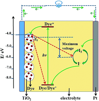
Solar cells are an important way to utilize solar energy resources, and have become the most direct and important choice for the implementation of sustainable development strategies in the world.1–3 The first solar cell in the world was prepared by the American Bell Labs in 1954, which sparked a wave of research in the scientific community.4 After decades of development, solar cells have experienced three stages: the first generation of crystalline silicon solar cells, which is the most mature technology, the second generation of thin film solar cells, and the third-generation new materials/low-cost solar cells.5,6 With the booming development of nanotechnology, research on third-generation solar cells has made significant progress and become one of the main topics in solar cells.Dye-sensitized solar cells (DSSCs), the most representative example of third-generation solar cells, show great potential for high-performance solar cells. A typical structural diagram of a DSSC is shown in Fig. 1, which shows they are mainly composed of photoanode, dye, electrolyte and counter electrode (CE). The basic working mechanism of the DSSC is as follows: firstly the dye molecule absorbs sunlight, leading the ground state electrons to jump to the excited state, and then the electrons in the excited state are injected into the conduction band (CB) of TiO2 (or other semiconductor), by which means the electron–hole separation of the dye molecule is realized. Finally, the electrons of the CB pass through the semiconductor to the outer circuit, and meanwhile the electrolyte reduces the oxidation state dye to complete the regeneration of the dye.7 In consideration of its working mechanism, a vast amount of research work has been done on the dyes, photoanodes, electrolytes, and CEs. Over nearly thirty years of effort, the PCE of DSSCs has been increased from 1% to 12.3%, a value that is nearing the commercial indicator of 15%.8–13 Despite the rapid progress in DSSCs, the major challenge for the practical applications of DSSCs resides in how to increase the PCE to over 15% using current technology.14
To address this challenge, four limiting factors need to be explicated. Firstly, electron recombination occurring at the TiO2/dye/electrolyte interface is a key reason hindering efficiency improvement. Secondly, the arrested development of dyes with good stability, strong bonding with TiO2, and strong absorption in the near-infrared region remains a major question. Thirdly, the most commonly used electrolytes generally contain organic solvents and an I−/I3− redox couple, and leakage and volatilization can take place easily in the process of their usage. Iodide is corrosive to a Pt CE and encapsulated materials, which will seriously affect the stability of the solar cells. In addition, the high concentration of the iodine redox couple will absorb the visible light of the absorbing layer, which is very detrimental to improving the PCE of DSSCs. Although solid electrolytes can solve the leakage of liquid electrolytes and the volatilization of organic solvents to some extent, they should not be used to completely make up for the defects of liquid electrolytes.15 Fourthly, the noble metal Pt, usually used as the CE of DSSCs to achieve good efficiency, is very limited in the earth, and its usage will undoubtedly increase the cost of the cells. There is a long way to go to find an alternative CE to obtain a parallel performance with Pt.16
To solve the aforementioned problems, researchers have developed many strategies and methods. In these researches, polyoxometalates (POMs), a class of inorganic molecular clusters with the early transition metals (W, Mo, V, Nb, Ta) in their highest oxidation states, have come to the fore due to their unique physical and chemical properties,17–42 as summarized in Fig. 2. One overwhelming characteristic of POMs is their excellent and strong electron acceptability, which enables them to effectively capture photo-generated electrons in the CB of semiconductors and suppress the recombination of photo-generated carriers. In other words, POMs can promote the transfer of photo-induced carriers, thus significantly improving the photoanode and enhancing the PCE of the DSSCs. Actually, the study of the PCE of materials with the introduction of POMs into semiconductors has aroused extensive interest by scholars since the first introduction of a saturated POM into solution as an electron medium by Choi in 2003.43 Apart from conventional POMs, high-nuclear POM clusters represented by a series of Mo–O clusters, such as {Mo36}, {Mo132}, {Mo154} and {Mo368},29 also have special electronic structures that have been used as good electron acceptors in DSSCs.44,45 Even more remarkably, the lacunary POMs, derived by removing one or more metal octahedra from a saturated structure, will lead to a more negative field, compared with their saturated parents. Therefore, they are highly nucleophilic and possess more outstanding photoelectric properties when used in DSSCs.45,46 Another sterling quality of POMs is their adjustable energy band structure and wide spectral absorption from the ultraviolet to the visible region which makes them superior sensitizers or cosensitizers in DSSCs,47 especially when it comes to heteropolyblues (HPBs).48 Being the reduced state species of POMs, their unique role in DSSCs cannot be overestimated. The absorption spectra of some HPBs have a considerably wide spectral absorption covering the visible or near infrared region, which will dramatically increase the utilization of sunlight so as to promote the PCE of DSSCs.49 In addition, these reduced state species have enriched electrons relative to their oxidation states. It is known that Keggin-type [XMo12O40]n− clusters can be reduced by 12e− (Fig. S1, ESI†).50 In addition, investigations indicate that the unique redox stability of the Keggin structure allows certain POMs from this family to accept up to 24e−,50 which has been proved both in theoretical and in experimental studies, enabling their use in battery cathodes.51 The electronic structure of super-reduced [PMo12O40]27− is shown in Fig. 3.51 Irle et al. found that there is a maximum of six excess electrons in the reduced molecular substructure fragment [Mo3O13H7]7−. Since there are four such substructures in the α-Keggin POM, the super-reduction involves 24 excess electrons.51 The enriched electrons in HPBs can change their UV-vis absorptions and energy levels and can be given much more easily to the conduction band of TiO2. The wide UV-vis absorptions of HPBs can increase the utilization of sunlight by DSSCs. The enriched electrons in HPBs can enable their possible use as electron repositories, and these stored electrons may change the overall electronic structure of the POM molecule, and these further changes in the energy level structure of POMs occur immediately, and are very important for POMs as sensitizers or cosensitizers in DSSCs. The last but not the least of their merits is their adjustable redox potential and reversible redox activity that makes them superior environmentally benign electrolytes and CEs of DSSCs. The introduction of POMs will improve the catalytic activity and the stability of CEs. In recent years, we have carried out a series of research studies on POM-based DSSCs and confirmed their distinct advantages in DSSCs.44,45,52–58
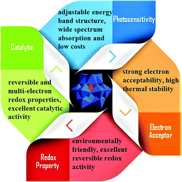 | ||
| Fig. 2 The different properties and functions of POMs, mainly including photosensitivity, electron acceptor, redox and catalytic properties. | ||
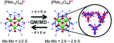 | ||
| Fig. 3 Schematic representation of the reversible molecular and electronic structure changes in [PMo12O40]3− and its reduced state [PMo12O40]27−. (QM: quantum mechanics; MD: molecular dynamics). Reproduced with permission from ref. 51. Copyright (2014) American Chemical Society. | ||
Considering these unparalleled roles of POMs in different parts of DSSCs, in this review, we first elucidate the energy level regulation of POMs based on the accumulation of our research on POMs over many years, because it is an important theoretical basis for their application in DSSCs.20–30 Then we systematically survey the applications of POMs in DSSCs according to their important properties that are organized in order of electron acceptor, photosensitivity, redox and catalysis. Finally, a short summary and remarks on future outlook are provided. One point that should be noted is that the properties of POMs depend primarily on their electronic structural diversity. We therefore keep this point in mind in the relevant parts with a view to revealing their structure–property relationships.
2. The energy level regulation of POMs
2.1 The energy level measurement approaches to POMs
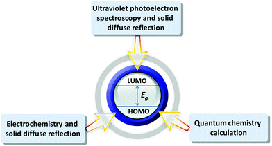
POMs have similar semiconductor properties to metal oxides, such as TiO2 and WO3, which was proved by Hill et al. in 1991.59 Papaconstantinou et al. demonstrated that POMs (mainly produced by the acid condensation of tungstates and/or molybdates) and the aggregation of various metal oxides (formed by stirring and sonication) have similar properties.60 The energy levels of various POMs are different, as determined by their structures, charge density distributions, counter cations, the introduction of transition metals, and so on. The energy level measurements of POMs can help us to further understand the internal electronic structures of POMs.61 POMs with different energy levels may show different electrical and optical characteristics. We can draw the conclusions that some POMs are more suitable to be electron donors under the excitation of sunlight by comparing their electronic structures, while some POMs are more suitable as electron acceptors.Up to now, various methods have been developed to measure the energy level of POMs. Fig. 4 summarizes the main energy level measurement approaches. The first method is the combination of the electrochemistry and solid diffuse reflection, which is a common approach to measuring the energy levels of various POMs. Since the LUMO energy levels of POMs are related to the d-orbits centered on the coordinated atoms, the LUMO energy levels of POMs can be estimated from the applied potential for the first reduction peak.62–64 And the gap of POMs can be obtained from their solid diffuse reflections. The CV of POMs in this method should be tested under stable pH values for the POMs, otherwise pH will have a certain effect on the energy levels.47 The second method is the combination of ultraviolet photoelectron spectroscopy (UPS) and solid diffuse reflection, which can give information about the energy levels of solid POMs.65 This method can be applied to a wider range without being limited by certain pH values of the POMs. However, the kinetic energy of the light excited electrons in the UPS measurement is in the range of 0–40 eV and the number of electrons escaping the depth of the energy interval is small. The surface of the solid material is very sensitive because of the obvious pollution by surface contamination. Moreover, with the rapid change in energy, the surface pollution of solid materials is unavoidable, which has a sensitive effect on the measurement results. Furthermore, UPS is suitable for analysis of homogeneous conductors and conductive semiconductor thin films.66 The detailed experiments and calculations of the above two methods are presented in the ESI.† Quantum chemistry theoretical calculation is another useful method for systematically analyzing the energy levels, electron density, structure and stability of POMs. The energy level calculation by density functional theory (DFT) method is very important for the design and synthesis of new functional POMs. Poblet et al. used the DFT method to calculate the LUMO and HOMO energy levels of POMs to study the effects of different hybrid atoms of Keggin-type POMs on their energy levels and electron properties. The results of the calculation show that the difference in hybrid atoms will directly affect the energy level structure of POMs.67 At present, research on POMs with theoretical calculations can still not perfectly simulate their real environments. So it can only be used as a supplement to the calculation of energy levels. The theoretical calculation results can be combined with the above experimental results to determine the energy levels of POMs. The above methods have been used by many research groups, but the precise measurement of the energy levels for POMs is still a big challenge. Next, we will summarize and compare the results measured by the above three methods.
The energy levels of some POMs or POM-organic hybrid molecules measured by the aforementioned three methods are summarized in Tables 1, 2 and Fig. 4, respectively. There are some slight differences between the results calculated by the two experimental methods, which may arise from the impact of test conditions and the different calculation methods. Fig. 5 shows the frontline molecular orbitals and energy level distributions of the dyes in p-type DSSCs. The HOMO energy levels of the dye molecules are on the whole molecule, especially the carboxyl groups connected with the semiconductor, and the LUMO energy levels of the dye molecules are distributed on the POMs, which are far away from the carboxyl groups.68 In brief, we should fully integrate the advantages of the above methods to obtain more accurate energy level structures for POMs.
| POMs | LUMO/eV | HOMO/eV | E g/eV | Ref. |
|---|---|---|---|---|
| PW12 | −4.73 | −8.05 | 3.32 | 47 |
| SiW12 | −4.55 | −7.81 | 3.26 | |
| H4GeW12O40 (GeW12) | −4.57 | −7.73 | 3.16 | |
| K6CoW12O40 (CoW12) | −4.48 | −7.5 | 3.02 | |
| H3PMo12O40 (PMo12) | −5.23 | −7.74 | 2.51 | |
| H3SiMo12O40 (SiMo12) | −5.23 | −7.82 | 2.59 | |
| H3GeMo12O40 (GeMo12) | −5.01 | −7.58 | 2.57 | |
| H6P2Mo18O62 (P2Mo18) | −5.14 | −7.61 | 2.47 | |
| K6P2W18O62 [K6(P2W18)] | −4.84 | −7.74 | 2.90 | |
| K8SiW11O39 (SiW11) | −4.09 | −7.75 | 3.66 | |
| K10P2W17O61·20H2O (P2W17) | −4.32 | −7.71 | 3.39 | |
| H9P2W15V3 (P2W15V3) | −5.10 | −7.38 | 2.28 | |
| Na10[α-SiW9O34]·18H2O (SiW9) | −3.86 | −7.90 | 4.04 | |
| SiW9Co3 | −3.87 | −6.10 | 2.23 | |
| [C(NH2)3]10[Mn2{Sn(CH2)2COOH}2(B-α-GeW9O34)2] (GeW9-Mn-SnR) | −3.76 | −6.05 | 2.29 | 52 |
| K6[SiWVI11VO40]·7H2O (SiW11V) | −4.31 | −6.98 | 2.67 | 55 |
| [Ni4(H2O)2(PW9O34)2]10− [(PW9)2Ni4] | −3.98 | −6.63 | 2.65 | 69 |
| Na24[Ni12(OH)9(CO3)3(PO4)(SiW9O34)3]·56H2O [(SiW9)3Ni12] | −3.98 | −6.35 | 2.37 | |
| Na25[Ni13(H2O)3(OH)9(PO4)4(SiW9O34)3]·50H2O [(SiW9)3Ni13] | −4.01 | −6.33 | 2.32 | |
| Na50[Ni25(H2O)2(OH)18(CO3)2(PO4)6(SiW9O34)6]·85H2O | −4.01 | −6.24 | 2.23 | |
| [(CH3)4N]5[PW11O39RhCH2COOH]·6H2O (PW11Rh-COOH) | −4.11 | −6.74 | 2.63 | 70 |
| Cs5.5H0.5[SiW11O39RhCH2COOH]·14H2O (SiW11Rh-COOH) | −4.54 | −6.75 | 2.21 | |
| K7PW11O39 (PW11) | −4.08 | −7.82 | 3.74 | |
| TBA8Na2[SiW9O37{Co(H2O)3}]·11H2O (TBA-SiW9Co3) | −4.20 | −5.77 | 1.57 | 71 |
| TBA4[(SiO4)W10MnIII2O36H6]·1.5CH3CN·2H2O (SiW10MnIII2) | −4.17 | −5.57 | 1.40 | |
| TBA3.5H5.5[(SiO4)W10MnIII/IV2O36]·10H2O·0.5CH3CN (SiW10MnIII/IV2) | −4.03 | −5.47 | 1.44 |
| POMs | LUMO/eV | HOMO/eV | E g/eV | Ref. |
|---|---|---|---|---|
| (NH4)42[MoVI72MoV60O372(CH3COO)30(H2O)72] (Mo132) | −4.19 | −5.80 | 1.61 | 45 |
| K6SiW11O39Cu(H2O)·H2O (SiW11Cu) | −4.41 | −7.53 | 3.12 | 58 |
| SiW12 | −4.50 | −8.00 | 3.50 | 65 |
| PW12 | −4.60 | −8.00 | 3.40 | |
| H5PV2W10O40 (PV2W10) | −5.10 | −7.90 | 2.80 | |
| PMo12 | −5.10 | −8.00 | 2.90 | |
| (NH4)6P2W18O62 [(NH4)6(P2W18)] | −5.20 | −8.30 | 3.10 | |
| (NH4)6P2Mo18O62 [(NH4)6(P2Mo18)] | −5.50 | −8.10 | 2.60 | |
| {C(NH2)3}12H4[{Sn(CH2)2COO}2Co2(P2W15O56)2] (PW9-Co-SnR) | −2.27 | −5.39 | 3.12 | 72 |
| Na3K7[{Sn(CH2)2COO}2Co2(B-α-PW9O34)2]·17H2O (P2W15-Co-SnR) | −2.55 | −5.32 | 2.77 | |
| {C(NH2)3}12H4[{Sn(CH2)2COO}2Mn2(P2W15O56)2]·22H2O (P2W15-Mn-SnR) | −3.41 | −6.46 | 3.05 | |
| [Cu(C12H8N2)2]2[V2W4O19]·4H2O (V2W4) | −3.27 | −5.76 | 2.49 | 73 |
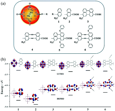 | ||
| Fig. 5 (a) The molecular structures of systems 1–6; (b) the frontier molecular orbital energy level diagram for systems 1–6. Reproduced with permission from ref. 68. Copyright (2013) American Chemical Society. | ||
2.2 The energy level regulation of POMs
The energy levels of POMs have a certain effect on their photoelectric properties, so the most critical investigation is into the regulation of the energy levels of POMs.47 The appropriate POMs can be used in different optoelectronic devices by regulating their energy levels.47,65 Vasilopoulou et al. found that the reduction of each POM cluster was dependent on the nature and energy of its LUMO energy levels, and the relative energy and composition of the LUMO energy levels of POMs correlated quite well with the electron affinity of each isolated Mn+ ion, which was in the order Nb5+ < W6+ < V5+ < Mo6+.65 In addition, when Mn+ is substituted by a more electronegative ion, the LUMO energy levels of POMs will decrease.65 The energy level regulations of POMs mainly include the following aspects, on the basis of our previous research, which are very important for us in choosing the appropriate POMs for application in DSSCs:47(a) The band gap of POMs can be adjusted by changing their structures and compositions: for example, the addition of transition metals into the POMs can decrease the band gap.
(b) POMs based on the W series usually possess larger Eg and higher LUMO energy levels than the Mo series when their structures and central atoms are the same.
(c) Saturation reductions of POMs can induce an increase in band gaps. Meanwhile, the LUMO energy levels of POMs are associated with the central atoms and coordinated atoms.
(d) The smaller oxidation number of the central atom may result in higher LUMO energy levels for POMs with the same structures and coordinated atoms.
(e) Most of the POMs possess larger band gaps and lower LUMO energy levels than those of TiO2.
In addition, the introduction of metal organic ligands into POMs may have a large effect on the energy levels of a POM–organic hybrid molecule system, which have been deduced based on the DFT method as follows:74–78
(i) The HOMO–LUMO energy gaps of the systems will decrease with an increase in the π-spacer size and π-conjugation length.
(ii) The long π-conjugated link slightly decreases the HOMO energy levels, and thiophenol groups can enhance the HOMO energy levels.
(iii) The HOMO energy levels of systems containing electron-withdrawing groups are much lower than those of systems containing electron-donating groups.
(iv) In Zn–porphyrin–POMs, the LUMO energy levels are predominantly populated on POM clusters, which are located far from the anchoring groups.
(v) In metalloporphyrin–POM hybrid complexes, HOMO energy levels are the promotions of the electrons delocalized predominantly on the organic groups and Mo![[triple bond, length as m-dash]](https://www.rsc.org/images/entities/char_e002.gif) N between the organic groups and hexamolybdate clusters, while the LUMO energy levels delocalize over the POM clusters. The electrons may transfer mainly from organic groups to POM clusters.
N between the organic groups and hexamolybdate clusters, while the LUMO energy levels delocalize over the POM clusters. The electrons may transfer mainly from organic groups to POM clusters.
(vi) The strong electron-withdrawing ability of POMs results in a significant effect on the LUMO energy levels of the systems.
The energy levels and the band gaps of most POMs can match well with those of metal oxide semiconductors (MOS), which makes them excellent candidates for DSSCs.45 The match in the energy levels is mainly related to the match between the CB of the semiconductor and the LUMO energy levels of the photosensitizer in DSSCs. Fig. 6 shows the specific electron transport mechanism of POMs with different energy levels in DSSCs. From the left-hand figure of Fig. 6, we can see that the LUMO energy levels of the POMs are higher than the CB of TiO2. So POMs with this electronic structure can be used as photosensitizers. Under light conditions, POMs can produce photo-induced electrons that then pass through TiO2 to the outer circuit. In contrast, from the right-hand figure of Fig. 6, we can see that the LUMO energy levels of the POMs are lower than the CB of TiO2. In this case, the POMs can easily capture the electrons from the CB of TiO2 and can be used as good electron acceptors to accelerate the electron transport in DSSCs.43 So the energy level match of POMs and semiconductor oxides is very critical for the use of POMs in DSSCs.
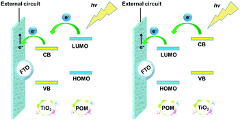 | ||
| Fig. 6 Electron transport mechanism of POMs with different energy levels in DSSCs (CB: the conduction band of TiO2; VB: the valence band of TiO2). | ||
The energy levels of POMs are the basis for studying the application of POMs in DSSCs. The measurement approaches to POMs are very important for us to understand their electronic structures. The basic strategies of energy level regulation can hopefully be used to synthesize new types of functionalized POMs, showing excellent properties in dyes or photoanodes of DSSCs. In the next sections, we will review the strong electron acceptability of POMs in photoanodes and their photosensitivity as dyes based on the energy levels of POMs.
3. POMs as electron acceptors
3.1 Photovoltaic mechanism of POM electron acceptors
The electron recombination occurring in the metal-oxide semiconductor/sensitizer/electrolyte interfaces hinders further improvements in the efficiency of DSSCs.79 So reducing the adverse electron recombination can effectively enhance the performance of DSSCs, which can be realized by employing appropriate POMs in the photoanodes of DSSCs.45 When the LUMO energy levels of POMs are lower than those of MOS, they can act as electron mediators to accept electrons from MOS. This is a spontaneous process in which the electrons transfer from the LUMO energy levels of MOS to the lower LUMO energy levels of POMs, so the excited state photoelectrons can be easily transmitted to the POMs and thence to the external circuit. POMs can accelerate the electron transmissions in MOS and effectively increase the conductivity of the electrodes, simultaneously, so the electron lifetime can be lengthened and the recombination of photon-generated carriers will be restrained. In general, it has been proved in our previous studies that conventional POMs are more suitable as electron acceptors. For example, PW12,80 P2Mo1881 and P2W1882 are three typical and excellent electron acceptors. Later, we will go into more thorough discussions about POMs as electron acceptors to enhance the PCE of DSSCs.3.2 The photoelectric response of POMs
In 2009, Yoon et al. increased the interfacial electron transfer efficiency by changing the nanostructures of TiO2 and incorporating PW12 nanodiscs with TiO2 to act as a favourable electron acceptor. Complementary electron transport from both PW12 and dyes to TiO2 nanodiscs seems to avoid most of the backward electron or hole transfer reactions, thus enhancing the photoelectrochemical efficiencies of DSSCs.80 In 2010, Xu et al. fabricated a series of multilayer films composed of positively charged TiO2 colloids and different anionic POMs or poly(styrenesulfonate) (PSS) so as to obtain steady, sensitive and reproducible photocurrents, and the (PW12/TiO2)3 films got a much higher photocurrent response than (PW12/TiO2)3, (PSS/TiO2)3 or (P2Mo18/TiO2)3 films.81 The experimental results illustrated that PW12 and P2Mo18 could be effective components for an improvement in the photoelectrochemical performance. A nearly 2-fold increase in the photocurrent of the (PW12/TiO2)3 film as compared to that of the (PSS/TiO2)3 film was observed. The electronic transmission mechanism for POMs/TiO2 films is summarized as follows: the photo-induced electrons of TiO2 are excited under ultraviolet light, and then are quickly captured by POMs; finally, the electrons are transferred through POMs to the external circuit. In this way, electron recombination is effectively prevented. So it can be concluded that Keggin and Dawson-type POMs can be used as good electron acceptors in optoelectronic devices.81 On the other hand, Xu et al. inserted Dawson-type POMs and gold nanoparticles into TiO2.82 The transient photocurrent measurements in Fig. 7a demonstrate that the (P2W18/TiO2/P2W18/Au)2 film has the maximum photocurrent response and PCE compared to those of the (P2W18/TiO2)2 film, (PSS/TiO2/PSS/Au)2 film or (PSS/TiO2)2 film. The redox potential of P2W18 is +0.34 V, which matches well with the energy levels of TiO2 (−0.50 V), indicating that the electrons can be transferred from TiO2 to P2W18 and thence to the gold nanoparticles, and the electron transport mechanism can be as shown in Fig. 7b. So the participation of POMs and Au successfully restrains the electron recombinations and promotes the interfacial electrons to shift to the external circuit by means of POMs as electron mediators and Au as an electron conductor junction. Subsequently, Xu et al. successively prepared P2W18 doped CdS,83 [(CH3)4N]5[PW10Mo2O40·4H2O] doped Cu2O,84 and PMo12 doped SnO285 compounds, and the results show that POMs can greatly increase the photoelectric response of the devices.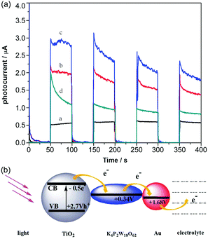 | ||
| Fig. 7 (a) Photocurrent responses of (PSS/TiO2)2 film [black line], (P2W18/TiO2)2 film [red line], (P2W18/TiO2/P2W18/Au)2 film [blue line], and (PSS/TiO2/PSS/Au)2 film [green line] in a 0.1 M Na2SO4 electrolyte; (b) redox potentials and electron-transfer processes. Reproduced with permission from ref. 82. Copyright (2012) The Royal Society of Chemistry. | ||
Furthermore, we reported four types of MOS based photoelectrodes in 2016, which were fabricated by a simple wet chemistry method through bonding TiO2, SnO2, WO3, ZnO with Keplerate-type POM {Mo132}.45Fig. 8a presents the photocurrent changes in the film electrodes when the irradiation is switched on and off. The photocurrent response intensity of the 5% {Mo132}/TiO2 is four times higher than that of pure TiO2. And just as importantly, the LUMO energy level of {Mo132} is lower than the CB of TiO2, so {Mo132} can be used as an electron acceptor to accept electrons from TiO2, which is a favorable exothermic process (Fig. 8b). The energy levels (HOMO/LUMO energy levels) of {Mo132} are in an intermediate position of the band structure of the common MOSs, and therefore {Mo132} can act as a photo-induced electron acceptor or electron donor to enhance the conductivity and the photocurrent response of MOS electrodes, owing to its strong absorption in visible light, high stability and unique photoelectric properties.45 Recent research has shown that POMs can not only improve the photoelectric properties of inorganic semiconductors, but also improve the photoelectric properties of organic semiconductors. More importantly, the effects of different Keggin-type POMs on device performance are different. For example, some Keggin-type POMs with a deeper electron-trap effect will make the release of electrons difficult despite their great facility in accepting electrons from the CB of MOS. However, with an increase in the nucleus of the POMs or the introduction of transition metals, the electronic structures of POMs will be significant changed. Especially for high-nuclear POMs, the highly symmetrical structures and high electron density can accept a large number of electrons without changing their structures. As we know, fullerene (C60) and its derivatives are widely used as electron acceptors in polymer photovoltaic devices. We find that Keplerate-type [K20{(W)W5O21(SO4)}12(VO)30(SO4)(H2O)63]18− (W72V30) is one such good electron acceptor. Because its structure is similar to C60 (Fig. 9a), W72V30 was used as an electron acceptor in place of C60 with a water-soluble PPV derivative as the electron donor. Fig. 9b shows amperometric J–t curves for the photocurrent response of (W72V30/P2)10 film compared to (PSS/P2)10 film. Evidently, the photocurrent response of the (W72V30/P2)10 film is much higher than that of the (PSS/P2)10 multilayer.44
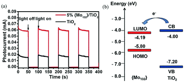 | ||
| Fig. 8 (a) Photocurrent responses with on–off light illumination under simulated AM 1.5 illumination at 100 mW cm−2; (b) energy levels of TiO2 (blue line) and {Mo132} (red line). The arrow represents the direction of electron transfer. Reproduced with permission from ref. 45. Copyright (2015) The Royal Society of Chemistry. | ||
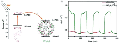 | ||
| Fig. 9 (a) Energy level and electron-transfer process diagram of P2 and {W72V30}; (b) photoelectrochemical responses of (W72V30/P2)10 film (green curve) and (PSS/P2)10 film (red curve) with on–off light illumination from a Xe arc lamp. Reproduced with permission from ref. 44. Copyright (2013) The Royal Society of Chemistry. | ||
In 2011, thin layers of an electrostatically associated adduct formed between [S2Mo18O62]4− and metallopolymers [Ru(bpy)2(PVP)10]2+ or [Ru(bpy)2(CO-P PIC)7]2+ were deposited by Forster.86 Significantly, the Ru-PVP:POM films generate a higher photocurrent (38 ± 1 nA cm−2) than the Ru-Co-P:POM films (8.9 ± 0.8 nA cm−2) or [S2Mo18O62]4− films (9.7 ± 1.1 nA cm−2) under visible irradiation. The magnitude of the photocurrent is consistent with the slow rate at which the catalytic centres are generated within the film, suggesting that substantially high photocurrents could be achieved by enhancing the charge transport diffusion coefficients and removing the ion transport limitation. That is to say, the addition of POMs can accelerate the transmission efficiency of electrons in thin films.86 In 2013, Ruhlmann et al. prepared tetracationic porphyrin [H2TPhN(Me)3P]4+4TsO− and Dawson-type K7[α2-FeP2W17O61] multilayers.87 The results show that the photocurrent of the [α2-FeIIIP2W17O617−-H2TPhN(Me)3P4+]25 film is enhanced by about 25 times compared with porphyrin, which is ascribed to the presence of K7[α2-FeP2W17O61], in that it is a strong acceptor of electrons and can take one electron from the excited porphyrin. The use of K7[α2-FeP2W17O61] helps to transfer the electron via a downhill electrochemical cascade in which more separated charges are taken away, which decreases the charge recombination and simultaneously enhances the photocurrent response.87 In addition, Forster and Ruhlmann have also done a series of related studies to enrich the application of POMs in organic semiconductors.88–92 Gao et al. prepared a photoelectric conversion film consisting of sandwich-type tetracadmium(II) tungstophosphorate [P2W18Cd4(H2O)2O68]10− (P2W18Cd4) and a bichromophore hemicyanine of (E)-1,1-(hexane-1,6-diyl)bis(4-((E)-2-(4-(dimethylamino)naphthalen-1-yl)vinyl)pyridinium)bromide (N6), and the (P2W18Cd4/N6) monolayer film gave a stable cathodic photocurrent that is 2.4- and 6.7-fold as great as those of electrostatically self-assembled monolayer film of (P2W18Cd4/H6) {H6 = (E)-1,1-(hexane-1,6-diyl)bis(4-(4-(dimethylamino)styryl)pyridinium)bromide} and Langmuir–Blodgett monolayer film of analogous hemicyanine (E)-4(2-4-((dimethylamine)naphthalene-1-yl)vinyl)-1-octadecylpyridinium iodide.93 The dominant reason for this experimental result is that POMs have an intrinsic ability of easily accepting electrons and can serve as an efficient electron shuttle between the hemicyanine derivative and the ITO electrode, thereby increasing the efficient dissociation of excitons.
It is known that graphene has a 2D structure with the functional groups on its surface; it has a nearly zero band gap, excellent electron transport capabilities and a high specific surface area, all of which render it a promising support material for POMs.55 We prepared an SiW11V/reduced graphene oxide (rGO)/TiO2 composite film in 2015, which was synthesized by loading SiW11V onto the surface of rGO and then compositing it with TiO2.55 The investigations into the photocurrent response indicate that the photocurrent response of SiW11V/rGO/TiO2 film is 3-fold higher than that of pure TiO2 film, which is ascribed to the wide spectrum absorption of SiW11V and more electrons being injected into rGO from the SiW11V clusters.
3.3 POMs as electron acceptors in DSSCs
The strong electron acceptability of POMs may make it possible for POMs to capture photo-generated electrons in the CB of semiconductors and suppress the recombination of photo-generated carriers, which could significantly improve the photoanode and enhance the PCE of the DSSCs.43 However, the methods of combining POMs and TiO2 are very important due to the fact that POMs have no anchoring groups and thus cannot be directly bonded with TiO2. In 2013, we fabricated a new photoanode with PW12/TiO2 nanocomposite films as the interfacial layer using the layer-by-layer self-assembly technique, and the specific preparation process is shown in Fig. 10a.94 The linear increase in the UV-vis absorbance with the increase in number of layers indicates that each layer of the thin films is uniform and homogeneous (Fig. 10b). The atomic force microscopy (AFM) images in Fig. 10c in three dimensions show the vertical grains of the thin film, and also indicate that the distribution of particles is homogeneous and uniform. When the nanocomposite films are assembled into photoanodes, the performances of the DSSCs with (PW12/TiO2)n interfacial layers are remarkably enhanced compared to those of the no-treatment DSSCs shown in Fig. 10d. In a word, this method can solve the bonding problem between POMs and TiO2. At the same time, the addition of POMs acting as electron acceptors can improve the performance of the photoanode, thereby improving the efficiency of DSSCs. In addition, we prepared PW12-doped TiO2 (PT) using the sol–gel method and mixing the PT and P25 in different proportions (PT/nP25, n = 3, 5, 7, n is the mass ratio of P25 to PW12/TiO2) to assemble the photoanode.95 In 2014, Yang et al. attempted to load TiO2 onto the surface of red K6SiW11O39Co(II)(H2O)·xH2O (SiW11Co) by using a simple one-step hydrolysis reaction method.96 By this method, the absorbing band as well as the photoelectricity response range of TiO2@SiW11Co are extended to the visible range. In addition, the absorption in the UV range is notably enhanced compared with the original TiO2, which is shown in Fig. 11a. More importantly, TiO2@SiW11Co as a photoanode can significantly reduce the recombination of electrons. A schematic illustration of the DSSC is given in Fig. 11b. The reasons for reducing the recombination of electrons are as follows. SiW11Co captures the returning electrons and is reduced to HPB. HPB in this process plays a similar role to SiW11Co, absorbing light and injecting electrons. Meanwhile, the oxidized dye and SiW11Co are regenerated by I−. In addition to the above methods, hydrothermal synthesis is also a useful method to obtain POM-modified TiO2 nanoparticles.97,98 Although we can provide a series of methods to solve the combination of POMs and TiO2, further improvement in the efficiency of DSSCs may be limited by the agglomeration of POMs.99 Our group has developed some strategies to obtain highly dispersive POMs nanoparticles.54,100,101 First of all, we developed a strategy to fabricate highly dispersed and small-sized POM nanoparticles loaded on a TiO2 film by using MIL-101 to prevent agglomeration, and then adopted further calcination to break the metal–organic framework (MOF).54 More active sites of POMs are accessible due to their small size and high dispersion, which facilitates the electronic transmission from photosensitizer to TiO2.54 Secondly, we found that the amount of POMs loaded on a TiO2 film is very small, so we came up with a strategy for breaking POM-based MOFs to obtain high loading amounts of nanosized POM clusters.100 The preparation process of nanometer-sized POMs is shown in Fig. 12a. Calcining POM-based MOFs [Ni(bpp)(H2O)2]3[P2W18O62]·24H2O (bpp = 1,3-bis(4-pyridyl)propane) or H6[Cu3(H2O)6(P2W18O62)2(3-dpye)6]·28H2O (3-dpye = N,N′-bis(3-pyridinecarboxamide)-1,2-ethane) at 500 °C, we can get highly dispersed and small-sized P2W18. The main advantage of this work is that the loading amount (wt%) of P2W18 in the compound can reach 75.67%, as calculated from the data of single-crystal X-ray analysis. But it was only 36.12% in our previous work, showing an enhancement of 109.5%. It can be calculated from Fig. 12b, that the PCE of P2W18·NiO@TiO2 is increased from 5.98 to 7.56%, showing a 26% enhancement compared to the N719-based DSSCs. Fig. 12c shows that P2W18·CuO@TiO2 and P2W18·NiO@TiO2 photoanodes could effectively retard dark current compared with other photoanodes, which also indicates that the small-sized and highly dispersed POMs can retard electron recombination.100 In addition to these two strategies, we synthesized another two kinds of Keggin-type POMs (PW12 and SiW12) with controlled shapes and structures by a micelle-directed method and then composited them with TiO2via calcination to remove the surfactants, subsequently obtaining two kinds of TiO2 composites with highly dispersed and small-sized POM nanoparticles (∼1 nm).101 The nanostructure and quantum size of highly dispersed POMs increase the surface area and active sites, which accelerates the electron transition and retards electron recombination. It is noteworthy that the Voc and Jsc values for a DSSC based on a PW12-Cs2SO4@TiO2 photoanode are higher than those of DSSC devices with other compositions, because POMs can perform effective photoelectrical conversion by avoiding agglomeration and achieving uniform dispersion.101 The above three strategies have been developed to prevent the aggregation of POMs and allow more active sites of POMs to be exposed in the photoanode to improve the efficiency of DSSCs. In addition to these strategies, we have also tried to introduce some special POMs with photoelectric properties into the photoanode of DSSCs. In 2014, a Dawson-type heteropolyacid {P2MoVI18} and its two-electron HPB {P2MoV2MoVI16}-doped TiO2 composites were successfully prepared by a simple sol–gel method and introduced into the photoanode of DSSCs, which resulted in a significant performance enhancement in the DSSCs.102 The results show that doping with HPB and POMs could both suppress the dark current and increase the electron lifetime of DSSCs, and the overall improvements in the efficiency are 24.48% and 17.19% compared to pure P25 for the {P2MoV2MoVI16}-doped and {P2MoVI18}-doped versions, respectively.102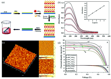 | ||
| Fig. 10 (a) Preparation of a photoanode with a (PW12/TiO2)3 interfacial layer; (b) UV-vis absorption spectra of multilayer films (PW12/TiO2)n on quartz substrates with n = 1–5; (c) AFM images of the (PW12/TiO2)3 interfacial layer; (d) current–voltage curves under AM 1.5 irradiation (100 mW cm−2) of TiCl4-treatment, no-treatment, (PW12/TiO2)n-based (n = 1–5). Reproduced with permission from ref. 94. Copyright (2013) American Chemical Society. | ||
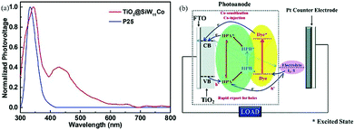 | ||
| Fig. 11 (a) UV-vis spectra of SiW11Co, commercial P25 and TiO2@SiW11Co; (b) schematic illustration of the dye-sensitized photovoltaic cell. Reproduced with permission from ref. 96. Copyright (2014) The Royal Society of Chemistry. | ||
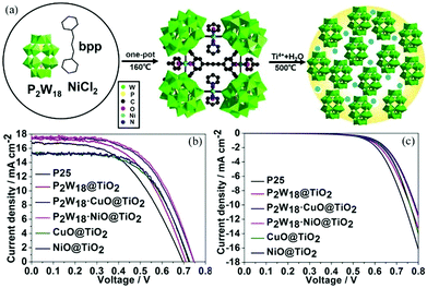 | ||
| Fig. 12 (a) The preparation process of high loading amounts of nanosized POM clusters; (b) the J–V curves of different DSSCs under AM 1.5 radiation (100 mW cm−2); (c) dark current curves. Reproduced with permission from ref. 100. Copyright (2017) Wiley-VCH. | ||
In addition to these, a series of POMs have been assembled into the photoanodes of DSSCs as electron acceptors, which have yielded good results.46,57,103–105 On the basis of the above research, we can clearly ascertain that these classic POMs with Keggin and Dawson geometries are mainly used as electron acceptors in the DSSCs. We can draw the conclusion that the electronic structure of POMs determines their function in DSSCs. Generally speaking, POMs with lower LUMO energy levels than MOS can be applied as electron acceptors in DSSCs, and most of the POMs we have synthesized meet this condition. That is, we can use traditional inorganic molecular clusters as electron acceptors to accelerate electron transfer and reduce the adverse electron recombination of the DSSCs. Perhaps this is the easiest and the most economical way to solve the problems encountered in the photoanodes of DSSCs, which is of great significance to further enhance the PCE of DSSCs. In addition, the size and morphology of POMs are also critical to improving the PCE of DSSCs, as they determine the exposure of active sites on POMs. Finally, the method for combining POMs and MOS is also critical for the introduction of POMs to DSSCs. Given these factors, further explorations are needed.
4. The photosensitive properties of POMs
4.1 An overview of dyes in DSSCs
In DSSCs, the semiconductor is a wide gap material, which can only absorb part of the ultraviolet light to reach very low efficiency.106 So it is necessary to attach a photosensitizer to make full use of the sunlight, so the absorption range of the sunlight can be widened to visible light and infrared light, thus effectively improving the PCE of DSSCs. Dyes play an important role in the PCE of DSSCs, and are the soul of the whole DSSCs. The following conditions need to be met by the dyes of DSSCs:107(1) Dyes should contain functional groups such as carbonyl, sulfonic group or phosphate groups, so that they can be adsorbed firmly on the surface of the semiconductor oxide.
(2) The potential of the oxidation state of the dye should be high enough to accept the electrons in the redox electrolyte.
(3) The energy levels of the excited state of the dye should be matched with the CB of the semiconductor oxide.
(4) Dyes should have higher molar extinction coefficient and high stability.
In the developments in recent decades, many research groups have designed and synthesized a series of new dyes for DSSCs. In general, the dyes can be divided into the following two categories: organic dyes and inorganic dyes. The organic dyes mainly include metal organic complex dyes and pure organic dyes, which have undergone important developments.108–122 Inorganic dyes have better stability for light and heat, lower cost and easier synthesis compared to organic dyes, and have received much attention in recent years. In current studies, inorganic dyes mainly include quantum dots, precious metals nanoparticles, POMs, etc.123–132
For POMs, a most important property is their semiconductor-like feature.59 POMs have a similar energy band structure to metal oxides, and can be considered as inorganic semiconductors. POMs may be an excellent kind of inorganic dye, because their LUMO and HOMO energy levels can be regulated by changing their structures and compositions to produce a good match with the energy levels of semiconductors. The preparation cost of POMs is low, and POMs have good structural stability, thermal stability, solubility, redox stability and a wide range of acid–base stabilities, which are beneficial for improving the stability of the DSSCs. The surface of POMs is easily modified by carboxyl groups, phosphate groups, etc., which is conducive to strong adsorption on the semiconductor surface. POMs have suitable redox potential, which is beneficial for regenerating dyes, increasing the electron injection rate and reducing electron recombination. In addition, POMs have wide spectral absorption. The regulation strategy for the absorption spectra of POMs is as follows. Firstly, conventional POMs can absorb ultraviolet light; when transition metals are introduced into POMs, POMs will have wider absorption in the visible area. Secondly, when POMs are reduced to HPB, POMs will have an intensive absorption in the infrared region and may even realize absorption over the entire spectral regions.
4.2 Studies on the photosensitivity of POMs
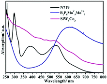
There are many ways to study the photosensitizing properties of POMs, mainly including spectroscopic studies of POMs, the energy levels of POMs, and electron transfer studies of POMs.In conclusion, the analysis and comparison of UV-vis spectra of different types of POMs can help us to select the appropriate POMs for the dyes of DSSCs. However, it is still a challenge to look for POMs with wide absorption in the ultraviolet region, visible and near-infrared areas.
Among these transition metal substituted POMs with higher LUMO energy levels, the researchers found through theoretical calculations that some of them with donor–acceptor (D–A) structures exhibit excellent properties in optoelectronics applications.47,142 The excellent properties, especially their appropriate energy levels, ensure that they have outstanding photosensitivity: for example, the D–A type POMs, α-[PM′9M′′3O40]n− and α-[P2M′15M′′3O62]m− [M′ = W(VI), Mo(VI), and M′′ = V(V), Mo(VI)], calculated by the time-dependent density functional theory method (TDDFT). The D–A structure of the substituted Dawson species, α-[P2M′15M′′3O62]m−, is shown in Fig. 14, and the gray and red octahedra can be viewed as the electron donors and acceptors, respectively. The LUMO energy levels of these trisubstituted POMs are mainly localized on the three substituted transition metal atoms, as calculated by DFT calculations. The tri-substitution effect of the transition metals in Keggin and Dawson-type POMs leads to the charge separations.143 The experimental studies indicate that D–A type POMs with appropriate LUMO energy levels can produce more electrons under light conditions, which can be smoothly transferred to MOS.47
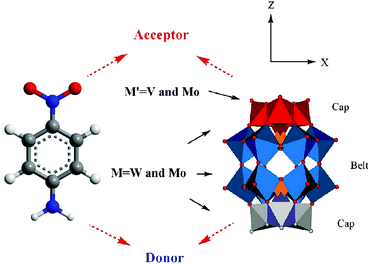 | ||
| Fig. 14 Polyhedral representation of the donor–acceptor substituted Wells–Dawson structure. Reproduced with permission from ref. 143. Copyright (2009) American Chemical Society. | ||
In a word, the energy levels of POMs are very important given their photosensitivity compared with the photoelectric performance of devices assembled by the above-mentioned POMs. POMs as dyes should have higher energy levels than TiO2 or ZnO in order to ensure the higher efficiency of the electron injection.
The SPV coming from the photoexcited excess electrons and holes results in a redistribution of carrier charges. In addition, the SPV of the solid-state semiconductor is derived from the transmission of electrons between the VB and the CB, and sub-band transition between the localized surface state and CB. The formation of the surface state within the semiconductor bandgap is due to the existence of the suspension bond on the surface, the change in atomic environment and lattice defects, etc.144 Xu et al. measured the semiconductor property of three-dimensional all-inorganic POM compounds consisting of [H2W12O42]10− building units and alkaline-earth metal cations (Ca2+, Sr2+ and Ba2+) as linkers by SPV, and drew the conclusion that these compounds have potential applications in photocatalysts and light-to-electricity conversion materials.145 Yang et al. introduced K6[SiW11O39CoII(H2O)]·xH2O into TiO2 and found that the SPV signal of TiO2@SiW11Co was enhanced significantly compared with P25, the results of which show that the light response region of the sample was extended to the visible band.96 We also used SPV to study the photosensitive activity of PW11Rh-COOH, and the results show that the SPV response decreased over the visible range from 420 nm to 520 nm after compositing PW11Rh-COOH with TiO2 (Fig. 15a), indicating that the electrons transferring from POMs to TiO2 result in a reduction in photovoltage in this range.70 SPV investigations into the pure inorganic D–A POM (SiW9Co3) show that there is an obvious light voltage at 332 nm under conditions with bias or without bias, proving that it has a semiconductor nature and produces effective electron–hole separation under the light excitation condition.56 We synthesized a novel carboxyethyltin functionalized sandwich-type germanotungstate [C-(NH2)3]10[Mn2{Sn(CH2)2COOH}2(B-α-GeW9O34)2]·8H2O, and its photosensitivity was studied by SPV. The same conclusion as with {SiW9Co3} can be obtained.52
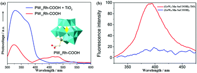 | ||
| Fig. 15 (a) The SPV spectroscopy for PW11Rh-COOH (red line) and composite of TiO2 and PW11Rh-COOH (blue line), the inset is the polyhedral structure of PW11Rh-COOH anion. Reproduced with permission from ref. 70. Copyright (2013) Elsevier; (b) the effect of TiO2 on the fluorescence emission spectrum of (GeW9-Mn-SnCOOH)2 in aqueous solution with a concentration of 5 × 10⁻⁶ mol L−1. Red line, no TiO2 present; blue line, [TiO2] = 0.25 g L−1. Reproduced with permission from ref. 52. Copyright (2014) American Chemical Society. | ||
Fluorescence is another useful method for studying the electron transfer between POMs and other semiconductor materials.146 In general, POMs have a fluorescence emission band upon excitation at a certain wavelength of light, which may be ascribed to the recovery of excited electrons to the ground state. In this process, the optical transition takes place between the different kinds of orbitals or electronic states of different ions.147 In essence, each peak in the fluorescence spectra of POMs is due to the self-activated exciton transfer from the CB to the valence band of these materials. An obvious fluorescence quenching can be observed when a small amount of TiO2 is added into the POM aqueous solution (Fig. 15b), which well confirms that the photoinduced electron transmission is from POMs to TiO2.52 We also obtained the same conclusion by adding some TiO2 powder to {SiW9Co3} powder.56 The electron transfer between wheel-shaped POM {Mo132} and TiO2 has been investigated by the fluorescence method. It is observed that the fluorescence emission band at 500 nm, appearing in the photoluminescence of pure TiO2, is efficiently quenched (upon excitation at 390 nm) on account of the introduction of {Mo132} into TiO2, which demonstrates that the photo-induced electrons may transfer from TiO2 to {Mo132} clusters.45
4.3 POMs as photosensitizers and cosensitizers in solar cells
The photosensitivity of POMs was reported by Yamase in 1982.148 Yamase has studied the light reduction of heteropoly acids containing molybdenum or tungsten as well as the hydrogen production properties based on these light reduction reactions.148 In recent years, some POMs have been used as photocatalysts to oxidize organic pollutants in water and light catalysts or to reduce heavy metal ions in water. Yoon et al. found that ultraviolet light in the range 300–375 nm enables photo-induced electron transfer from the CB of TiO2 to POMs. This promotes the formation of HPB, and the resulting HPB can cooperate in the reduction of methyl orange under visible light. This mechanism of action is similar to the “Z-Scheme” mechanism of a plant. TiO2, loaded into molecular sieves, combines with transition metals and HPBs. These results show that the cooperative effect of TiO2 and HPB can greatly improve the visible light reduction effect of methyl orange.149On the basis of our previous research, we proposed for the first time that POMs may act as a pure inorganic photosensitizer in DSSCs. In 2013, we reported a photosensitizer, PW11Rh-COOH, which not only possesses a smaller Eg and higher LUMO energy levels than TiO2 but also has the right energy levels and wider spectrum absorption. In particular, its anchoring group provides an antenna for POMs to bind onto the surface of TiO2, making it a potential candidate for a photosensitizer of TiO2 (Fig. 16a).70 In Fig. 16b, PW11Rh-COOH sensitized cells exhibit a PCE of 0.141% with a Jsc of 0.402 mA cm−2, Voc of 0.462 V and FF of 0.758 under 100 mW cm−2 irradiation.70 After that, we synthesized a novel carboxyethyltin functionalized sandwich-type POM 1 (GeW9-Mn-SnR), which was designed and synthesized in aqueous solution and applied to a DSSC for the first time.52 As shown in Fig. 17a, an exposed carboxyl group provides a guarantee for the adsorption of GeW9-Mn-SnR on the surface of TiO2. The schematic energy levels of GeW9-Mn-SnR, N719 and TiO2 shown in Fig. 17b indicate that GeW9-Mn-SnR has a fundamental feasibility to be a potentially useful dye for photovoltaic application. In Fig. 17c, GeW9-Mn-SnR displays the primary features of sensitizers in DSSCs, and the efficiency of the solar cell is 0.22%. We were delighted when GeW9-Mn-SnR was employed to assemble a cosensitized solar cell configuration by preparing a GeW9-Mn-SnR-doped TiO2 electrode and additionally adsorbing N719 dyes, and a considerably improved efficiency was achieved through increasing spectral absorption and accelerating electron transport, which was 19.4% higher than that of single N719 sensitization (Fig. 17d).52 In 2015, we systematically studied the energy levels of a D–A type POM (SiW9Co3) and mixed it with N719 as a cosensitizer to assemble a DSSC by a layer-by-layer self-assembly method.47 The theoretical calculations of the D–A type POM (SiW9Co3) show that its HOMO and LUMO energy levels are located on three co-substituted segments and nine W segments, respectively. Under the conditions of illumination, electron transfer from the HOMO to the LUMO energy levels in the molecule will occur. Moreover, the LUMO and HOMO energy levels of the POMs determined by experimental methods are consistent with the basic characteristics of photosensitizers. The overall PCE of the DSSCs was increased to 8.53% through the synergistic effect of POMs and the Ru-complex under an illumination of 100 mW cm−2.47
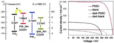 | ||
| Fig. 16 (a) Energy level diagram of POMs and TiO2; (b) the current–voltage characteristics of POM sensitized (red line) and bare TiO2 (dark line) solar cells under simulated AM 1.5 (solid line) (dotted line). Reproduced with permission from ref. 70. Copyright (2013) Elsevier. | ||
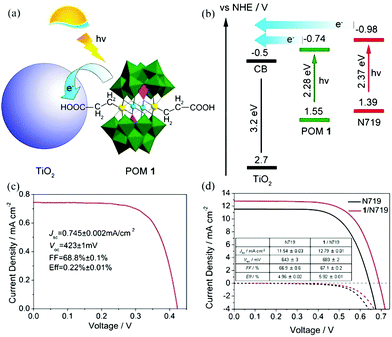 | ||
| Fig. 17 (a) A schematic diagram of a POM as a cosensitizer; (b) schematic energy level of POM and TiO2; (c) the current–voltage curve of GeW9-Mn-SnR sensitized solar cells under AM 1.5 illumination with a dimethyldioctadecyl cation; (d) current–voltage curves under AM 1.5 illumination (solid line) and in the dark (dashed line) of DSSCs with single N719 (dark line) and GeW9-Mn-SnR/N719 (red line) sensitization. Reproduced with the permission from ref. 52. Copyright (2014) American Chemical Society. | ||
In 2014, Yang et al. reported a new photoanode material through loading K6SiW11O39CoII(H2O)·xH2O onto the surface of TiO2. The absorption band as well as the photoelectricity response range of TiO2@SiW11Co were extended to the visible range and the absorption in the UV range was notably enhanced compared with TiO2.96 The SPV signal of TiO2@SiW11Co was enhanced significantly compared with P25, which indicated that after introducing SiW11Co, the light response region of the sample was extended to the visible band. Furthermore, the incident photon-to-electron conversion efficiency (IPCE) confirms that the photocurrent contributions of SiW11Co and N719 are generated from λ = 400 nm to beyond 510 nm, and from 450 to beyond 600 nm, respectively. TiO2@SiW11Co was mixed with TiO2 to assemble the DSSCs. The Jsc value of such a DSSC is as high as 18.05 mA cm−2, which is 64% higher than that of blank samples under 100 mW cm−2 irradiation. In conclusion, the addition of a POM as a cosensitizer to TiO2 can significantly improve the spectral absorption of TiO2 and improve the Jsc of the DSSCs.96 In 2015, we directionally synthesized a new mixed-addenda POM (V2W4). When it was used as a cosensitizer in DSSCs, the light harvesting of solar cells was promoted dramatically.73 A Jsc of 16.71 mA cm−2 and an Voc of 0.691 V were produced with an FF of 0.609, for a PCE of 7.05% for the V2W4/N719-cosensitized solar cell, which is better than for pure N719 (PCE = 5.8%). It may be speculated that the main reason for obtaining such results is that the V2W4-doped TiO2 could absorb more visible light due to the smaller band gap of V2W4 than TiO2, thereby endowing the cosensitized solar cell with more sunlight absorption.73 More recently, we have developed a strategy to prepare a series of long-term stable HPB nanocomposite thin films (classic Keggin and Dawson HPBs) by the combination of improved vacuum thermal evaporation solid-phase reduction (Al as reducing agent) and layer-by-layer self-assembly method.49 The procedure for fabricating multilayer TiO2/POMs films by layer-by-layer self-assembly on an FTO substrate and a schematic illustration of the film structure are shown in Fig. 18a. Fig. 18b shows an obvious photocurrent response of the {TiO2}5/{PW12}6–Al (HPB) film (1.7 μA), which is much higher than that of {TiO2}5/{PW12}6 film. Two possible factors contribute to the result: (1) the PW12 (HPB) acts as a photoresponse component to absorb visible light, and (2) HPBs possess wider spectral photoresponse properties from the ultraviolet to the near-infrared region (300–800 nm). The photocurrent of {TiO2}5/{PW12}6–Al (HPB) film shown in Fig. 18c demonstrates a steady increase when the power intensity of incident sunlight is raised, which is attributed to the increase in the number of photogenerated carriers.49Fig. 18d shows a schematic representation of the charge-transfer process in the film electrode. The results show that the declining amount of POMs or use of the HPBs in the film electrode can make the electrons of HPBs reach saturation rapidly, which is beneficial for enhancing the photocurrent.49
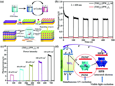 | ||
| Fig. 18 (a) Schematic illustration of the film structure on FTO and the vacuum thermal evaporation solid state reduction POMs schematic diagram; (b) time-resolved photoresponse of TiO2/PW12–Al (HPB) films under visible light (λ > 420 nm); (c) photocurrent density of {TiO2}5/{PW12}6–Al (HPB) film under various power intensities; (d) schematic representation of electron transfer in this electrode. Reproduced with permission from ref. 49. Copyright (2018) Wiley-VCH. | ||
Additionally, a variety of POMs have been applied in p-type DSSCs. In 2016, we used three Keggin-type transition metal-substituted POMs, SiW10MnIII2, SiW10MnIII/IV2 and TBA-{SiW9Co3}, as the pure inorganic photosensitizers of p-type DSSCs, and systematically studied their energy levels and absorption spectra. The three POM-based dyes show overall PCEs of 0.038, 0.029, and 0.027%, respectively, all of which are higher than that of coumarin 343 (0.017%).71 This is the first report of pure inorganic POM photosensitizers of p-type DSSCs. And then, two Dawson-type transition metal-substituted α2-K8P2W17O61(Co2+·OH2)·16H2O ({P2W17Co}) and K7P2W17O61(Mn3+·OH2)·12H2O ({P2W17Mn}) dyes as the cosensitizers in an NiO electrode achieved an overall PCE of 0.0464%, which is the highest value ever reported for inorganic photosensitizers in p-DSSCs.150 The results show that the P2W17Co/P2W17Mn-cosensitized solar cell exhibits a higher PCE than those of P2W17Co or P2W17Mn-sensitized solar cells under the same conditions. The above results prove that POMs are quite qualified for photosensitizers in p-DSSCs.
In summary, numerous efforts have been tried to develop POM-based photosensitizers, including broadening the spectral absorption of POMs, adding anchoring groups to POM structures, and using a cosensitization strategy. The research into POMs-based photosensitizers is still at the new primary development stage. We hope that this part may provide new ideas for researchers working in materials science to develop low-cost and highly efficient inorganic photosensitizers for DSSCs.
4.4 Theoretical calculation studies of POM-based photosensitizers
Quantum chemical calculation is a very important method for further investigating and designing POM-based functional materials,140,151,152 which can reveal the relationships between the structures and properties of POMs. Poblet et al. have undertaken numerous studies in this field. In their research, they mainly study the electronic and magnetic properties of POMs.67,140 In recent years, Su et al. have used DFT and TDDFT methods to study the electronic properties, geometrical structure, spectral properties and photovoltaic properties of Keggin-type polyoxotungstates and Lindqvist-type POMs.In 2013, Su et al. designed a series of POM-based organic–inorganic hybrids with different π-conjugated bridges and investigated their application as sensitizers in DSSCs.68 The molecular structures of systems 1–6 were shown in Fig. 5a. The effect of π-conjugated spacer size and π-conjugation length on the spectra of the designed sensitizers was studied by DFT and TDDFT methods, and the research indicates that system 4 has a wide spectrum absorption, as supported by the UV-vis spectra. The frontier molecular orbital energy level diagrams for systems 1–6 are shown in Fig. 5b. All the HOMO energy levels of the studied systems are delocalized over the organic groups, and extended to the anchoring group, which is helpful to the efficient injection of holes. The LUMO energy levels are localized on the POM cluster, which are far from the anchoring site and can effectively prevent charge recombination. Both HOMO and LUMO energy levels are important for making highly effective dyes of DSSCs, and may provide good evidence to check whether the designed POMs can act as photosensitizers.68 As an extension of their work, in 2015, they designed a series of POM-based organic–inorganic hybrid p-type dyes containing double D–A1–π–A2 chains. The A1 spacers are thiophene, 1,2,3-triazole, 1,3,4-oxadiazole, thienothiadiazole units or their combinations, and the A2 spacer is hexamolybdate.153 It can be concluded that the introduction of thienothiadiazole units is an effective way to improve the light absorption ability of dyes, and inserting thiophene and 1,2,3-triazole as A1 spacers can increase the efficiency of the dyes in DSSCs.153 In 2016, a series of Zn–porphyrin–POM hybrids with different π-linkers were designed as sensitizers in p-type DSSCs and this work gave some theoretical guidance for further enhancing the efficiencies of POM–porphyrin sensitizers.75 In 2014, Su et al. utilized TDDFT methods to discuss the absorption spectra, electronic transition properties, and photovoltaic performance of metalloporphyrin–POM complexes for p-type DSSCs. This was the first report exploring this new kind of complex combining porphyrin with Lindqvist-type POMs as dye sensitizers, which is expected to advance the design of metalloporphyrin–POM hybrid dyes with excellent performance in DSSCs.77 As shown in Fig. 19a, six dyes based on the POM conjugated zinc(II)-centered-porphyrin were chosen to investigate the properties of DSSCs. The absorption spectra of dyes 2–6 with POMs exhibit larger and broader absorptions compared to those of dye 1 without POMs. In order to intuitively describe the nature of the electronic transition, the electronic difference density maps (EDDMs) of dyes 2–6 are shown in Fig. 19b. The results show that there coexist two types of electron transition in the absorption: i.e. the π → π* transition within the porphyrin fragment and the charge transfer from the porphyrin fragment to the POM cluster. This indicates that the POM cluster plays a significant role in charge transfer.77 In 2017, Su et al. studied a series of hexamolybdate-based organic–inorganic hybrids containing double donor–π-linker–acceptor chains through the DFT and TDDFT methods, and this work confirms that the introduction of thiophene is the most effective strategy to improve the absorption and increase the efficiency of dyes in DSSCs.154 Moreover, a series of donor–acceptor–π-bridge–acceptor (D–A–π–A) type hybrids were designed by introducing Lindqvist-type POMs into synthesized dyes, aiming at revealing the impact of POMs on the performance of dyes. The analysis of charge transfer parameters indicated that the introduction of POMs results in a stronger, longer, and tighter charge transfer process.78
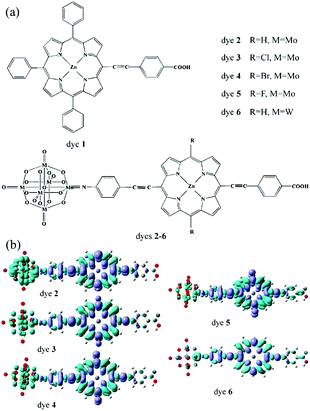 | ||
| Fig. 19 (a) Structure of dyes 1–6; (b) electronic difference density maps of dyes 2–6. Reproduced with permission from ref. 77. Copyright (2014) American Chemical Society. | ||
5. The redox and catalytic properties of POMs in DSSCs
5.1 The redox property of POMs applied in electrolytes of DSSCs
An ideal liquid electrolyte must meet the following requirements: good chemical stability, reversibility of redox, low viscosity, matchable redox potential with the oxidation-state dye and the CB of TiO2, no solubility for dye molecules and photoanode materials.161 In addition, there are also semisolid electrolytes and solid-state electrolytes. The common hardeners of semisolid electrolytes are organic small molecules, organic macromolecules and inorganic nanoparticles.15,162 The ordinary solid electrolytes are inorganic p-type semiconductor materials, such as CuI/CuSCN, organic hole-transport materials and high molecular materials. Furthermore, POMs can have a stable redox state and adjustable redox potentials via changing heteroatoms and coordinating metal atoms without affecting their structures. Furthermore, POMs are soluble and stable in many traditional organic solvents, which makes it possible to detect the redox reaction signals of transition metals in POMs. More importantly, it is possible to inhibit electron–hole recombination on the surface of the photoanode due to the longer transient electron lifetime of POMs. Most POMs have broad and reversible redox potentials, containing multiple unpaired d electrons, which can perform a series of rapid single- and dual-electron reversible redox processes. These unique characteristics endow them with the potential to become candidate electrolyte materials in DSSCs.42,163
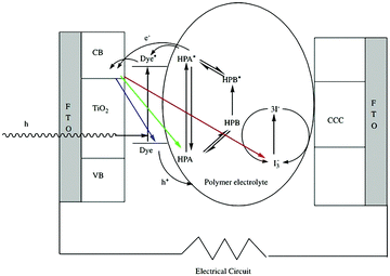 | ||
| Fig. 20 Schematic illustration of the DSSCs. Reproduced with permission from ref. 164. Copyright (2006) Elsevier. | ||
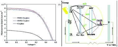 | ||
| Fig. 21 (a) Photocurrent density–voltage curves for DSSCs with POM1-Cu-phen, POM2-Cu-phen and Cu-phen redox couple based electrolytes; (b) a schematic diagram of the interior of a DSSC with POM1/POM2-Cu-phen redox couple based electrolyte. (The black arrow represents the electron transfer; the red dotted line represents the covalent bond; the yellow line represents the represents the electron transfer; the red arrow represents the positive shift in the redox potential of CuI/II). Reproduced with permission from ref. 167. Copyright (2014) The Royal Society of Chemistry. | ||
5.2 The catalytic property of POMs applied in the CE of DSSCs
The good electrocatalytic properties of POMs can make them reversibly gain or lose electrons without changing their structure in DSSCs.42,163 The adjustable redox potential of POMs has attracted wide attention.192 By changing the central heteroatom or the coordination atom in the structure of POMs, the redox potential can be changed obviously.192 Furthermore, POMs, as a kind of molecular oxygen cluster with a natural nanometer size, have a stable structure, high charge and good solubility.32 With an extensive study of POMs, many POMs have shown advantages as electrical catalysts.193 Especially in the field of electrocatalysis, the POM modified electrode shows good electrocatalytic activity.42,163 More importantly, POMs are quite stable in some organic solvents and are environmentally friendly, which make it possible to apply POMs to CEs.
These features mean they will cooperate with the above CE materials so as to enhance the catalytic activity of the CE. Notably, nanomaterials derived from POMs also exhibit excellent catalytic activity as CE materials in DSSCs.
(I) Composite CE materials with POMs and Pt
Pt is the most efficient and stable CE material in DSSCs. POM-based Pt electrodes have better stability and higher catalytic activity by combining the advantages of POMs and Pt, and have exhibited excellent performance in the field of electrical catalysis.196–198 In 2012, we reported a transition metal-substituted polyoxotungstate-modified Pt composite CE which has four advantages: (i) it is inexpensive to use POMs as the modifier; (ii) the modification is easy to handle and the preparation process is simple and economical; (iii) it possesses long-term stability in electrolyte; (iv) this composite electrode exhibits a higher conversion efficiency, higher short current density and open circuit voltage compared with a bare Pt CE. This work was the first report on the use of POM-based multilayer film as a modifier coated on the Pt CE of DSSCs.199 In 2016, Yang et al. prepared an SiW11Cu/Pt composite CE by a screen printing method. The use of SiW11Cu not only reduced the amount of Pt in DSSCs but also increased the synergetic catalytic activity for I3− reduction in CE thanks to the superior catalytic activity of metal-substituted polyoxoanions. The mechanism diagram of the DSSCs is shown in Fig. 22a. The cyclic voltammograms and Tafel polarization curves for Pt and SiW11Cu/Pt CEs are shown in Fig. 22b and c. This example provides good proof of the fact that the addition of POMs can significantly enhance the catalytic activity of CEs.200
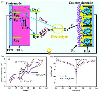 | ||
| Fig. 22 (a) A CE consisting of one layer of SiW11Cu and two layers of conventional Pt nanoparticles; (b) cyclic voltammograms for Pt and SiW11Cu/Pt CEs in 0.01 M LiI, 0.001 M I2, and 0.1 M LiClO4 acetonitrile solutions at a scan rate of 50 mV s−1; (c) Tafel polarization curves of the Cu/Pt and Pt CEs. Reproduced with permission from ref. 200. Copyright (2016) Elsevier. | ||
(II) Composite CE materials with POMs and conductive polymers
In light of the good conductivity, high environmental stability, low cost, and unique optical, electronic and electrochemical properties of conductive polymers, POMs have been introduced into the system to fabricate POM/conductive polymer composite materials as Pt-free CEs for DSSCs by using different methods. In 1997, Romero et al. reported a new class of hybrid electrode by the combination of a conducting polymer matrix with the phosphomolybdate anion and established the function of these hybrid materials as solid insertion electrodes.201 In 2010, Almeida et al. synthesized conducting polyanilines doped with two Keggin-type POMs, which were also used to prepare a new type of CE for DSSCs. These investigations provide evidence for the role of a dopant in enhancing the electrical conductivity of polyanilines.202 In 2013, we successfully fabricated a POM-doped poly(3,4-ethylenedioxythiophene) hybrid film CE by electropolymerization in an environmentally friendly aqueous solution (Fig. 23a). The PCE of the hybrid film CE in a DSSC was almost as high as that in a DSSC with a Pt CE (Fig. 23b). EIS was applied to verify the electrocatalytic activity of different CEs in reducing I3−. Fig. 23c shows the typical Nyquist plot of different CEs, the intercept of the plot and the real axis represent the series resistance (Rs), the arch on the left of the plot represents the Rct and the double capacitance in the electrode and electrolyte interface. In addition, this hybrid film has good electrochemical stability.203
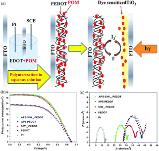 | ||
| Fig. 23 (a) Electropolymerization POM-doped PEDOT film as CEs in DSSCs; (b) photocurrent–voltage curves for DSSCs with APS-SiW11-PEDOT, APS-PEDOT, SiW11-PEDOT, PEDOT, and Pt CEs; (c) electrochemical impedance spectroscopy (EIS) for different CEs. The frequency range explored was 0.01 Hz to 105 Hz, with the ac amplitude perturbed at 10 mV. The applied bias voltage, between two symmetrical CEs, was set at 0 V. Reproduced with permission from ref. 203. Copyright (2016) American Chemical Society. | ||
(III) Composite CE materials with POMs and carbon materials
Carbon materials have good conductivity, high surface area and low price. The composite materials composed of POMs and carbon materials are expected to afford high-performance CEs, having both high conductivity and catalytic activity by combining the advantages of each. In 2014, we successfully synthesized two novel germanotungstates that were subsequently assembled with single-walled nanotubes into composite electrodes (SWNT), as illustrated in Fig. 24a and b. The composite materials markedly increased the electrocatalytic activity of single-walled carbon nanotubes towards triiodide reduction and showed a PCE of 6.32%, which is comparable to that of Pt electrodes (6.29%). It can be seen from the HRTEM that POM is deposited evenly on the carbon nanotubes (Fig. 24c and d).53
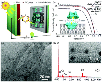 | ||
| Fig. 24 (a) Carboxyethyltin decorated sandwich-type germanotungstate modified carbon nanotubes as CEs in DSSCs; (b) the J–V curves of DSSCs using different CEs; (c) high-magnification HRTEM images of SWNT/GeW9-Cu-SnR; (d) the EDS of SWNT/GeW9-Cu-SnR. Reproduced with permission from ref. 53. Copyright (2014) The Royal Society of Chemistry. | ||
(IV) Composite CE materials derived from POMs
In recent years, POMs have been widely used as precursors for nanocomposites due to their excellent properties. POM-derived nanocomposites can play a good catalytic role in OER, ORR and organic reactions.204,205 Recently, we have prepared a novel Mo2C@NC hybrid by a facile one-step solid-phase synthesis method from inexpensive raw materials (POMs and dicyandiamide), in which molybdenum carbide nanoparticles are homogeneously distributed in a nitrogen-rich carbon matrix (Mo2C@NC). The novel Mo2C@NC hybrid was not only used as a CE in DSSCs, but also showed superior catalytic activity towards I3−/I− as a redox electrolyte. The PCE of the DSSCs with Mo2C@NC as the CE was as high as 6.49%, comparable to that of Pt (6.38%).206 In 2018, we prepared another nanomaterial, Co3O4-WC-CN/rGO (CN is nitrogen-doped carbon; rGO is reduced graphene oxide), as an efficient alternative to Pt for a CE by the high-temperature calcination of an Na6H2W12O40·H2O (H2W12) embedded metal–organic framework in argon gas and air atmosphere.207 The preparation process of Co3O4-WC-CN/rGO, illustrated in Fig. 25a, is economic, non-toxic and simple. The Tafel polarization shown in Fig. 25b is used to further investigate the transferrance properties of the I−/I3− redox couple, indicating that Co3O4-WC-CN/rGO possesses the fastest diffusion rate for the reduction of I3− in the electrolyte. The J–V curves in Fig. 25c represent the curve closest to the average efficiency. For Co3O4-WC-CN/rGO as the CE, a PCE of 7.38% was obtained with a Jsc of 16.27 mA cm−2, Voc of 0.77 V and FF of 0.59, which exceeded the PCE of DSSCs with Pt as the CE.
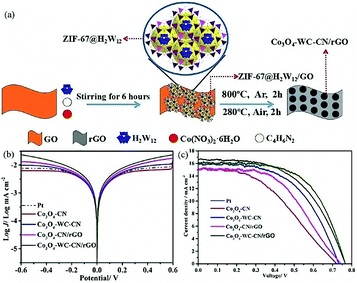 | ||
| Fig. 25 (a) Illustration of the preparation process for Co3O4-WC-CN/rGO; (b) Tafel polarization curves using different materials as CEs; (c) J–V curves of DSSCs using different materials as CEs. Reproduced with permission from ref. 207. Copyright (2018) Elsevier. | ||
6. Concluding remarks and future outlook
POM chemistry has undergone explosive growth since a review by Pope and Müller in 1991,134 and the development of POMs has shifted from a single synthetic chemistry to versatile applications due to their unmatched physical and chemical properties.30–35 Studies on applying POMs to DSSCs have achieved exciting new findings, showing their promise in solving the energy problems of the future. This review has summarized the important work based on our and other groups on the application of POMs in DSSCs. Table 3 lists different kinds of POMs and their applications in different parts of DSSCs, which we believe will provide useful guidance for the development of this important area of research. As evidenced by Table 3, POMs can act as sensitizers and cosensitizers in DSSCs due to their ability to accept electrons on the one hand, and on the other hand to serve as photoanodes due to their ability to provide electrons. In addition, their excellent redox properties enable them to be used as catalysts in the electrodes and electrolytes in DSSCs.192 In short, the strong electron acceptability, adjustable energy band structure, wide spectral absorption, excellent stability, low cost, excellent photoelectric catalytic activity and other characteristics of POMs mean they can be used in different parts of DSSCs to optimize the performance of cells. Our latest research indicates that POMs can form an electric double layer with the cations of raindrops by electrostatic interaction, thus generating electrical signals. In this way, a continuous current can be obtained during charging and discharging with the persistence of raindrops. As such, POMs are expected to be used in the development of solar cells with low cost and high output to generate electricity on rainy days. Additionally, we also found that POMs can be used in a p–n heterojunction piezoelectric device with DSSCs to fabricate transparent-piezoelectric difunctional solar cells. Despite all this promise, there remain some issues that need to be solved for the application of POMs in DSSCs, as discussed below.| Photoanode | Dye | Electrolyte | CE | J sc/mA cm2 | V oc/mV | FF/% | PCE/% | Ref. |
|---|---|---|---|---|---|---|---|---|
| Mo132/TiO2 | N719 | I−/I3− | Pt | 16.78 | 711 | 66.6 | 7.94 | 45 |
| K6Na2Ni2[Ni4(H2O)2(SiW9O34)2]·30H2O (Ni4)/TiO2 | N719 | I−/I3− | Pt | 18.79 | 712 | 59.5 | 7.94 | 46 |
| K6Na2Co2[Co4(H2O)2(SiW9O34)2]·30H2O (Co4)/TiO2 | N719 | I−/I3− | Pt | 16.96 | 708 | 57.1 | 6.22 | |
| K10[Ni(H2O)2(γSiW10O35)2]·13.25H2O (Ni1)/TiO2 | N719 | I−/I3− | Pt | 16.96 | 697 | 52.3 | 6.17 | |
| SiW9Co3/RGO/TiO2 | N719 | I−/I3− | Pt | 17.50 | 705 | 55.8 | 6.88 | 57 |
| PW12/TiO2 | N719 | I−/I3− | Pt | 14.01 | 731 | 72.0 | 7.33 | 95 |
| P2W18·NiO/TiO2 | N719 | I−/I3− | Pt | 17.68 | 747 | 57.2 | 7.56 | 100 |
| P2W18·CuO/TiO2 | N719 | I−/I3− | Pt | 17.51 | 728 | 56.4 | 7.37 | |
| H4SiW12O40·xH2O-cesium dodecyl sulfate (SiW12-CDS)/TiO2 | N719 | I−/I3− | Pt | 17.90 | 710 | 64.0 | 8.2 | 101 |
| H3PW12O40·xH2O-CDS (PW12-CDS)/TiO2 | N719 | I−/I3− | Pt | 17.80 | 730 | 65.0 | 8.4 | |
| P2MoVI18/TiO2 | N719 | I−/I3− | Pt | 14.26 | 731 | 60.0 | 7.17 | 102 |
| P2MoV2MoVI16/TiO2 | N719 | I−/I3− | Pt | 16.16 | 735 | 64.7 | 6.75 | |
| PW12/ZnO | N719 | I−/I3− | Pt | 8.23 | 542 | 60.4 | 2.70 | 208 |
| SiW12/ZnO | N719 | DHS-E36 | Pt | 8.60 | 535 | 57.8 | 2.66 | |
| GeW12/ZnO | N719 | DHS-E36 | Pt | 8.08 | 544 | 56.5 | 2.48 | |
| PMo12/ZnO | N719 | DHS-E36 | Pt | 7.30 | 507 | 51.6 | 1.91 | |
| SiMo12/ZnO | N719 | DHS-E36 | Pt | 7.20 | 488 | 51.0 | 1.79 |
| Photosensitizer/n-DSSC | Photoanode | Electrolyte | CE | J sc/mA cm2 | V oc/mV | FF/% | PCE/% | Ref. |
|---|---|---|---|---|---|---|---|---|
| SiW9Co3 | TiO2 | I−/I3− | Pt | 1.20 | 423 | 59.7 | 0.3 | 47 |
| SiW9Co3/N719 | TiO2 | I−/I3− | Pt | 18.10 | 758 | 66.2 | 8.53 | |
| GeW9-Mn-SnR | TiO2 | I−/I3− | Pt | 0.74 | 423 | 67.1 | 0.22 | 52 |
| GeW9-Mn-SnR/N719 | TiO2 | I−/I3− | Pt | 12.79 | 693 | 68.8 | 5.92 | |
| PW11 | TiO2 | I−/I3− | Pt | 0.15 | 395 | 0.563 | 0.033 | 70 |
| PW11Rh-COOH | TiO2 | I−/I3− | Pt | 0.40 | 462 | 0.758 | 0.141 | |
| SiW11Rh-COOH | TiO2 | I−/I3− | Pt | 0.18 | 379 | 0.426 | 0.029 | |
| P2W15-Co-SnR | TiO2 | I−/I3− | Pt | 0.08 | 357 | 61.1 | 0.0163 | 72 |
| P2W15-Mn-SnR | TiO2 | I−/I3− | Pt | 0.06 | 318 | 55.2 | 0.0096 | |
| PW9-Co-SnR | TiO2 | I−/I3− | Pt | 0.06 | 355 | 62.8 | 0.0141 | |
| Na8H8[{Co4(H2O)2(P2W15O56)2}]·55H2O (P2W15-Co) | TiO2 | I−/I3− | Pt | 0.01 | 267 | 57.5 | 0.0011 | |
| K10[Co4(H2O)2(PW9O34)2]·22H2O (PW9-Co) | TiO2 | I−/I3− | Pt | 0.01 | 254 | 63.6 | 0.0009 | |
| V2W4/N719 | TiO2 | I−/I3− | Pt | 16.71 | 691 | 60.9 | 7.05 | 73 |
| Photosensitizer/p-DSSC | Photoanode | Electrolyte | CE | J sc/mA cm2 | V oc/mV | FF/% | PCE/% | Ref. |
|---|---|---|---|---|---|---|---|---|
| TBA-SiW9Co3 | NiO | I−/I3− | Pt | 1.6 | 81 | 30.0 | 0.038 | 71 |
| TBA-SiW10MnIII2 | NiO | I−/I3− | Pt | 1.28 | 79 | 29.0 | 0.029 | |
| TBA-SiW10MnIII/IV2 | NiO | I−/I3− | Pt | 0.88 | 93 | 34.0 | 0.027 | |
| P2W17Co | NiO | I−/I3− | Pt | 1.28 | 101 | 31.3 | 0.0406 | 150 |
| P2W17Mn | NiO | I−/I3− | Pt | 1.27 | 84 | 29.6 | 0.0315 | |
| P2W17Co/P2W17Mn | NiO | I−/I3− | Pt | 1.49 | 102 | 30.5 | 0.0464 |
| CE | Photoanode | Electrolyte | Dye | J sc/mA cm2 | V oc/mV | FF/% | PCE/% | Ref. |
|---|---|---|---|---|---|---|---|---|
| SWNT/GeW9 | TiO2 | I−/I3− | N719 | 14.47 | 587 | 64.0 | 5.44 | 53 |
| SWNT/Na12[Cu4(H2O)2(GeW9O34)2]·38H2O (GeW9-Cu4) | TiO2 | I−/I3− | N719 | 14.73 | 614 | 64.7 | 5.85 | |
| SWNT/{C(NH2)3}10H2[Cu2{Sn(C3H4O2)}2(B-α-GeW9O34)2]·7H2O (GeW9-Cu-SnR) | TiO2 | I−/I3− | N719 | 15.80 | 620 | 64.6 | 6.32 | |
| SWNT/{C(NH2)3}10H2[Co2{Sn(C3H4O2)}2(B-α-GeW9O34)2]·8H2O (GeW9-Co-SnR) | TiO2 | I−/I3− | N719 | 14.72 | 636 | 66.2 | 6.20 | |
| SiW11Cu/Pt | TiO2 | I−/I3− | N719 | 17.91 | 720 | 58.0 | 7.62 | 98 |
| SiW9Al3/Pt | TiO2 | I−/I3− | N719 | 18.50 | 595 | 61.5 | 6.76 | 199 |
| K8[SiW11O39]·13H2O-doped PEDOT film/SiW11-doped PEDOT film | TiO2 | I−/I3− | N719 | 16.98 | 645 | 54.0 | 5.93 | 203 |
| (NH4)2Mo7O24·4H2O-derived Mo2C@NC | TiO2 | I−/I3− | N719 | 14.72 | 764 | 58.0 | 6.49 | 206 |
| H2W12-derived Co3O4-WC-CN/rGO | TiO2 | I−/I3− | N719 | 16.27 | 770 | 59.0 | 7.38 | 207 |
What is the mechanism of the electron transport of POM-based DSSCs? Different types of POMs may have different effects on electron transport in DSSCs. What factors define the electron diffusion length of POMs and which method can be used for accurate measurement? In general, the mechanism for the electron transport in DSSCs can be investigated by means of electrochemical impedance spectroscopy58 and OCVD.210 However, these methods only provide evidence for the role of POMs in DSSCs. What we do know at present is that there are a lot of oxygen vacancies (or Ti3+ defect states) on the surface of TiO2, which will adsorb oxygen molecules in the air, thus forming a charge transfer complex, O2–Ti4+.211 Then the follow-up question is whether the POM molecules can take up these oxygen vacancies after combining with TiO2, thereby reducing the defect states of TiO2. If this is true, then the electron transport of POMs in DSSCs will require further study. Another aspect we need to examine is to measure the excited state lifetimes of POMs as dyes, which will be very important for understanding the electronic transport of POMs in the entire device.
What is the bottleneck for the development of POMs as inorganic photosensitizers or cosensitizers? Although the use of POMs as inorganic photosensitizers has many advantages, such as wide spectrum absorption, a simple and inexpensive synthesis method, adjustable energy band structure, non-toxicity and good stability, the most awkward problem in this aspect is that the PCE of POM-based DSSCs is much too low. What are the biggest barriers for POMs as photosensitizers and cosensitizers? The energy levels are obviously very important for POMs as photosensitizers. However, it is still a great challenge to design and synthesize POMs with high LUMO energy levels. Besides, most conventional POMs have a narrower range of light absorption and primarily absorb ultraviolet light, with less absorption of visible and infrared light. In our research, we found that HPBs have relatively broad spectra and are ideal candidates for photosensitizers.49,135 But current research on HPBs is not yet deep enough. Further studies on the electronic and optical properties of HPBs are critical for the development of a new generation of photosensitizers. Moreover, the lack of anchoring groups on the surface of some excellent pure inorganic POMs is a tough issue in that it has inhibited their adsorption on the surface of semiconductor oxides to produce a large number of photoelectrons under illumination. At present, although theoretical calculation results have proved that some POMs with anchoring groups and suitable energy levels can combine with organic molecules to form n-type or p-type photosensitizers,68,74 they have not yet been synthesized.
How to find an effective way to combine POMs and semiconductors in the form of covalent bonds or coordination bonds? In view of the current research results, the combination methods of POMs and semiconductors mainly include sol–gel,100 layer-by-layer self-assembly,94 static immersion, and hydrothermal methods.97,98 These methods depend mainly on physical adsorptions and electrostatic interactions to connect POMs and semiconductors. Finding a way to build strong combinations between POMs and semiconductors will increase the efficiency of the electron injections and accelerate the electron transfers of DSSCs.
What is the influence of morphology and size of POMs on DSSCs? As the material becomes of nanometer size, its optical and electronic properties will change as well. Some previous studies have shown that the PCE of the DSSCs will be significantly increased when POMs change to nanoparticles. Thus it can be seen that high dispersal and high loading of POMs on the semiconductor can improve the efficiency of DSSCs due to the exposure of more active sites. The relevant detailed mechanism requires further investigation as the next step. At present, the study of nanoscale POMs in DSSCs is basically focused on the conventional Keggin and Dawson types, while other types are rarely studied. Further research is needed to make sure they have similar properties.
Conflicts of interest
There are no conflicts to declare.Acknowledgements
This work was financially supported by the National Natural Science Foundation of China (no. 21871041, 21801038, 21131001 and 21201031), the Fundamental Research Funds for the Central Universities (no. 2412017FZ012 and 2412018QD003), the Natural Science Foundation of Jilin Province (no. 20180101298JC), the China Postdoctoral Science Foundation funded project (no. 2018M630312), the Talent Development Foundation of Jilin Province, the Technology Foundation for Selected Overseas Chinese Scholars of Personnel Ministry of China, Science and Technology Activities Project Preferential Funding for Selected Overseas Chinese Scholars of Jilin Province Human Resources and Social Bureau.Notes and references
- N. S. Lewis, Science, 2016, 351, 1920–1926 CrossRef PubMed.
- N. Kannan and D. Vakeesan, Renewable Sustainable Energy Rev., 2016, 62, 1092–1105 CrossRef.
- Z. J. Liu, X. L. Wang, C. Qin, Z. M. Zhang, Y. G. Li, W. L. Chen and E. B. Wang, Coord. Chem. Rev., 2016, 313, 94–110 CrossRef CAS.
- D. M. Chapin, C. S. Fullerand and G. L. Pearson, J. Appl. Phys., 1954, 25, 676–677 CrossRef CAS.
- M. A. Green, Third generation photovoltaics [M], Springer, New York, 2006 Search PubMed.
- I. J. Kramer and E. H. Sargent, Chem. Rev., 2014, 114, 863–882 CrossRef CAS PubMed.
- A. Hagfeldt and M. Grätzel, Chem. Rev., 1995, 95, 49–68 CrossRef CAS.
- B. O'Regan and M. Grätzel, Nature, 1991, 353, 737–740 CrossRef.
- M. K. Nazeeruddin, A. Kay, I. Rodicio, R. H. Baker, E. Miiller, P. Liska, N. Vlachopoulos and M. Grätzel, J. Am. Chem. Soc., 1993, 115, 6382–6390 CrossRef CAS.
- M. K. Nazeeruddin, F. D. Angelis, S. Fantacci, A. Selloni, G. Viscardi, P. Liska, S. Ito, B. Takeru and M. Grätzel, J. Am. Chem. Soc., 2005, 127, 16835–16847 CrossRef CAS PubMed.
- H. Qin, S. Wenger, M. F. Xu, F. F. Gao, X. Y. Jing, P. Wang, S. M. Zakeeruddin and M. Grätzel, J. Am. Chem. Soc., 2008, 130, 9202–9203 CrossRef CAS PubMed.
- A. Yella, H. W. Lee, H. N. Tsao, C. Yi, A. K. Chandiran, M. K. Nazeeruddin, E. W. G. Diau, C. Y. Yeh, S. M. Zakeeruddin and M. Grätzel, Science, 2011, 334, 629–634 CrossRef CAS PubMed.
- S. Mathew, A. Yella, P. Gao, R. H. Baker, B. F. E. Curchod, N. A. Astani, I. Tavernelli, U. Rothlisberger, M. K. Nazeeruddin and M. Grätzel, Nat. Chem., 2014, 6, 242–247 CrossRef CAS PubMed.
- J. W. Gong, K. Sumathy, Q. Q. Qiao and Z. P. Zhou, Renewable Sustainable Energy Rev., 2013, 42, 2039–2058 Search PubMed.
- M. S. Su’ait, M. Y. A. Rahman and A. Ahmad, Sol. Energy, 2015, 115, 452–470 CrossRef.
- M. T. Pope, Heteropolv und Isopoly Oxomefulates, Springer, New York, 1983 Search PubMed.
- I. V. Kozhevnikov, Chem. Rev., 1998, 98, 171–198 CrossRef CAS PubMed.
- U. Kortz, A. Müller, J. Slageren, J. Schnacke, N. S. Dalalf and M. Dressel, Coord. Chem. Rev., 2009, 253, 2315–2327 CrossRef CAS.
- M. Nyman and P. C. Burns, Chem. Soc. Rev., 2012, 41, 7354–7367 RSC.
- X. L. Wang, C. Qin, E. B. Wang, L. Xu, Z. M. Su and C. W. Hu, Angew. Chem., 2004, 116, 5146–5150 CrossRef.
- X. L. Wang, C. Qin, E. B. Wang, Y. G. Li, Z. M. Su, L. Xu and L. Carlucci, Angew. Chem., Int. Ed., 2005, 44, 5824–5827 CrossRef CAS PubMed.
- X. L. Wang, C. Qin, E. B. Wang, Z. M. Su, Y. G. Li and L. Xu, Angew. Chem., 2006, 118, 7571–7574 CrossRef.
- H. Y. An, E. B. Wang, D. R. Xiao, Y. G. Li, Z. M. Su and L. Xu, Angew. Chem., 2006, 118, 918–922 CrossRef . (Research Highlights, Nat. Mater., 2003, 302, 951).
- Z. M. Zhang, Y. G. Li, S. Yao, E. B. Wang, Y. H. Wang and R. Clérac, Angew. Chem., 2009, 121, 1609–1612 CrossRef.
- H. Fu, C. Qin, Y. Lu, Z. M. Zhang, Y. G. Li, Z. M. Su, W. L. Li and E. B. Wang, Angew. Chem., Int. Ed., 2012, 51, 7985–7989 CrossRef CAS PubMed.
- X. B. Han, Z. M. Zhang, T. Zhang, Y. G. Li, W. B. Lin, W. S. You, Z. M. Su and E. B. Wang, J. Am. Chem. Soc., 2014, 136, 5359–5366 CrossRef CAS PubMed.
- Z. H. Kang, E. B. Wang, B. D. Mao, Z. M. Su, L. Gao, S. Y. Lian and L. Xu, J. Am. Chem. Soc., 2005, 127, 6534–6535 CrossRef CAS PubMed.
- H. Q. Tan, Y. G. Li, Z. M. Zhang, C. Qin, X. L. Wang, E. B. Wang and Z. M. Su, J. Am. Chem. Soc., 2007, 129, 10066–10067 CrossRef CAS PubMed.
- Z. M. Zhang, S. Yao, Y. G. Li, R. Clérac, Y. Lu, Z. M. Su and E. B. Wang, J. Am. Chem. Soc., 2009, 131, 14600–14601 CrossRef CAS PubMed.
- Z. H. Kang, E. B. Wang, L. Gao, S. Y. Lian, M. Jiang, C. W. Hu and L. Xu, J. Am. Chem. Soc., 2003, 125, 13652–13653 CrossRef CAS PubMed . (Editor Choice, Science, 2003, 302, 951).
- A. Müller and P. Gouzerh, Chem. Soc. Rev., 2012, 41, 7431–7463 RSC.
- D. Y. Du, J. S. Qin, S. L. Li, Z. M. Su and Y. Q. Lan, Chem. Soc. Rev., 2014, 43, 4615–4632 RSC.
- Y. Y. Ma, C. X. Wu, X. J. Feng, H. Q. Tan, L. K. Yan, Y. Liu, Z. H. Kang, E. B. Wang and Y. G. Li, Energy Environ. Sci., 2017, 10, 788–798 RSC.
- P. C. Yin, Z. M. Zhang, H. J. Lv, T. Li, F. Haso, L. Hu, B. F. Zhang, J. Bacsa, Y. G. Wei, Y. Q. Gao, Y. Hou, Y. G. Li, C. L. Hill, E. B. Wang and T. B. Liu, Nat. Commun., 2015, 6, 6475–6482 CrossRef CAS PubMed.
- C. Y. Sun, X. L. Wang, X. Zhang, C. Qin, P. Li, Z. M. Su, D. X. Zhu, G. G. Shan, K. Z. Shao, H. Wu and J. Li, Nat. Commun., 2013, 4, 2717–2724 CrossRef PubMed.
- H. J. Lv, Y. V. Geletii, C. C. Zhao, J. W. Vickers, G. B. Zhu, Z. Luo, J. Song, T. Q. Lian, D. G. Musaev and C. L. Hill, Chem. Soc. Rev., 2012, 41, 7572–7589 RSC.
- C. L. Hill, J. Mol. Catal. A: Chem., 2007, 262, 2–6 CrossRef CAS.
- Y. Kikukawa, K. Yamaguchi and N. Mizuno, Angew. Chem., Int. Ed., 2010, 35, 6096–6100 CrossRef PubMed.
- S. S. Wang and G. Y. Yang, Chem. Rev., 2015, 115, 4893–4962 CrossRef CAS PubMed.
- J. T. Rhule, C. L. Hill and D. A. Judd, Chem. Rev., 1998, 98, 327–357 CrossRef CAS PubMed.
- J. M. Clemente-Juan, E. Coronado and A. Gaita-Ariño, Chem. Soc. Rev., 2012, 41, 7464–7478 RSC.
- B. Nohra, H. E. Moll, L. M. R. Albelo, P. Mialane, J. Marrot, C. Mellot-Draznieks, M. O’Keeffe, R. N. Biboum, J. Lemaire, B. Keita, L. Nadjo and A. Dolbecq, J. Am. Chem. Soc., 2011, 133, 13363–13374 CrossRef CAS PubMed.
- H. Park and W. Choi, J. Phys. Chem. B, 2003, 107, 3885–3890 CrossRef CAS.
- G. Jin, S. M. Wang, W. L. Chen, C. Qin, Z. M. Su and E. B. Wang, J. Mater. Chem. A, 2013, 1, 6727–6730 RSC.
- S. S. Xu, Y. H. Wang, Y. Zhao, W. L. Chen, J. B. Wang, L. F. He, Z. M. Su, E. B. Wang and Z. H. Kang, J. Mater. Chem. A, 2016, 4, 14025–14032 RSC.
- Y. J. Wang, W. L. Chen, L. Chen, X. T. Zheng, S. S. Xu and E. B. Wang, Inorg. Chem. Front., 2017, 4, 559–565 RSC.
- J. S. Li, X. J. Sang, W. L. Chen, L. C. Zhang, Z. M. Zhu, T. Y. Ma, Z. M. Su and E. B. Wang, ACS Appl. Mater. Interfaces, 2015, 7, 13714–13721 CrossRef CAS PubMed.
- J. N. Barrows, G. B. Jameson and M. T. Pope, J. Am. Chem. Soc., 1985, 107, 1771–1773 CrossRef CAS.
- J. P. Li, W. L. Chen, L. Chen, X. T. Zheng, G. S. Zhu and E. B. Wang, Adv. Opt. Mater., 2018, 6, 1800225 CrossRef.
- N. I. Gumerova and A. Rompel, Nat. Rev. Chem., 2018, 2, 0112 CrossRef CAS.
- Y. Nishimoto, D. Yokogawa, H. Yoshikawa, K. Awaga and S. Irle, J. Am. Chem. Soc., 2014, 136, 9042–9052 CrossRef CAS PubMed.
- X. J. Sang, J. S. Li, L. C. Zhang, Z. J. Wang, W. L. Chen, Z. M. Zhu, Z. M. Su and E. B. Wang, ACS Appl. Mater. Interfaces, 2014, 6, 7876–7884 CrossRef CAS PubMed.
- X. J. Sang, J. S. Li, L. C. Zhang, Z. M. Zhu, W. L. Chen, Y. G. Li, Z. M. Su and E. B. Wang, Chem. Commun., 2014, 50, 14678–14681 RSC.
- J. S. Li, X. J. Sang, W. L. Chen, L. C. Zhang, Z. M. Zhu, Y. G. Li, Z. M. Su and E. B. Wang, J. Mater. Chem. A, 2015, 3, 14573–14577 RSC.
- D. Xu, W. L. Chen, J. S. Li, X. J. Sang, Y. Lu, Z. M. Su and E. B. Wang, J. Mater. Chem. A, 2015, 3, 10174–10178 RSC.
- L. Chen, W. L. Chen, H. Q. Tan, J. S. Li, X. J. Sang and E. B. Wang, J. Mater. Chem. A, 2016, 4, 4125–4133 RSC.
- C. H. Shan, H. Zhang, W. L. Chen, Z. M. Su and E. B. Wang, J. Mater. Chem. A, 2016, 4, 3297–3303 RSC.
- L. Chen, W. L. Chen, J. P. Li, J. B. Wang and E. B. Wang, ChemSusChem, 2017, 10, 2945–2954 CrossRef CAS PubMed.
- R. C. Chambers and C. L. Hill, Inorg. Chem., 1991, 30, 2776–2781 CrossRef CAS.
- A. Hiskia, A. Mylonas and E. Papaconstantinou, Chem. Soc. Rev., 2001, 30, 62–69 RSC.
- X. López, J. J. Carbó, C. Bo and J. M. Poblet, Chem. Soc. Rev., 2012, 41, 7537–7571 RSC.
- M. H. Chiang, M. R. Antonio and L. Soderholm, Dalton Trans., 2004, 3562–3567 RSC.
- Y. C. Li, H. Z. Zhong, R. Li, Y. Zhou, C. H. Yang and Y. F. Li, Adv. Funct. Mater., 2006, 16, 1705–1716 CrossRef CAS.
- S. K. Poznyak, N. P. Osipovich, A. Shavel, D. V. Talapin, M. Y. Gao, A. Eychmüller and N. Gaponik, J. Phys. Chem. B, 2005, 109, 1094–1100 CrossRef CAS PubMed.
- M. Vasilopoulou, A. M. Douvas, L. C. Palilis, S. Kennou and P. Argitis, J. Am. Chem. Soc., 2015, 137, 6844–6856 CrossRef CAS PubMed.
- J. W. Rabalais, Principles of ultraviolet photoelectron spectroscopy, Wiley, 1976 Search PubMed.
- J. M. Maestre, X. Lopez, C. Bo, J. M. Poblet and N. C. Pastor, J. Am. Chem. Soc., 2001, 123, 3749–3758 CrossRef CAS PubMed.
- J. Wang, S. Cong, S. Z. Wen, L. K. Yan and Z. M. Su, J. Phys. Chem. C, 2013, 117, 2245–2251 CrossRef CAS.
- X. B. Han, Y. G. Li, Z. M. Zhang, H. Q. Tan, Y. Lu and E. B. Wang, J. Am. Chem. Soc., 2015, 137, 5486–5493 CrossRef CAS PubMed.
- J. S. Li, X. J. Sang, W. L. Chen, L. C. Zhang, Z. M. Su, C. Qin and E. B. Wang, Inorg. Chem. Commun., 2013, 38, 78–82 CrossRef CAS.
- X. W. Guo, J. S. Li, X. J. Sang, W. L. Chen, Z. M. Su and E. B. Wang, Chem. – Eur. J., 2016, 22, 3234–3238 CrossRef CAS PubMed.
- H. Sun, L. Y. Guo, J. S. Li, J. P. Bai, F. Su, L. C. Zhang, X. J. Sang, W. S. You and Z. M. Zhu, ChemSusChem, 2016, 9, 1125–1133 CrossRef CAS PubMed.
- S. S. Xu, W. L. Chen, Y. H. Wang, Y. G. Li, Z. J. Liu, C. H. Shan, Z. M. Su and E. B. Wang, Dalton Trans., 2015, 44, 18553–18562 RSC.
- J. Wang, H. Li, N. N. Ma, L. K. Yan and Z. M. Su, Dyes Pigm., 2013, 99, 440–446 CrossRef CAS.
- H. N. Wu, T. Zhang, C. X. Wu, W. Guan, L. K. Yan and Z. M. Su, Dyes Pigm., 2016, 130, 168–175 CrossRef CAS.
- L. L. Sun, T. Zhang, J. Wang, H. Li, L. K. Yan and Z. M. Su, RSC Adv., 2015, 5, 39821–39827 RSC.
- T. Zhang, W. Guan, S. Z. Wen, T. Y. Ma, L. K. Yan and Z. M. Su, J. Phys. Chem. C, 2014, 118, 29623–29628 CrossRef CAS.
- H. Wu, T. Y. Ma, C. Wu, L. K. Yan and Z. M. Su, Dyes Pigm., 2017, 142, 379–386 CrossRef CAS.
- S. Y. Huang, G. Schlichthorl, A. J. Nozik, M. Grätzel and A. J. Frank, J. Phys. Chem. B, 1997, 101, 2576–2582 CrossRef CAS.
- S. K. Parayil, Y. M. Lee and M. Yoon, Electrochem. Commun., 2009, 11, 1211–1216 CrossRef CAS.
- Z. X. Sun, L. Xu, W. H. Guo, B. B. Xu, S. P. Liu and F. Y. Li, J. Phys. Chem. C, 2010, 114, 5211–5216 CrossRef CAS.
- L. H. Wang, L. Xu, Z. C. Mu, C. G. Wang and Z. X. Sun, J. Mater. Chem., 2012, 22, 23627–23632 RSC.
- Z. X. Sun, F. Y. Li, L. Xu, S. P. Liu, M. L. Zhao and B. B. Xu, J. Phys. Chem. C, 2012, 116, 6420–6426 CrossRef CAS.
- Y. Z. Zhang, Y. Q. Zhao, F. Y. Li, Z. X. Sun, L. Xu and X. L. Guo, RSC Adv., 2014, 4, 1362–1365 RSC.
- T. Q. Wang, Z. X. Sun, F. Y. Li and L. Xu, Electrochem. Commun., 2014, 47, 45–48 CrossRef CAS.
- J. Zhu, Q. Zeng, S. O'Carroll, A. Bond, T. E. Keyes and R. J. Forster, Electrochem. Commun., 2011, 13, 899–902 CrossRef CAS.
- I. Ahmed, R. Farha, M. Goldmann and L. Ruhlmann, Chem. Commun., 2013, 49, 496–498 RSC.
- J. J. Walsh, C. T. Mallon, A. M. Bond, T. E. Keyes and R. J. Forster, Chem. Commun., 2012, 48, 3593–3595 RSC.
- J. J. Walsh, J. Zhu, A. M. Bond, R. J. Forster and T. E. Keyes, J. Electroanal. Chem., 2013, 706, 93–101 CrossRef CAS.
- D. Schaming, C. Allain, R. Farha, M. Goldmann, S. Lobstein, A. Giraudeau, B. Hasenknopf and L. Ruhlmann, Langmuir, 2010, 26, 5101–5109 CrossRef CAS PubMed.
- I. Ahmed, R. Farha, Z. H. Huo, C. Allain, X. X. Wang, H. L. Xu, M. Goldman, B. Hasenknopf and L. Ruhlmann, Electrochim. Acta, 2013, 110, 726–734 CrossRef CAS.
- I. Azcarate, I. Ahmed, R. Farha, M. Goldmann, X. X. Wang, H. L. Xu, B. Hasenknopf, E. Lacôte and L. Ruhlmann, Dalton Trans., 2013, 42, 12688–12698 RSC.
- L. H. Gao, Q. L. Sun, J. M. Qi, X. Y. Lin and K. Z. Wang, Electrochim. Acta, 2013, 92, 236–242 CrossRef CAS.
- S. M. Wang, L. Liu, W. L. Chen, Z. M. Su, E. B. Wang and C. Li, Ind. Eng. Chem. Res., 2014, 53, 150–156 CrossRef CAS.
- S. M. Wang, L. Liu, W. L. Chen, E. B. Wang and Z. M. Su, Dalton Trans., 2013, 42, 2691–2695 RSC.
- L. Li, Y. L. Yang, R. Q. Fan, X. Wang, Q. M. Zhang, L. Y. Zhang, B. Yang, W. W. Cao, W. Z. Zhang, Y. Z. Wang and L. Q. Ma, Dalton Trans., 2014, 43, 1577–1582 RSC.
- Y. X. Jiang, Y. L. Yang, L. S. Qiang, R. Q. Fan, L. Li, T. L. Ye, Y. Na, Y. Shi and T. Z. Luan, Phys. Chem. Chem. Phys., 2015, 17, 6778–6785 RSC.
- Y. X. Jiang, Y. L. Yang, L. S. Qiang, R. Q. Fan, H. P. Ning, L. Li, T. L. Ye, B. Yang and W. W. Cao, J. Power Sources, 2015, 278, 527–533 CrossRef CAS.
- D. Zhou and B. H. Han, Adv. Funct. Mater., 2010, 20, 2717–2722 CrossRef CAS.
- X. T. Zheng, W. L. Chen, L. Chen, Y. J. Wang, X. W. Guo, J. B. Wang and E. B. Wang, Chem. – Eur. J., 2017, 23, 8871–8878 CrossRef CAS PubMed.
- L. F. He, L. Chen, Y. Zhao, W. L. Chen, C. H. Shan, Z. M. Su and E. B. Wang, J. Power Sources, 2016, 328, 1–7 CrossRef CAS.
- L. Chen, X. J. Sang, J. S. Li, C. H. Shan, W. L. Chen, Z. M. Su and E. B. Wang, Inorg. Chem. Commun., 2014, 47, 138–143 CrossRef CAS.
- X. J. Sang, J. S. Li, W. L. Chen and E. B. Wang, Mater. Lett., 2012, 87, 39–42 CrossRef CAS.
- N. Li, Z. X. Sun, R. Liu, L. Xu, K. Xu and X. M. Song, Sol. Energy Mater. Sol. Cells, 2016, 157, 853–860 CrossRef CAS.
- R. Liu, Z. X. Sun, Y. Z. Zhang, L. Xu and N. Li, J. Phys. Chem. Solids, 2017, 109, 64–69 CrossRef CAS.
- C. C. Chen, W. H. Ma and J. C. Zhao, Chem. Soc. Rev., 2010, 39, 4206–4219 RSC.
- N. Robertson, Angew. Chem., Int. Ed., 2006, 45, 2338–2345 CrossRef CAS PubMed.
- M. K. Nazeeruddin, S. M. Zakeeruddin, R. Humphry-Baker, M. Jirousek, P. Liska, N. Vlachopoulos, V. Shklover, C. H. Fischer and M. Grätzel, Inorg. Chem., 1999, 38, 6298–6305 CrossRef CAS PubMed.
- Z. Zhang, P. Chen, T. N. Murakami, S. M. Zakeeruddin and M. Grätzel, Adv. Funct. Mater., 2008, 18, 341–346 CrossRef CAS.
- M. K. Nazeeruddin, P. Pechy and M. Grätzel, Chem. Commun., 1997, 1705–1706 RSC.
- P. Wang, S. M. Zakeeruddin, J. E. Moser, M. K. Nazeeruddin, T. Sekiguchi and M. Grätzel, Nat. Mater., 2003, 2, 402–407 CrossRef CAS PubMed.
- P. Wang, S. M. Zakeeruddin, J. E. Moser, R. Humphry-Baker, P. Comte, V. Aranyos, A. Hagfeldt, M. K. Nazeeruddin and M. Grätzel, Adv. Mater., 2004, 16, 1806–1810 CrossRef CAS.
- C. P. Hsieh, H. P. Lu, C. L. Chiu, C. W. Lee, S. H. Chuang, C. L. Mai, W. N. Yen, S. J. Hsu, E. W. G. Diau and C. Y. Yeh, J. Mater. Chem., 2010, 20, 1127–1134 RSC.
- A. Islam, H. Sugihara, K. Hara, L. P. Singh, R. Katoh, M. Yanagida, Y. Takahashi, S. Murata and H. Arakawa, New J. Chem., 2000, 24, 343–345 RSC.
- K. L. Wu, S. T. Ho, C. C. Chou, Y. C. Chang, H. A. Pan, Y. Chi and P. T. Chou, Angew. Chem., Int. Ed., 2012, 51, 5642–5646 CrossRef CAS PubMed.
- T. Kitamura, M. Ikeda, K. Shigaki, T. Inoue, N. A. Anderson, X. Ai, T. Q. Lian and S. Yanagida, Chem. Mater., 2004, 16, 1806–1812 CrossRef CAS.
- G. L. Zhang, H. Bala, Y. M. Cheng, D. Shi, X. J. Lv, Q. J. Yu and P. Wang, Chem. Commun., 2009, 2198–2200 RSC.
- C. Teng, X. C. Yang, C. Yang, S. F. Li, M. Cheng, A. Hagfeldt and L. C. Sun, J. Phys. Chem. C, 2010, 114, 9101–9110 CrossRef CAS.
- Z. J. Ning, Q. Zhang, W. J. Wu, H. C. Pei, B. Liu and H. Tian, J. Org. Chem., 2008, 73, 3791–3797 CrossRef CAS PubMed.
- J. T. Lin, P. C. Chen, Y. S. Yen, Y. C. Hsu, H. H. Chou and M. C. P. Yeh, Org. Lett., 2009, 11, 97–100 CrossRef CAS PubMed.
- T. Horiuchi, H. Miura and S. Uchida, Chem. Commun., 2003, 3036–3037 RSC.
- S. Ito, S. M. Zakeeruddin, R. Humphry-Baker, P. Liska, R. Charvet, P. Comte, M. K. Nazeeruddin, P. Péchy, M. Takata, S. Uchida and M. Grätzel, Adv. Mater., 2006, 18, 1202–1205 CrossRef CAS.
- A. P. Alivisatos, Science, 1996, 271, 933–937 CrossRef CAS.
- A. J. Nozik, J. Appl. Phys., 1982, 53, 3813–3818 CrossRef.
- Y. L. Lee and Y. S. Lo, Adv. Funct. Mater., 2009, 19, 604–609 CrossRef.
- J. J. Tian, L. L. Lv, C. B. Fei, Y. J. Wang, X. G. Liu and G. Z. Cao, J. Mater. Chem. A, 2014, 2, 19653–19659 RSC.
- Z. L. Zhang, Z. H. Chen, L. Yuan, W. J. Chen, J. F. Yang, B. Wang, X. M. Wen, J. B. Zhang, L. Hu, J. A. Stride, G. J. Conibeer, G. J. Conibeer and S. J. Huang, Adv. Mater., 2017, 29, 1703214 CrossRef PubMed.
- N. Guijarro, T. Lana-Villarreal, T. Lutz, S. A. Haque and R. Gómez, J. Phys. Chem. Lett., 2012, 3, 3367–3372 CrossRef CAS.
- A. Ennaoui, S. Fiechter, H. Tributsch, M. Giersig, R. Vogel and H. Weller, J. Electrochem. Soc., 1992, 139, 2514–2518 CrossRef CAS.
- Y. S. Chen, H. Choi and P. V. Kamat, J. Am. Chem. Soc., 2013, 135, 8822–8825 CrossRef CAS PubMed.
- Y. Q. Zhang, D. K. Ma, Y. G. Zhang, W. Chen and S. M. Huang, Nano Energy, 2013, 2, 545–552 CrossRef CAS.
- A. Renaud, F. Grasset, B. Dierre, T. Uchikoshi, N. Ohashi, T. Takei, A. Planchat, L. Cario, S. Jobic, F. Odobel and S. Cordier, ChemistrySelect, 2016, 1, 2284–2289 CrossRef CAS.
- S. Himeno, M. Takamoto and T. Ueda, J. Electroanal. Chem., 1999, 465, 129–135 CrossRef CAS.
- M. T. Pope and A. Müller, Angew. Chem., Int. Ed. Engl., 1991, 30, 34–48 CrossRef.
- C. H. Lueck and D. F. Boltz, Anal. Chem., 1956, 28, 1168–1171 CrossRef CAS.
- B. L. Fei, W. Li, J. H. Wang, Q. B. Liu, J. Y. Long, Y. G. Li, K. Z. Shao, Z. M. Su and W. Y. Sun, Dalton Trans., 2014, 43, 10005–10012 RSC.
- E. Papaconstantinou and M. T. Pope, Inorg. Chem., 1970, 9, 667–669 CrossRef CAS.
- T. B. Liu, E. Diemann, H. L. Li, A. W. M. Dress and A. Müller, Nature, 2003, 426, 59–62 CrossRef CAS PubMed.
- E. Dumas, C. Debiemme-Chouvy and S. C. Sevov, J. Am. Chem. Soc., 2002, 124, 908–909 CrossRef CAS PubMed.
- J. M. Poblet, X. López and C. Bo, Chem. Soc. Rev., 2003, 32, 297–308 RSC.
- W. Guan, G. C. Yang, L. K. Yan and Z. M. Su, Eur. J. Inorg. Chem., 2006, 4179–4183 CrossRef CAS.
- C. G. Liu, W. Guan, L. K. Yan, Z. M. Su, P. Song and E. B. Wang, J. Phys. Chem. C, 2009, 113, 19672–19676 CrossRef CAS.
- C. G. Liu, W. Guan, P. Song, Z. M. Su, C. Yao and E. B. Wang, Inorg. Chem., 2009, 48, 8115–8119 CrossRef CAS PubMed.
- L. Kronik and Y. Shapira, Surf. Sci. Rep., 1999, 37, 1–206 CrossRef CAS.
- K. Y. Cui, F. Y. Li, L. Xu, Y. C. Wang, Z. X. Sun and H. G. Fu, CrystEngComm, 2013, 15, 4721–4729 RSC.
- B. Qin, H. Y. Chen, H. Liang, L. Fu, X. F. Liu, X. H. Qiu, S. Q. Liu, R. Song and Z. Y. Tang, J. Am. Chem. Soc., 2010, 132, 2886–2888 CrossRef CAS PubMed.
- J. Desilvestro, M. Grätzel, L. Kavan and J. Moser, J. Am. Chem. Soc., 1985, 107, 2988–2990 CrossRef CAS.
- T. Yamase, J. Chem. Soc., Dalton Trans., 1982, 1987–1991 RSC.
- M. J. Yoon, J. A. Chang, Y. H. Kim and J. R. Choi, J. Phys. Chem. B, 2001, 105, 2539–2545 CrossRef CAS.
- X. W. Guo, X. H. Li, Z. J. Liu, W. L. Chen, X. T. Zheng, E. B. Wang and Z. M. Su, Inorg. Chem. Front., 2017, 4, 1187–1191 RSC.
- W. Guan, L. K. Yan and Z. M. Su, Int. J. Quantum Chem., 2006, 106, 1860–1864 CrossRef CAS.
- J. Autschbach, Coord. Chem. Rev., 2007, 251, 1796–1821 CrossRef CAS.
- T. Zhang, W. Guan, L. K. Yan, T. Y. Ma, J. Wang and Z. M. Su, Phys. Chem. Chem. Phys., 2015, 17, 5459–5465 RSC.
- L. L. Sun, T. Zhang, B. Zhu, C. X. Wu, L. K. Yan and Z. M. Su, Dyes Pigm., 2017, 137, 372–377 CrossRef CAS.
- A. Hagfeldt, G. Boschloo, L. C. Sun, L. Kloo and H. Pettersson, Chem. Rev., 2010, 110, 6595–6663 CrossRef CAS PubMed.
- A. Stanley and D. MatthewsAust, Aust. J. Chem., 1995, 48, 1293–1300 CrossRef CAS.
- G. Boschloo, H. Lindström, E. Magnusson, A. Holmberg and A. Hagfeldt, J. Photochem. Photobiol., A, 2002, 148, 11–15 CrossRef CAS.
- P. Wang, C. Klein, R. Humphry-Baker, S. M. Zakeeruddin and M. Grätzel, Appl. Phys. Lett., 2005, 86, 123508 CrossRef.
- A. Fischera, H. Petterssonb, A. Hagfeldta, G. Boschlooa, L. Klooa and M. Gorlov, Sol. Energy Mater. Sol. Cells, 2007, 91, 1062–1065 CrossRef.
- G. Boschloo, L. Häggman and A. Hagfeldt, J. Phys. Chem. B, 2006, 110, 13144–13150 CrossRef CAS PubMed.
- J. H. Wu, Z. Lan, S. C. Hao, P. J. Li, J. M. Lin, M. L. Huang, L. Q. Fang and Y. F. Huang, Pure Appl. Chem., 2008, 80, 2241–2258 CAS.
- J. H. Wu, Z. Lan, J. M. Lin, M. L. Huang, Y. F. Huang, L. Q. Fan and G. G. Luo, Chem. Rev., 2015, 115, 2136–2173 CrossRef CAS PubMed.
- J. S. Qin, D. Y. Du, W. Guan, X. J. Bo, Y. F. Li, L. P. Guo, Z. M. Su, Y. Y. Wang, Y. Q. Lan and H. C. Zhou, J. Am. Chem. Soc., 2015, 137, 7169–7177 CrossRef CAS PubMed.
- S. Anandana, S. Pitchumania, B. Muthuraamanb and P. Maruthamuthub, Sol. Energy Mater. Sol. Cells, 2006, 90, 1715–1720 CrossRef.
- M. S. Akhtar, K. K. Cheralathan, J. M. Chun and O.-B. Yang, Electrochim. Acta, 2008, 53, 6623–6628 CrossRef CAS.
- D. Chen, Q. Zhang, G. Wang, H. Zhang and J. H. Li, Electrochem. Commun., 2007, 9, 2755–2759 CrossRef CAS.
- C. C. Yuan, S. M. Wang, W. L. Chen, L. Liu, C. Qin, Z. M. Su and E. B. Wang, Dalton Trans., 2014, 43, 1493–1497 RSC.
- C. C. Yuan, S. M. Wang, W. L. Chen, L. Liu, Z. M. Zhang, Y. Lu, Z. M. Su, S. W. Zhang and E. B. Wang, Inorg. Chem. Commun., 2014, 46, 89–93 CrossRef CAS.
- X. M. Fang, T. L. Ma, G. Q. Guan, M. Akiyama, T. Kida and E. Abe, J. Electroanal. Chem., 2004, 570, 257–263 CrossRef CAS.
- P. J. Li, J. H. Wu, J. M. Lin, M. L. Huang, Y. F. Huang and Q. H. Li, Sol. Energy, 2009, 83, 845–849 CrossRef CAS.
- J. M. Chen, Y. T. Ma, G. Q. Wang, Z. P. Wang, X. W. Zhou, Y. Lin, X. P. Li and X. R. Xiao, Chin. Sci. Bull., 2005, 50, 11–14 CrossRef CAS.
- Q. W. Tang, Y. Y. Duan, B. L. He and H. Y. Chen, Angew. Chem., 2016, 128, 14624–14628 CrossRef.
- Y. J. Zhu, C. J. Gao, Q. J. Han, Z. Wang, Y. R. Wang, H. K. Zheng and M. X. Wu, J. Catal., 2017, 346, 62–69 CrossRef CAS.
- A. Kay and M. Grätzel, Sol. Energy Mater. Sol. C, 1996, 44, 99–117 CrossRef CAS.
- K. Suzuki, M. Yamaguchi, M. Kumagai and S. Yanagiday, Chem. Lett., 2002, 28–29 Search PubMed.
- W. Zeng, G. J. Fang, X. Q. Wang, Q. Zheng, B. R. Li, H. H. Huang, H. Tao, N. S. Liu, W. J. Xie, X. Z. Zhao and D. C. Zou, J. Power Sources, 2013, 229, 102–111 CrossRef CAS.
- W. W. Sun, T. Peng, Y. M. Liu, N. Huang, S. S. Guo and X. Z. Zhao, Carbon, 2014, 77, 18–24 CrossRef CAS.
- J. Z. Chen, C. Wang, C. C. Hsu and I.-C. Cheng, Carbon, 2016, 98, 33–40 CrossRef.
- J. K. Chen, K. X. Li, Y. H. Luo, X. Z. Guo, D. M. Li, M. H. Deng, S. Q. Huang and Q. B. Meng, Carbon, 2009, 47, 2704–2708 CrossRef CAS.
- R. B. Levy and M. Boudart, Science, 1973, 181, 547–549 CrossRef CAS PubMed.
- M. X. Wu, X. Lin, A. Hagfeldt and T. L. Ma, Angew. Chem., Int. Ed., 2011, 50, 3520–3524 CrossRef CAS PubMed.
- J. S. Jang, D. J. Ham, E. Ramasamy, J. Lee and J. S. Lee, Chem. Commun., 2010, 46, 8600–8602 RSC.
- M. X. Wu, X. Lin, A. Hagfeldt and T. L. Ma, Chem. Commun., 2011, 47, 4535–4537 RSC.
- X. Lin, M. X. Wu, Y. D. Wang, A. Hagfeldt and T. L. Ma, Chem. Commun., 2011, 47, 11489–11491 RSC.
- I. Jeonga, J. Leea, K. L. V. Josepha, H. I. Leeb, J. K. Kima, S. Yoon and J. Lee, Nano Energy, 2014, 9, 392–400 CrossRef.
- C. O. Baker, X. W. Huang, W. Nelson and R. B. Kaner, Chem. Soc. Rev., 2017, 46, 1510–1525 RSC.
- S. G. Hashmi, T. Moehl, J. Halme, Y. Ma, T. Saukkonen, A. Yella, F. Giordano, J. D. Decoppet, S. M. Zakeeruddin, P. Lunda and M. Grätzel, J. Mater. Chem. A, 2014, 2, 19609–19615 RSC.
- R. Li, Q. W. Tang, L. M. Yu, X. F. Yan, Z. M. Zhang and P. Z. Yang, J. Power Sources, 2016, 309, 231–237 CrossRef CAS.
- M. Belekoukia, M. S. Ramasamy, S. Yang, X. L. Feng, G. P. V. Dracopoulos, C. Galiotisa and P. Lianos, Electrochim. Acta, 2016, 194, 110–115 CrossRef CAS.
- I. A. Sahito, K. C. Sun, A. A. Arbab, M. B. Qadir, Y. S. Choi and S. H. Jeon, J. Power Sources, 2016, 319, 90–98 CrossRef CAS.
- T. Y. Chen, Y. J. Huang, C. T. Li, C. W. Kung, R. Vittal and K. C. Ho, Nano Energy, 2017, 32, 19–27 CrossRef CAS.
- M. Sadakane and E. Steckhan, Chem. Rev., 1998, 98, 219–237 CrossRef CAS PubMed.
- B. Keita and L. Nadjo, J. Mol. Catal. A: Chem., 2007, 262, 190–215 CrossRef CAS.
- D. Martel and A. Kuhn, Electrochim. Acta, 2000, 45, 1829–1836 CrossRef CAS.
- S. X. Guo, Y. P. Liu, C. Y. Lee, A. M. Bond, J. Zhang, Y. V. Geletii and C. L. Hill, Energy Environ. Sci., 2013, 6, 2654–2663 RSC.
- S. W. Li, X. L. Yu, G. J. Zhang, Y. Ma, J. N. Yao and P. D. Oliveira, Carbon, 2011, 49, 1906–1911 CrossRef CAS.
- T. H. Yao, K. P. Browne, N. Honesty and Y. Y. J. Tong, Phys. Chem. Chem. Phys., 2011, 13, 7433–7438 RSC.
- C. Zhang, Y. H. Hong, R. H. Dai, X. P. Lin, L. S. Long, C. Wang and W. B. Lin, ACS Appl. Mater. Interfaces, 2015, 7, 11648–11653 CrossRef CAS PubMed.
- S. S. Guo, C. Qin, Y. G. Li, Y. Lu, Z. M. Su, W. L. Chen and E. B. Wang, Dalton Trans., 2012, 41, 2227–2230 RSC.
- Y. X. Jiang, Y. L. Yang, L. S. Qiang, T. L. Ye, L. Li, T. Su and R. Q. Fan, J. Power Sources, 2016, 327, 465–473 CrossRef CAS.
- P. G. Romero and M. Lira-Cantu, Adv. Mater., 1997, 9, 144–147 CrossRef.
- L. C. P. Almeida, A. D. Gonalves, J. E. Benedetti, P. C. M. L. Miranda, L. C. Passoni and A. F. Nogueira, J. Mater. Sci., 2010, 45, 5054–5060 CrossRef CAS.
- C. C. Yuan, S. S. Guo, S. M. Wang, L. Liu, W. L. Chen and E. B. Wang, Ind. Eng. Chem. Res., 2013, 52, 6694–6703 CrossRef CAS.
- H. J. Yan, C. G. Tian, L. Sun, B. Wang, L. Wang, J. Yin, A. P. Wu and H. G. Fu, Energy Environ. Sci., 2014, 7, 1939–1949 RSC.
- Y. Y. Ma, Z. L. Lang, L. K. Yan, Y. H. Wang, H. Q. Tan, K. Feng, Y. J. Xia, J. Zhong, Y. Liu, Z. H. Kang and Y. G. Li, Energy Environ. Sci., 2018, 11, 2114–2123 RSC.
- T. Wang, J. B. Wang, W. L. Chen, X. T. Zheng and E. B. Wang, Chem. – Eur. J., 2017, 23, 17311–17317 CrossRef CAS PubMed.
- L. Chen, W. L. Chen and E. B. Wang, J. Power Sources, 2018, 380, 18–25 CrossRef CAS.
- J. S. Li, X. J. Sang, W. L. Chen, C. Qin, S. M. Wang, Z. M. Su and E. B. Wang, Eur. J. Inorg. Chem., 2013, 1951–1959 CrossRef.
- M. S. Akhtar, K. K. Cheralathan, J. M. Chun and O.-B. Yang, Electrochim. Acta, 2008, 53, 6623–6628 CrossRef CAS.
- J. Bisquert, A. Zaban, M. Greenshtein and I. Mora-Seró, J. Am. Chem. Soc., 2004, 126, 13550–13559 CrossRef CAS PubMed.
- T. Leijtens, G. E. Eperon, S. Pathak, A. Abate, M. M. Lee and H. J. Snaith, Nat. Commun., 2013, 4, 2885–2892 CrossRef PubMed.
Footnote |
| † Electronic supplementary information (ESI) available. See DOI: 10.1039/c8cs00559a |
| This journal is © The Royal Society of Chemistry 2019 |

