 Open Access Article
Creative Commons Attribution 3.0 Unported Licence
Layered and two dimensional metal oxides for electrochemical energy conversion
Michelle P.
Browne
 ,
Zdeněk
Sofer
 and
Martin
Pumera
 *
*
Center for the Advanced Functional Nanorobots, Department of Inorganic Chemistry, University of Chemistry and Technology Prague, Technicka 5, 166 28 Prague 6, Czech Republic. E-mail: martin.pumera@vscht.cz
First published on 17th October 2018
Abstract
The oxygen evolution and reduction reactions are two extremely important reactions in terms of energy applications. Currently, the Oxygen Evolution Reaction (OER) hinders the efficient running of electrolyzer devices which convert water into molecular H2. This H2 can subsequently be used in a H2/O2 fuel cell for the renewable generation of electricity with only H2O as a by-product. However, this fuel cell process is not economy feasible due to the sluggish kinetics of the Oxygen Reduction Reaction (ORR) at the device cathode, even with expensive state-of-the-art electrocatalytic materials. As of late, the amount of interest in the OER and ORR, from research laboratories from all over the globe, has risen rapidly in order to find cheap and efficient catalysts to replace the expensive platinum based catalysts currently used in the two aforementioned energy conversion/generation technologies. Layered transition metal oxides, based on the cheap transition metal oxides Mn, Co, Ni and Fe have been reported as viable catalysts for the OER and ORR. Layered structures have an added advantage over non-layered materials as the surface area can be increase by means of exfoliation, with potential for tailoring electrocatalytic activity. It has been shown that the fabrication process and post-synthetic treatments, e.g. anion exchange or exfoliation, of these materials can alter the catalytic activity of these materials. Here we summarise various fabrication methods and modifications utilised in literature to tailor the performance of layered transition metal and hydroxide based catalysts for the ORR and OER toward that of the state-of-the-art materials for these technologies.
Broader contextResearch into finding economical and sustainable energy alternatives to the world's ever dwindling fossil fuel reserves has increased significantly in the last decade. One renewable energy generation/distribution route called the hydrogen economy concept is receiving significant attention from research groups. The hydrogen economy concept is one idea which utilises H2 gas as the main energy source for the efficient running of buildings, homes and vehicles. Unfortunately, due too many inefficiencies associated with the energy conversion device (electrolyser), needed to make the H2, and the fuel cell device, utilised to convert the H2 into electricity, this idea remains a concept. Many research laboratories all over the world are trying to fabricate cheap and active catalysts to improve the activity while lowering the cost of the materials needed in these two devices. Finding a cheap and active catalyst which rivals that of the state-of-the-art materials for these devices would make the hydrogen economy concept closer to a reality. Layered materials, compared to their bulk counterpart, have shown improved activity as catalysts for electrolyser and fuel cell technologies. Herein, the effect of the fabrication and post-fabrication methods on the catalytic activity used to make these layered materials for electrolysers and fuels are discussed. |
Introduction
The world's energy consumption in 2015 was approximately 9384 million tonnes of oil equivalent (Mtoe).1 Alarmingly, the world energy consumption has increased by 50.33% since the International Energy Agency began to publish the Key World Energy Statistics Document in 1974.1 Of this energy consumption value, 85.5% was produced by fossil fuels alone, with the rest of the energy being produced from other sources including renewable energies. There are many disadvantages associated with fossil fuel combustion including the release of gaseous exhausts which can act as precursors to smog or acid rain. As well as the production of carbon based emissions which, when combusted, have detrimental effects on our environment by facilitating an increased greenhouse effect.2 However, the main disadvantage associated with fossil fuels is that the current fossil fuel reserve is predicted to be depleted by the year 2112, with coal being the only fossil fuel available after the year 2042.3 Subsequently, alternative routes of producing cheap and environmentally clean energy are currently undergoing major research.4,5One alternative route of interest is using fuel cells to generate energy.6–8 For example, porous membrane hydrogen fuel cells use only H2 and O2 gas to generate electricity with H2O as the sole exhaust product. However, the H2 used in these fuel cells is typically produced from a fossil fuels source.9 Currently 95% of the world's hydrogen production is a product of a fossil fuel based route while only 5% of hydrogen is generated by alternative routes including water electrolysis.10
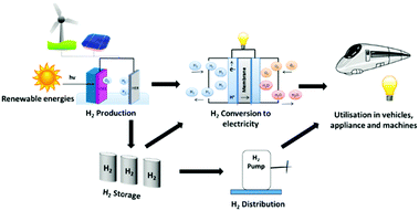
Hydrogen has been described as the ultimate clean energy source.11 Molecular hydrogen not only possesses a higher gravimetric energy density when compared with traditional fossil fuels, but can also be utilised to develop clean energy devices for the generation of electricity for national grids around the world. This concept is basis on the so-called hydrogen economy idea, which consists of the production of molecular hydrogen from renewable resources, its storage for later usage, distribution to local fuel cell sites, and utilisation in a fuel cell in order to generate electricity, Fig. 1.12–14
In the last five years electrochemical water splitting has become a technology of continuously increasing interest to the wider scientific community in a bid for the search for renewable fuels to replace the worlds’ ever dwindling fossil fuel reserves. Water electrolysis splits water into hydrogen at the cathode and oxygen at the anode, denoted as the Hydrogen Evolution Reaction (HER) and the Oxygen Evolution Reaction (OER), respectively.15–17 This process usually takes place in either acidic or alkaline media, as ionic species are needed to be present for the reaction to proceed. The overall reaction and the reactions which proceed in both media can be represented as follows:18
| 2H2O + energy → 2H2 + O2 | (1) |
| 4OH− → O2 + 2H2O + 4e− (Anode) | (2) |
| 4H2O + 4e− → 2H2 + 4OH− (Cathode) | (3) |
| 2H2O → O2 + 4H+ + 4e− (Anode) | (4) |
| 4H+ + 4e− → 2H2 (Cathode) | (5) |
| E(i) = E0 + ηa + |ηc| + iR | (6) |
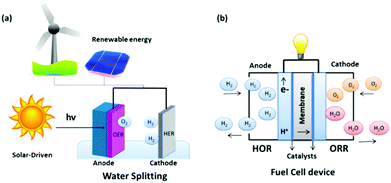
The energy required to drive this reaction can be generated from two routes; combining renewable energy technologies, such as wind, hydro or solar stations, with electrolyzer arrays, or incorporating appropriate semi-conductor materials (e.g. Fe3O4 or TiO2) with an active electrocatalyst as the working electrode in the electrolyzer and directly shining sunlight onto the electrode of interest, Fig. 2(a). The overall process of water splitting is hindered by the reaction on the anode, the OER, due to the large thermodynamic overpotential associated with this half reaction when compared to the cathodic reaction, the HER.23 Thus, for the overall water electrolysis process to become more efficient, significant advances must be continuously made in the field which mainly focus on discovering cheap, active catalysts to replace the current commercial standards for the OER in an electrolyser device.23 Additionally, research into the HER must still be on-going in parallel with the OER as any decrease in the overpotential for either reaction will result in a significant lowering of the cost of the process that will bring us one step closer to a hydrogen economy.24–27
Currently, the most efficient catalysts utilised commercially for the OER are based on the expensive and rare elements from the Platinum Group Metals (PGMs). In both acidic and basic media, RuO2 and IrO2 are considered the state-of-the-art materials for the OER reaction.28–31 However, the high cost of these materials compared to other metals combined with their lack of abundance renders their widespread use in commercial devices uneconomical.32,33 One should also note, another alternative way to potentially increase the efficiency of the HER is to couple this reaction with a thermodynamically more favourable reaction such as the Urea Oxidation Reaction (UOR).34–36 The UOR has a thermodynamic overpotential of 0.37 V which is approximately 0.9 V lower than the OER.34 However the UOR also suffers from high overpotential values (ca. 1 V) which places most of the UOR catalysts in literature near to the same activity of the OER catalysts on the RHE scale. For example, Yu et al., recently reported that a cheap TMO based catalyst exhibited a potential of 1.38 V vs. RHE at 10 mA cm−2 for the UOR.34 Alternatively, Zhang and co-workers recently reported that a low cost FeCoW evolved O2 at a current density of 10 mA cm−2 utilising a potential of 1.42 V vs. RHE.37 The catalysts reported in the two aforementioned studies, for the UOR and OER, are among the best catalysts in literature for their respective reactions. Hence, research into the generation of H2 by water electrolysis and other routes using a sacrificial reagent, e.g. urea, glucose etc., needs to be undertaken concurrently by the scientific community.34,38
Another extremely important reaction that suffers from inefficiency involved in the hydrogen economy idea is the Oxygen Reduction Reaction (ORR) which is a critical half-cell reaction in a H2/O2 fuel cell.39,40 This technology promises a clean energy conversion device utilised in-conjunction with an electrolyser to deliver electricity to the masses, Fig. 2(b). At a basic level, a fuel cell consists of an anode plate, a cathode plate and a proton selective membrane i.e. Nafion. In a H2/O2 fuel cell, H2 is delivered to the anode where the Hydrogen Oxidation Reaction (HOR) takes place, while the ORR takes place at the cathode plate. The overall reaction that takes place in a fuel cell and the reactions which proceed in both acidic and basic media for the HOR and ORR can be represented as follows:41–43
| 2H2 + O2 → 2H2O + energy | (7) |
| 2H2 + 4OH− → 4H2O + 4e− (Anode) | (8) |
| O2 + 2H2O + 4e− → 4OH− (Cathode) | (9) |
| H2 → 2H+ + 2e− (Anode) | (10) |
| O2 + 4H+ + 4e− → 2H2O (Cathode) | (11) |
Layered transition metal oxides and hydroxides
TMOs are composed of a transition metal from the d-block of the periodic table with oxygen. TMOs have many advantages including the ability to change their bonding structure, and hence their oxidation states, as a function of applied annealing temperature during material fabrication or applied electrochemical potential in situ; which allows for the evaluation of the OER and ORR of the same material.61 Of particular interest to various energy applications, such as OER and ORR, are layered TMOs. Layered TMOs consist of stacked quasi-2D sheets weakly held together by van deer's Walls interactions with strong in-plane covalent bonds. These structural properties allow for these materials to be easily exfoliated into their individual quasi-2D structures by various techniques.62–65Additionally, 2D or few-layer TMO based materials can also be achieved by manipulating/treating Layered Double Hydroxide (LDH). These materials consist of brucite-like layers, consisting of MO6 octahedral sites, which are positively charged. The overall net charge of these structures are achieved by anions or solvation molecules intercalated in between the layers.66,67 The most common LDH materials consist of two metal centers for the MO6 sites and the chemical formula for these materials are:68
| [M1−x2+M3+x(OH)2][An−]x/n·zH2O | (12) |
| [M(OH)2] | (13) |
Regardless of the class of the layered material, the 2D form of these layered TMOs often possess enhanced electrochemical properties compared to their bulk counterpart.70 The fabrication or synthesis of these layered catalysts spans a multitude of various routes including solvothermal,71 hydrothermal,72 microwave-assisted,73 thermal decomposition,74 low temperature synthesis,75 and precipitation methods.70 Then, other treatment processes including anion exchange and exfoliating processes, including chemical, mechanical and physical, are undertaken on these layered materials to enhance its electronic and chemical properties.76 A table of common layered TMO based materials, the synthetic route to produce the layered materials along with their exfoliated counterpart or anion exchange procedure, if applicable, found in literature that are utilised as catalysts in electrochemical energy applications are illustrated in Table 1.
| Layered TMO | Fabrication routes | Notes | Ref. |
|---|---|---|---|
| MnO2 | Room temperature wet chemistry (precipitation) and liquid phase exfoliation | MnO2 nanosheets: Mn(NO3)2·H2O + DI-water + PEG–PPG–PEG mixed together and heated. A KMnO4 solution added dropwise until brown precipitate formed. | 70 |
| Exfoliation: in IPA using sonic bath and centrifugation. | |||
| MnO2 | Thermal decomposition and sulfurisation process | Thermal decomposition: graphene oxide + KMnO4 mixed in water at 80 °C for 24 hours. Then filtered, washed and dried. | 74 |
| Sulfurisation process: MnO2 mixed with sulphur powder in a alumina crucible and calcined in a tube furnace for 12 hours under N2 flow. The temp was then raised to 250 °C and heated for an hour under N2 to evaporate the excess S. | |||
| MnO2 | Thermal decomposition | Thermal decomposition: KMnO4 heated at 500 °C for 5 hours. Then washed with DI water and dried at 80 °C overnight. | 77 |
| Ni(OH)2 | Liquid phase exfoliation of commercial powder | Exfoliation: carried out in sodium cholate in both water and N-methyl-pyrrolidone in a metal beaker using an ultrasonic tip. Then centrifugation to select nanosheet size. | 78 |
| Ni(OH)2 | Hydrothermal synthesis | Hydrothermal: nickel nitrate, Oleylamine and water were stirred for 30 min and transferred to an autoclave. The reaction vessel was annealed at 180 °C for 15 hours. | 54 |
| Co(OH)2 | Liquid phase exfoliation of commercial powder | Exfoliation: carried out in sodium cholate/isopropyl alcohol in a metal beaker using an ultrasonic tip for 4 h. Then centrifugation to select nanosheet size. | 79 |
| Co–Co LDH and Ni–Co LDH | Topochemical synthesis and anion exchange. | Topochemical synthesis: Ni and/or Co chloride salt + hexamethylenetetramine refluxed for 5 hours at 90 °C to produce the hydroxide. To fabricate the LDH*, the hydroxide + Br2 + acetonitrile was magnetically stirred for 1 and 5 days for the Co–Co LDH and the Ni–Co LDH, respectively. | 67 |
| Anion exchange: ethanol assisted anion exchange using sodium nitrate (NO3− ions). | |||
| Ni–Fe LDH | Hydrothermal synthesis and anion exchange. | Hydrothermal synthesis: nickel and iron nitrate salts mixed with urea + triethanolamine + water and transferred to a stainless steel Teflon cup and heated for 2 days at 150 °C. | 67 |
| Anion exchange: ethanol assisted anion exchange using sodium chloride (Cl− ions). | |||
| Ni–Fe LDH | Co-Precipitation and chemical exfoliation | Co-Precipitation: a NaOH/Na2CO3 solution was added dropwise to Ni and Fe nitrate salts. The suspension was stirred for 10 min and then heated to 65 °C for 24 hours. | 80 |
| Exfoliation: Ni/Fe oxide dispersed in formamide and stirred under N2 atmosphere for 2 days. The solution was then centrifuged to remove un-exfoliated material. |
Structures, fabrication routes and basic properties of common layered transition metal oxide catalysts utilised in O2 electrocatalysis
Binary layered oxides of transition metals
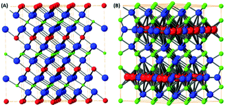
From the simple binary transition metal oxides, only a minority adopt a layered structure e.g. vanadium pentoxide, molybdenum trioxide and tungsten trioxide. The structure of layered transition metal oxides like vanadium(V) oxide, molybdenum(VI) oxide and hydrated tungsten(VI) oxide are shown on Fig. 3. These oxides are relatively volatile and large crystals can be prepared by a sublimation process under partially control oxygen pressure to avoid reduction of the materials.81,82 Exfoliation of these materials can be performed by mechanical methods; such as share force milling in appropriate solvents.83 In particularly, MoO3, and to a lesser extent the other binary transition metal layered oxides mentioned, are known to be catalytic for heterogeneous chemical reactions such as the ORR and OER.84 In literature, the catalytic activity of these materials can be related to the oxygen vacancies or possible formation of sub-oxides since these oxides tend to form various non-stoichiometric oxidic phases. These oxidic materials are typically synthesised on highly conductive material with large surface areas like graphene based materials. It has been shown, that the interaction of carbon based materials with these nanostructured oxides has resulted in synergic effects on the resulting catalytic properties.85The other group of binary layered oxides with a layered structure are based on transition metal oxide which were synthesised using suitable planar templates, for example TiO2.86,87 However, these materials have amorphous or non-layered crystallographic structure and exhibit highly anisotropic shape (platelet shape with single or few layers atoms thickness). The synthesis is typically based on self-assembling methods or by topochemical reactions (e.g. conversion of layered TiS2 into TiO2 sheets).86,87 The flexibility and variability of these methods allows for the synthesis of the most basic binary oxides.
Mixed transition metal layered oxides
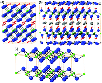
The mixed transition metal is formed with an alkali metal adopting layered structure. The most typical examples are LixCoO2 or KxMnO2 where the structure is based on hexagonally coordinated metal ions with oxygen and alkali metal atom layers. Due to the possibilities in the variation of alkali metal content these materials are highly popular for battery applications.88 The LixCoO2 structure is shown on Fig. 4(A). However, these materials don’t adopt true van der Waals layered structure therefore they can be exfoliated by chemical methods based on substitution/removal of alkali ions intercalated between the metal-oxide layers.89 The family of this type of layered oxides is very rich and from the ternary based systems KxMnO2, also called δ-MnO2 oxide or birnessite according its natural counterpart, is well known, Fig. 4(B). The other layered oxides in this family of materials can be based on iron, chromium, titanium and other transition metals.90 Transition metals form also several complex layered oxidic phases including titanates, tantalates, niobates, tungstates and its various mixed counterparts. Similarly, to birnessite type oxides, their exfoliation is based on the removal or substitution of alkali metals within layered structure. Their substitution with bulky ions, such as tetrabutylammonium ions, treatment with acids (hydrated protonic form) and subsequent reaction with tetrabutylammonium hydroxide significantly increase interlayer spacing and allows for their mechanical exfoliation to take place. These complex oxides exhibit several interesting physical properties including thermoelectric effects, ferroelectric and multiferroic properties, but to date their exploration as electrocatalysis for the OER and ORR has been very limited.Layered hydroxides, oxo-hydroxides and double layered hydroxides
The layered hydroxides are dominantly based on the brucite structural type, where the metal ion is hexagonally coordinated with six hydroxyls. Most of the M2+ transition metal sites adopt a hydroxide structure e.g. Fe(OH)2, Co(OH)2 and Cu(OH)2. The typical crystal structure of brucite type materials is shown in Fig. 5(C). Several of these hydroxides have limited stability issues with regard to pH, as well as their oxidation state. All of these brucite type oxides tend to dissolve at low pH and some at high pH values due to the formation of hydroxocomplex species e.g. [Zn(OH)4]2−. This problem can raise issues when investigating these materials for the OER and ORR as low/high pH solutions are utilised during experimental studies. The oxidation sensitivity is especially pronounced for Fe(OH)2 even when pyrophyric in its powdered dry state. The fabrication procedure is typically based on topochemical reactions which yield layered oxo-hydroxide materials.91,92Based on the layered hydroxide structure, there also exist a broad group of layered oxide-hydroxide of general formula MO(OH) which are generally formed by topochemical oxidation of layered hydroxides (e.g. lepidocrocite γ-FeO(OH)). The structure is shown on Fig. 5(A). The oxo-hydroxides are significantly more stable in comparison with metal hydroxides and can withstand relatively broad pH range, especially in alkaline environment.
An important group based on the brucite structure for the OER and ORR are the layered double hydroxides (LDH). The LDH structure consists of M2+ ions substituted with M3+ ions and in-between layers charge compensation anions, e.g. hydroxides, carbonates etc., are present. The structure of these materials are extremely varied; multiple possibilities for the anion and cation sites exist as well as the anion introduction into the interlayer space between hydroxide structures. The LDH structure can be observed in Fig. 5(B). The presence of multivalence ions results in a positive charge for the hydroxide layers compensated by lightly bonded anions. The general formula of LDH can be written as M1−x2+Mx3+(OH)2·Ax/nn−·mH2O where M2+ = Mg2+, Fe2+, Co2+, Ni2+, Zn2+ and others and M3+ = Al3+, Fe3+, Cr3+ and others. The synthesis is typically based on reaction of metallic ions at elevated pH (formed e.g. by thermal decomposition of urea under hydrothermal conditions). The presence of organic long chain anions like dodecylsulfate or lactate can form LDH with controlled and extremely high interlayer spacing. Such LDH with large interlayer spacing can be easily exfoliated by mechanical exfoliation like share force milling or ultra-sonication. Since the LDH can slowly dissolve at high pH (e.g. containing Al3+) or at lower pH, neutral solvents like water, alcohols or hydrocarbons are used. The presence of catalytically active transition metals, e.g. Mn, Fe, Ni and Co, in the LDH structure have made these materials an attractive option to study as OER and ORR catalysts throughout literature.
In recent years the amount of literature reported on the OER and ORR using layered TMOs has steadily increased however the impact may be over shadowed by the more popular Transition Metal Dichalcogenides (TMDs) for the HER. This review highlights and discusses recent research in the area of OER and ORR which utilise layered and 2D TMO materials as catalysts. With particular emphasis on how the fabrication route and additives/enhancement aids e.g. carbon nanotube as support for increased conductivity, can affect the performance of these important O2 reactions that are central to the implementation of a future hydrogen economy.
Oxygen evolution reaction (OER)
It is widely accepted that variations in the synthetic route and/or electrode fabrication technique can greatly affect the performance and stability of catalysts for electrochemical energy processes.93,94 Therefore, and more specifically, investigating appropriate pathways to produce and fixate layered TMO catalysts on suitable current collectors for the optimisation of the OER is a major area of research that is currently on-going.95 Moreover, further processing techniques and/or conductive aids have been reported to further enhance ‘bare’ layered TMOs for the OER.76 Multiple studies on layered TMO catalysts will be compared and discussed herein to evaluate and understand the optimum fabrication parameters in respect to their OER performance.Cheap layered TMOs, e.g. Ni(OH), Co(OH)2, MnO2 and NiFe based materials, from the first row of the transition metals (d-block) periodic table have received an increasing amount of interest as of late as catalysts for the OER. Liquid phase exfoliation (LPE) of Ni(OH)2 and Co(OH)2 layered materials has been reported to increase the activity of these materials for the OER compared to their layered stucture.76,78,79 For example, Ni(OH)2 exfoliated by LPE in a iso-propyl alcohol (IPA) dispersion was deposited onto Ni foam by a spraying technique and the OER performance was analysed in 1 M NaOH, Fig. 6(A).78 Before OER the exfoliated Ni(OH)2 was confirmed by X-ray Photoelectron Spectroscopy (XPS) measurements which revealed no change in the oxidation state of the Ni atoms. However, a broad peak in the O1s core level region was noted for the exfoliated nano-sheets when compared to the pre-treated Ni(OH)2. This broadening was attributed to the utilization of sodium cholate surfactant during the exfoliation process. The OER activity of exfoliated Ni(OH)2 on Ni foam out-performed the bare Ni foam by a factor of 2.5 with respect to current density, Fig. 6(C and D).78 The authors further enhanced the exfoliated Ni(OH)2/Ni foam electrode by electrochemically polarising the electrode at a current density of 10 mA cm−2 for a period of 100 hours; an SEM image of polarised electrode can be observed in Fig. 6(B). The authors suggested, in accordance with previous reports, that the increased performance of the polarised Ni(OH)2 electrode was a result of the conversion of the Ni(OH)2 phase to a more active NiOOH phase before the OER.96–98 However, since the OER experiments were conducted in NaOH with Fe impurities, it should be noted that this increase in the OER performance of the pre-polarised Ni(OH)2/Ni foam electrode may not be due to a more active NiOOH phase but the substitution of Ni ions by Fe impurity ions from the NaOH electrolyte solution in the Ni(OH)2 lattice. It has been extensively shown that Ni(OH)2 in KOH or NaOH electrolyte with Fe impurities performances as a better OER catalysts than in the same electrolyte with no Fe impurities.99,100 This substitution was first observed electrochemically by Corrigan et al. in the 1980s and more recently numerous groups using materials characterisation techniques i.e. XPS and Raman spectroscopy.99–102
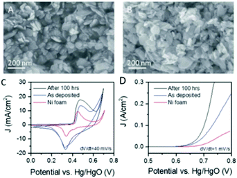 | ||
| Fig. 6 Liquid exfoliated Ni(OH)2 nanosheets. (A and B) SEM images of an as-prepared Ni(OH)2 film and (B) a film after activation by 100 h polarisation with current density of 10 mA cm−2. (C) Cyclic voltammograms measured for supercapacitor electrodes fabricated from Ni(OH)2 films on Ni foam current collectors before and after activation. A CV curve measured for the bare Ni foam is shown for comparison. (D) Polarisation curves for OER from Ni(OH)2 electrodes fabricated from Ni(OH)2 films on Ni foam current collectors before and after activation with the equivalent curve for the bare Ni foam shown for comparison. (Reproduced with permission (ref. 78) Copyright Royal Society of Chemistry (2016).) | ||
The same exfoliation process conducted on the layered Ni(OH)2 was applied also to Co(OH)2 which produced nano-sheets with the dimensions of 88 nm in length and 94 mm width, Fig. 7(A–E).76,79 After exfoliation, extensive material characterisation was carried out on the Co(OH)2 to reveal that, unlike the exfoliated Ni(OH)2, XPS showed a slight change in the chemical environment for the Co(OH)2 exfoliated materials, Fig. 7(G and H). However, similarly to the Ni(OH)2, a broad peak in the O1s region is observed which, again, may be due to the sodium cholate used during the liquid phase exfoliation process.76,78
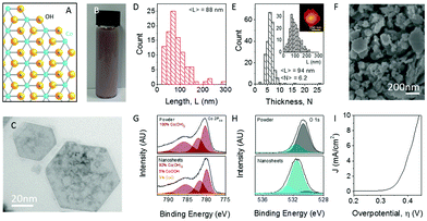 | ||
| Fig. 7 Exfoliation of Co(OH)2 into nanosheets. (A) Structure of cobalt hydroxide, Co(OH)2. Blue, Co; yellow, O; silver, H. (B) Photograph of typical Co(OH)2 dispersion in surfactant solution (concentration of Co(OH)2 was 7 mg mL−1). (C) Representative low-resolution TEM image of exfoliated Co(OH)2 nanosheets. (D) Nanosheet length distribution as measured by TEM. (E) Nanosheet thickness (layer number) distributions as measured by AFM with length distribution and sample image shown in the inset. (F) SEM image of a vacuum filtered film of Co(OH)2 nanosheets. (G) Co 2p3/2 XPS spectra of Co(OH)2 pretreated bulk powder (top) and a film of re-aggregated nanosheets (bottom). (H) O 1s core-level spectra of pretreated powder (top) and film of re-aggregated nanosheets (bottom). (I) Polarization curve for an electrode consisting of vacuum filtered Co(OH)2 nanosheets on a glassy carbon electrode (1 M NaOH, scan rate 1 mV s−1). (Reproduced with permission (ref. 76) Copyright Wiley and Sons (2018).) | ||
This exfoliated Co(OH)2 was vacuum filtrated onto a GC disk electrode, Fig. 7(F) and measured for its OER performance. As noted by the authors the OER performance of the exfoliated Co(OH)2 was poor. In order to enhance the OER activity of this material, carbon nanotubes (CNTs) in various weight percentages (1–10%) were added to the exfoliated Co(OH)2 dispersion and, again, vacuum filtrated onto GC electrodes, Fig. 8(A). As observed in Fig. 8(B and C), the overpotential at 10 mA cm−2 decreases while the current density increase, respectively, with additional CNT weight content to 5% and then levels off. This study indicates there is a maximum amount of CNT content needed to be added to the Co(OH)2 before no more enhancing effects are observed. Unfortunately, according to other reports, CNTs, and to a larger extent multi-walled CNT, can also catalyse the OER, therefore it is not clear if the CNT simply improves the conductivity of the Co(OH)2 network, or whether the CNTs themselves participate in catalysis of the OER.103
 | ||
| Fig. 8 Co(OH)2–SWNT composite OER catalysts. (A) Linear sweep voltammograms for composite electrodes with a fixed Co(OH)2 loading of 0.9 mg cm−2 for a range of nanotube contents. (B) Overpotential required to produce 10 mA cm−2 and (C) current density at overpotential of 0.3 V, both plotted as a function of SWNT volume fraction. All figures pertain to s-Co(OH)2 using 1 M NaOH as an electrolyte where applicable. (Reproduced with permission (ref. 76) Copyright Wiley and Sons (2018).) | ||
In a subsequent report by the same group, the exfoliated Co(OH)2 was deposited onto two different types of high area supports; glassy carbon (GC) foam and nickel (Ni) foam.79 The results reveal the exfoliated Co(OH)2 on the Ni foam was a superior electrode when compared to the same material on the GC foam in terms of absolute OER overpotetnial i.e. the overpotential at 10 mA cm−2. This value was 280 and 380 mV for the Co(OH)2 on the Ni and GC foams, respectively, in 1 M NaOH. However, when comparing the activity of the Co(OH)2 catalysts/substrate combination to the bare support in relative terms the Co(OH)2 on the GC support was the more appropriate relationship. The Co(OH)2 on the GC had an improved OER performance by 57% compared to the bare GC, while the Co(OH)2/Ni achieved a 30% increase over the bare Ni support.79 Interestingly, the Co(OH)2 on the Ni foam behaved as a better OER electrocatalyst when compared to the exfoliated Ni(OH)2 on the same Ni foam support previously discussed in this review by the same group.78 However, regardless of the actual OER performance values, it is clear that the nature of the support plays a role in the activity of layered TMO material.
In nature, Photosystem II is a molecular complex that is utilised to produce molecular O2 in plants and algae. This complex is based around a Mn and Ca center. For this reason, bulk Mn-based TMO materials (MnO, Mn2O3, Mn3O4 and MnO2) have been extensively studied in literature.57,61,105–107 However, the OER overpotentials reported for these materials have not yet reached that of the state of the art.15,16 Recently, few layer/2D δ-MnO2, also known as birnessite, has emerged as a potential candidate for water splitting. Birnessite occurs naturally and is composed of 2D layers consisting of O ions octahedrally coordinated to a central Mn ion with both Mn3+ and Mn4+ present. The overall net charge is negative, however charge neutrality is usually governed by the positive charged alkali metal ions (e.g. K+, Na+) between the 2D layers. The promise of this layered/2D-layer spans multiple reasons including (1) optimum OER active sites for Mn have been postulated to lie between Mn3+ and Mn4+ and (2) there has been an indication of increased conductivity and electronic properties for few layer/2D birnessite compared to bulk MnO2.57,104,108,109
2D δ-MnO2 on Ni foam produced by an in situ hydrothermal synthesis using KMnO4 and H2O was investigated for its OER characteristics in 0.1 M KOH, Fig. 9.104 The OER measurements of the 2D δ-MnO2 and bulk MnO2 on Ni foam (not in figure) showed that the 2D δ-MnO2 was a much superior catalyst; the overpotential at 10 mA cm−2 for the 2D MnO2 was 0.32 V for the exfoliated material while the bulk MnO2 did not reach this current density at all to allow for the authors to report an overpotential. Interestingly, the 2D δ-MnO2 material even proved to be better than the OER state of the art OER catalysts, IrO2, in regards to the overpotetnial at 10 mA cm−2 and Tafel slope values, see Fig. 9(A) and (B). The enhanced performance of the 2D δ-MnO2 was rationalised to be due to the larger electrochemical surface area determined for the 2D material over the bulk; 19.58 and 0.80 mF cm−2 respectively, which could be rationalised due to the larger surface area of the 2D nanosheets. Another reason for the increase in the OER activity could be due to the lower oxidation state (Mn3+), revealed by the XANES measurement, that is only observed in the 2D structure of MnO2 and gives rise to a half-metallic state not observed in bulk MnO2.
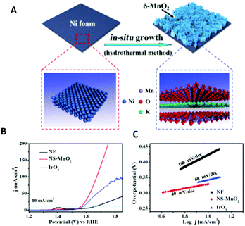 | ||
| Fig. 9 Schematic showing the in situ growth of ultrathin δ-MnO2 nanosheets on an Ni foam (NS-MnO2). (A) Linear sweep voltammetry (LSV) curves for OER at a scan rate of 5 mV s−1. (B) Tafel plots for OER. (C) LSV curves for HER at 5 mV s−1. (Reproduced with permission (ref. 104) Copyright Wiley and Sons (2017).) | ||
Increasing the interlayer spacing of layered MnO2 utilising transition metal ions e.g. Ni2+, can also affect its OER catalytic abilities.110 As demonstrated previously the OER activity of this layered material can be tuned by intercalating various amount of Ni2+ ions (6.1, 6.5 and 7.7%) into the spacings between the 2D layers by a wet chemical ion exchange reaction during synthesis. This resulted in a decrease in the interlayer spacing with increasing Ni2+ %; the interlayer spacings for the 6.1, 6.5 and 7.7% Ni intercalated layered MnO2 was 7.17, 7.06 and 7.04 Å, respectively. The interlayer spacing for birnessite is typically 7.27 Å.110
The OER activity for the layered and intercalated Ni2+ MnO2 was determined in 1 M KOH, see Fig. 10. A noticeable increase in performance for the Ni2+ layered MnO2 over the bare material can be observed. The data shows that with decreasing interlayer spacing, the OER results become more cathodic with the 7.7% Ni2+ MnO2 catalyst exhibiting an overpotetnial at 10 mA cm−2 of 400 mV.110 This is a significant increase in activity when compared to the bare MnO2 as a 350 mV difference is observed. This synthetic route should be exploited using other OER catalysts as inserting other transition metal ions, e.g. Ni2+, into the interlayer spaces of layered TMOs may be way of promoting the activity of these materials. Anion exchange is already utilised in research for enhancing electrocatalytic performance of layered TMOs, but the anions used are not currently based on other transition metals, e.g. Ni2+, that are known to be active for the OER.54
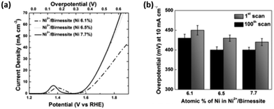 | ||
| Fig. 10 (a) Polarization curves for Ni2+/birnessite with varying amounts of Ni. (b) Comparison of overpotentials to reach 10 mA cm−2 for Ni2+/birnessite with increasing electrochemical cycles. (Adapted with permission (ref. 110) Copyright Wiley and Sons (2016).) | ||
The majority of layered TMO materials which undergo anion exchange consist of more than one metal therefore this section of the review will focus on bi- and tri-metal TMOs. Recently, in a research setting, NiFe based hydroxides/oxides have emerged as a cheap alternative for the OER in alkaline media compared to PGM based oxides i.e. RuO2 and IrO2. These materials also exhibit a layered structure, with some research groups having exploited this by changing the interlayer spacings of the NiFe by anion exchange.
For example, layered Ni0.8Fe0.2OH LDH prepared by a hydrothermal synthesis was subjected to anion exchange, using BO33− ions, resulted in an increased in the interlayer spacing from 5.4 Å to 6.2 Å.111 The anion exchange process introduced a boost in the LDH specific surface area from 150.9 m2 g−1 to 170.9 m2 g−1 which was determine by BET analysis. Additionally the OER properties of the layered Ni0.8Fe0.2OH LDH in 1 M KOH were clearly enhanced after anion exchange as the overpotential at 10 mA cm−2 and the Tafel slope values both improved. The overpotetnial and Tafel slope value increase by ca. 50 mV and 25 mV, respectively, for the BO33− treated material compared to the bare LDH. This enhancement in the OER catalytic activity of the layered Ni0.8Fe0.2OH LDH was correlated with the increase in the interlayer spacing exposing more active sites due to the anion exchange process. In this study, it was suggested that the O2 mechanism of the borate intercalated LDH was enhanced compared to the bare LDH due to the borate ions acting as a proton accepting agent which increases the O–O bond formation during the OER.111
Another recent study on the OER properties of an anodic borate doped Ni(OH)2 has also indicated that the presence of borate enhances the proton accepting properties during the OER compared to a non-doped Ni(OH)2 catalyst, Fig. 11(A and B).112 The overpotential of the borate doped Ni catalyst is increased at 10 mA cm−2 compared to the non-doped Ni material. However, as the Tafel slope values are similar the mechanism in which the OER proceeds is assumed to be the same; the rate determining step involves the formation of adsorbed peroxide intermediates (–OOH). Therefore, the enhancement in the OER was attributed to the reversible transformation of the BO33− to a BO33-OH. The presence of the four coordinated borate was confirmed by NMR spectroscopy. This BO33-OH can accept a proton from the Ni–O–OH2 intermediate and subsequently release H2O, and an electron, leaving a Ni-OOH site.112 This step may require less energy to proceed compared to the equivalent step during the O2 generation of the bare Ni(OH)2, Fig. 11(C), resulting in the enhanced activity, Fig. 11(D).
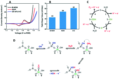 | ||
| Fig. 11 (A) iR-corrected cyclic voltammograms of OER on B-NOH, NOH, and Ir/C (B) comparison of Tafel slopes (C) the PCET mechanism of OER in the literature. “S” represents a surface site and (D) the proposed rate determining step (RDS) on a borate-coordinated Ni active center. (Adapted with permission (ref. 112) Copyright American Chemical Society (2018).) | ||
By comparing recent studies, it has been further shown that the absolute OER overpotentials of NiFe LDH based catalysts fluctuate depending on the ions utilised during the anion exchange process.113 Similarly to the previous study on intercalated NiFe with BO33− ions, the OER performance of a NiFe LDH intercalated with Mo ions during anion exchange, also exhibited a more cathodic behavior favoring the OER.111 For this particular study, the OER optimisation as a result of the anion exchange process was clear as the overpotential at 10 mA cm−2 for the NiFe Mo treated LDH increased by 35 mV compared to the untreated NiFe LDH. The authors attributed this observation to an increase in the electrochemical active sites as a result of the ultrathin thickness of the anion exchanged NiFe LDH.
More interestingly when comparing the two aforementioned studies, the choice of ion for the anion exchange process is evidently important in terms of the resulting electrochemistry. The two previous works use different layer intercalating anions, e.g. Mo or BO33− ions, in the anion exchange process but a similar hydrothermal synthetic route to make the NiFe LDHs. Therefore it can be noted that the OER activity changes depending on the ion utilised. The OER overpotentials for the BO33− ion intercalated NiFe LDH exhibited a larger increase when compared to the Mo ions; a difference of 50 mV was observed for the borate intercalated material and only 35 mV for the Mo intercalated material when compared to their relevant untreated counterpart. Perhaps indicting the BO33− ions may be a more suitable choice of anion over Mo ions for the anion exchange process for NiFe based materials.
Furthermore, the OER activity of the NiFe LDH can be readily tuned by adopting different phosphorus based anions; phosphate, phosphite and hypophosphite, during the anion exchange process of an carbonate intercalated NiFe LDHs.114 The OER performance of the NiFe LDH reveals that the choice of intercalation anion has an effect on the electrocatalytic performance, Fig. 12(a–c). From the LSV curves, Fig. 12(a), it is evident that the phosphorous based anions significantly improves the OER when compared to the carbonate intercalated NiFe LDH, however the Tafel slope was not affected; indicating that O2 evolution proceeds by the same mechanism for all of the NiFe LDH, Fig. 12(b). Interestingly, the electrochemical surface area (ECSA), Fig. 12(c), exhibited the same trend to the overpotential values at 10 mA cm−2i.e. the hypophosphite NiFe showed the best OER overpotentials and the highest ECSA, followed by the phosphite NiFe, then the phosphate NiFe and, finally, the carbonate NiFe.
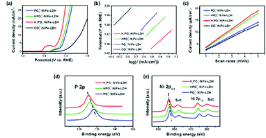 | ||
| Fig. 12 (a) Polarisation curves of four LDH catalysts (PO43−/NiFe-LDH, HPO32−/NiFe-LDH, H2PO2−/NiFe-LDH, and CO32−/NiFe-LDH); H2PO2−/NiFe-LDH shows the lowest onset potential and fastest current density increase; (b) Tafel plots, (c) Cdl calculations for the four catalysts. XPS data of the PO43−/NiFe-LDH, HPO32−/NiFe-LDH, and H2PO2−/NiFe-LDH: (d) P 2p and (e) Ni 2p spectra. (Adapted with permission (ref. 114) Copyright Springer (2017).) | ||
The rationale for the trend observed for the NiFe LDH based phosphorus catalysts originates from a previous observation that the OER activity of NiFe based catalysts is strongly influenced by the Ni sites.115 From XPS analysis, Fig. 12(d and e), it is clear the lowest Ni valence states are present for the NiFe/hypophosphite and can be correlated to this anion (H2PO2−) possessing the strongest reducibility compared to the other anions. Hence, more electron rich Ni sites would be available for oxidation during the OER i.e. more active sites.
Additionally, the H2PO2− NiFe possess the largest ECSA/double layer capacitance value of 3.8 μF cm−2 when compared to 3.2 and 3.6 μF cm−2 for the PO43− and the HPO32− NiFe based LDH, respectively. This is an interesting example of when the OER activity of a material (NiFe LDH) can be tuned for the OER by using various anions in the synthetic process.
In the literature, it has been shown that a combination of both anion exchange and liquid phase exfoliation can improve the oxygen evolution properties of various bi-metallic LDH materials such as CoCo, NiCo and NiFe LDHs when compared to its bulk LDH and to the state-of-the-art IrO2 for OER.67 Unlike other studies previously mentioned in this review, this work utilised anion exchange as a pre-conditioning step before the exfoliation of the 2D materials by liquid phase exfoliation, rather than the main treatment step. The anion exchange process facilitates the delamination of the 2D structures during the exfoliation process as the interlayer spacings were increased prior to exfoliation.
The anion exchange process was carried on the topochemical fabricated CoCo and NiCo LDH by exchanging the Br− ions with NO3− ions and for the hydrothermally produced NiFe by switching the CO3− ions with ClO4− ions which was successful tracked by XRD Fig. 13(a) and imaged by TEM-EDX, Fig. 13(b–e). The interlayer spacing of the CoCo and NiCo increase from 7.8 Å to 8.7 Å, while the initial interlayer spacing of the NiFe LDH increased from 7.7 Å to 9.1 Å. Subsequently, the chemical composition and morphology of the initial LDHs were maintained. Liquid phase exfoliation was subsequently carried out on the LDH to form 2D structures and was confirmed by a combination of using the Tyndall effect to prove the colloidal nature of the exfoliated suspension, the determination of the 2D layers by TEM analysis, and the absence of the diffraction peaks in the XRD analysis, Fig. 13(a), when compared to the bulk LDHs.
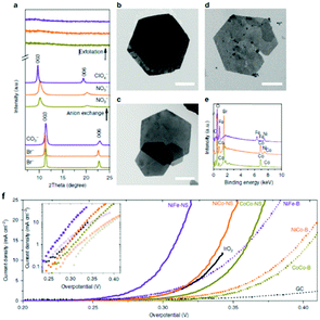 | ||
| Fig. 13 (a) XRD spectra. (b–d) TEM images of (b) CoCo LDH–Br. Scale bar, 1 mm. (c) NiCo LDH–Br. Scale bar, 1 mm. (d) NiFe LDH–CO32−. Scale bar, 150 nm. (e) Energy-dispersive X-ray spectra. CoCo LDH: yellow-green lines; NiCo LDH: orange lines; NiFe LDH: purple lines. (f) Polarization curves. Inset shows the Tafel plots. Scan rate was 5 mV s−1. The loading was about 0.07 mg cm−2 for LDH materials and 0.21 mg cm−2 for IrO2 nanoparticles. (Reproduced with permission (ref. 67) Copyright Nature Publishing Group (2014).) | ||
The OER performance of the bulk and exfoliated LDHs were determined in 1 M KOH and subjected to the same experimental conditions and can be seen in Fig. 13(f). The results show that all of the exfoliated LDH was significantly enhanced when compared to their bulk counterpart in respect to the measured overpotetnial at a current density of 10 mA cm−2. The NiCo and NiFe also out-performed IrO2; a state-of-the-art OER catalyst.
The authors attribute the dramatic difference in activity to a greater exposure of the MO6 sites after exfoliation, see Fig. 13. It is evident, that these MO6 sites are the active site for OER in these LDH materials therefore a greater number of these sites will be readily accessible during water oxidation when compared to the bulk LDH, where a portion of these MO6 sites will be blocked by the charge neutralising anion between the 2D layers (Fig. 14). Furthermore, it is quite clear that this increase in activity is due to the rise in active site density and not due to a change in the ECSA as the increase in the ECSA 2D materials is not sufficient to explain the improvement seen in the OER performance.
 | ||
| Fig. 14 Schematic representation of materials’ structures. (a) Layered hydroxides. d1 is the inter-layer distance of the hydroxide. (b) LDHs with inter-layer anions and water molecules. d2 is the inter-layer distance of the LDHs. (c) Exfoliated LDH monolayers dispersed in a colloidal solution. Each single layer is composed of edge-sharing octahedral MO6 moieties (M denotes a metal element). Metal atoms: purple spheres; oxygen atoms: red spheres; inter-layer anions and water molecules: grey spheres. Hydrogen atoms are omitted. (Reproduced with permission (ref. 67) Copyright Nature Publishing Group (2014).) | ||
Selecting the appropriate trivalent ion during the synthetic procedure for a LDH is essential to improve the performance of the catalyst for OER. Recently, multiple studies have emerged that highlights the advantage of fabricating LDH with Fe3+ as the trivalent species over Al3+ ions for the OER.116,117 One particular study, that co-precipitates various CoFe and CoAl LDHs with different percentages of a Fe trivalent ion from 15 to 45% in relation to the divalent ions, reports that not only does increasing the amounts of Fe enhance, to 35%, the CoFe LDH towards the OER but the addition of subsequent amounts of Al to the Co for the CoAl LDH suppresses the OER activity, Fig. 15.117 The reason for the enhancement for the CoFe with increase amounts of Fe3+ is not pin-pointed by the authors experimentally but is rationalised by theories expressed by other groups, which suggests the Fe3+ is the active site for the OER and the Co2+ is acting as a host material.118 Furthermore, the authors proposed the OER mechanism on the CoFe LDH proceeds at lower potentials compared to a Co only material due to substitution of the Co sites with Fe sites. This is based on a previously reported Co OER mechanism which states that at high OER potentials the Co4+ ion, bonded to oxo groups, is a vital intermediate for active Co OER catalysts.119 The Co4+ promotes the proton coupled electron transfer (PCET) step resulting in the formation of the O radicals on the Co3+ sites before the rate determining step and the generation of O2. However, in the case of the CoFe LDH, when Fe ions is substituted for some of the Co sites, this PCET step takes place on Fe4+, as Fe is believed to be oxidised at lower potentials, enhancing the OER activity.117
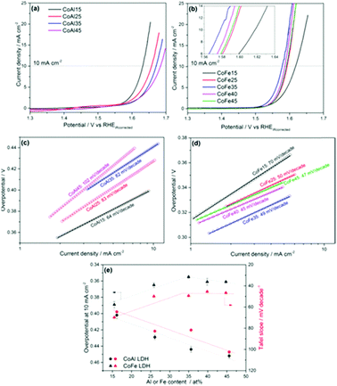 | ||
| Fig. 15 OER activities of the (a) CoAl and (b) CoFe samples; Tafel slopes of the (c) CoAl and (d) CoFe samples; (e) overpotential at 10 mA cm−2 and Tafel slopes of the catalysts versus Al/Fe atomic content, as determined by ICP-OES. (Reproduced with permission (ref. 117) Copyright Wiley and Sons (2017).) | ||
Finding the true reason for the enhanced catalytic effect of LDH materials when Fe3+ is utilised as the trivalent ion could lead to better and more active OER catalysts as the fabrication of LDH materials could be specifically designed to mimic these findings.
This study and all of the previously highlighted reports in this review, summarised in Table 2, show that the fabrication of LDH from the choice of trivalent ions to the treatments (anion exchange or exfoliation to 2D phase) applied after synthesis are critical to the performance of these materials as OER catalysts. It is evident that aforementioned treatments greatly improve the OER properties of the ‘bare’ LDH and more studies into these fabrication methods will undoubtedly see a further increase over the next number of years. These advances could provide an avenue to discover a cheap and active catalyst based on an LDH materials for electrolysis. This would greatly benefit the current energy crisis in finding an alternative energy conversion catalyst as an alternative to fossil fuels.
| Material | Intrinsic properties related to increase in OER activity as reported in the relevant study | Structure of catalysts | OER overpotential (V) at 10 mA cm−2 | Ref. |
|---|---|---|---|---|
| Ni(OH)2 | The authors suggest that the Ni(OH)2 which was electrochemically activated has been converted into the more OER active NiOOH phase. | 2D | ca. 0.38 | 78 |
| Ni(OH)2 electrochemically activated | 2D | ca. 0.35 | 78 | |
| Co(OH)2 | The smallest Co(OH)2 NS exhibited the best OER activity due to their high edge content compared with the bulk Co(OH)2 and the larger Co(OH)2 NS. | Brucite | 0.45 | 76 |
| The electrically and mechanical properties of the catalyst was enhanced by adding CNT which increased the OER activity of the Co(OH)2 NS materials. | ||||
| Co(OH)2 NS | 2D | 0.33 | 76 | |
| Co(OH)2 NS with 10 wt% CNT | 2D | 0.29 | 76 | |
| δ-MnO2 | The increase in the OER performance of the exfoliated δ-MnO2 was rationalised by the increase in the electrochemical surface area. | Birnessite | Did not reach 10 mA cm−2 | 104 |
| δ-MnO2 exfoliated | Birnessite | 0.32 | 104 | |
| Bare MnO2 | The authors suggests that the increasing presence of Ni(OH)2 increases the OER activity due to the tighter confinement of the Ni(OH2) in the birnessite interlayers which increases the orientation of the water molecules, promoting the OER. | Birnessite | 0.75 | 110 |
| MnO2 with 6.1% Ni | Birnessite | 0.43 | 110 | |
| MnO2 with 6.5% Ni | Birnessite | 0.40 | 110 | |
| MnO2 with 7.7% Ni | Birnessite | 0.40 | 110 | |
| Ni0.8Fe0.2OH | The increase in the activity of the NiFe based LDH intercalated with borate was attributed to the increase in the specific surface area which in turn increased the mass transport and charge transfer properties compared to the NiFe which was not intercalated with borate ions. | Hydrotalcite | 0.35 | 111 |
| Ni0.8Fe0.2OH intercalated with BO33− | Hydrotalcite | 0.27 | 111 | |
| Ni(OH)2 | The ECSA measurements of the bare and doped Ni(OH)2 revealed that the ECSA was the same. The authors concluded that the borate groups enhances the PCET. | Brucite | 0.37 | 112 |
| Ni(OH)2 doped with BO33− | Brucite | 0.32 | 112 | |
| NiFe LDH | The NiFe–Mo LDH exhibited a higher availability of electrochemical active sites which the authors correlated with the increase in the OER compared to the NiFe LDH. | Hydrotalcite | >0.28 | 113 |
| NiFe LDH intercalated with Mo ions | Hydrotalcite | 0.27 | 113 | |
| NiFe intercalated with PO43− | The lowering of the Ni valence state by the phosphorus based ions results in the increased availability of electron rich Ni sites for the OER. | Hydrotalcite | 0.27 | 114 |
| NiFe intercalated with HPO32− | Hydrotalcite | 0.25 | 114 | |
| NiFe intercalated with H2PO2− | Hydrotalcite | 0.23 | 114 | |
| NiFe intercalated with CO32− | Hydrotalcite | 0.35 | 114 | |
| CoCo bulk | The increase in OER activity from the bulk to the NS materials attributed to the increase in active site density and conductivity of the NS materials. | Hydrotalcite | 0.39 | 67 |
| NiCo-bulk | Hydrotalcite | 0.38 | 67 | |
| NiFe-bulk | Hydrotalcite | 0.35 | 67 | |
| CoCo NS | 2D | 0.35 | 67 | |
| NiCo NS | 2D | 0.33 | 67 | |
| NiFe NS | 2D | 0.30 | 67 | |
| CoAl 15 | The presence of Al ions in the LDH structure decreases activity. | Hydrotalcite | 0.40 | 117 |
| CoAl 25 | Hydrotalcite | 0.43 | 117 | |
| CoAl 35 | Hydrotalcite | 0.44 | 117 | |
| CoAl 45 | Hydrotalcite | 0.45 | 117 | |
| CoFe 15 | Substitution of Fe ions for the Co ions in the LDH structure which ultimately leads to a Fe4+ site facilitating the PCET to the Co3+ sites during the OER. | Hydrotalcite | 0.39 | 117 |
| CoFe 25 | Hydrotalcite | 0.37 | 117 | |
| CoFe 35 | Hydrotalcite | 0.36 | 117 | |
| CoFe 40 | Hydrotalcite | 0.37 | 117 | |
| CoFe 45 | Hydrotalcite | 0.365 | 117 |
Oxygen reduction reaction (ORR)
Recently, various reports on the ORR and the use of layered transition metal oxide catalysts have emerged. Similar to the OER, post-fabrication treatment of these layered TMO based materials can also show enhancements toward the ORR, see Table 3. For example MnO2 layered nanosheet materials exhibited improved ORR activity after a so called ‘sulfurisation process’. This MnO2 based nanosheet was prepared by adding KMnO4− into a solution of graphene oxide and water at 80 °C and mixed for 24 hours.74 The product was filtered, washed and dried, then subjected to the ‘sulfurisation process’. This entailed mixing sulfur powder with the layered MnO2 nanosheet product in a crucible and exposing the powder mixture to 155 °C to introduce nanosize pores into the MnO2 nanosheets, see Table 1 for more details and Fig. 16(a) for fabrication schematic.| Material | Intrinsic properties related to increase in ORR activity as reported in the relevant study | Structure of catalysts | ORR E1/2 potential (V) vs. RHE or trend in activity in relevant study | Ref. |
|---|---|---|---|---|
| MnO2 | Increase in oxygen vacancies. | Birnessite | 0.69 | 74 |
| Porous MnO2 | Birnessite | 0.73 | 74 | |
| NiFe LDH with graphene oxide (GO) | Increase in ORR sites due to strong interactions between the NiFe and the rGO compared to the NiFe and the GO. | Hydrotalcite | NiFe with the rGO outperformed the NiFe with GO. | 120 |
| NiFe LDH with reduced graphene oxide (rGO) | Hydrotalcite | 120 | ||
| NiFe on N-doped graphene-like 3D macro–meso-porous carbon | None suggested by authors. | Hydrotalcite | NiFe fabricated directly on the N-doped graphene-like carbon during fabrication outperformed the NiFe mixed with the carbon post fabrication. | 123 |
| NiFe mixed with NiFe N-doped graphene-like 3D macro–meso-porous carbon | Hydrotalcite | 123 | ||
CoNiFe (Co![[thin space (1/6-em)]](https://www.rsc.org/images/entities/char_2009.gif) : :![[thin space (1/6-em)]](https://www.rsc.org/images/entities/char_2009.gif) Ni = 67 Ni = 67![[thin space (1/6-em)]](https://www.rsc.org/images/entities/char_2009.gif) : :![[thin space (1/6-em)]](https://www.rsc.org/images/entities/char_2009.gif) 33) (M1) 33) (M1) |
The optimum ORR activity of the M3 catalysts was attributed to the increase in oxygen vacancies due to the higher amount of NiO and octahedral Co3+ sites in the spinal structure of the M3 material compared to the M1 and M2 catalysts. | Hydrotalcite | M3 > M1 > M2 | 124 |
CoNiFe (Co![[thin space (1/6-em)]](https://www.rsc.org/images/entities/char_2009.gif) : :![[thin space (1/6-em)]](https://www.rsc.org/images/entities/char_2009.gif) Ni = 73 Ni = 73![[thin space (1/6-em)]](https://www.rsc.org/images/entities/char_2009.gif) : :![[thin space (1/6-em)]](https://www.rsc.org/images/entities/char_2009.gif) 27) (M2) 27) (M2) |
Hydrotalcite | 124 | ||
CoNiFe (Co![[thin space (1/6-em)]](https://www.rsc.org/images/entities/char_2009.gif) : :![[thin space (1/6-em)]](https://www.rsc.org/images/entities/char_2009.gif) Ni = 57 Ni = 57![[thin space (1/6-em)]](https://www.rsc.org/images/entities/char_2009.gif) : :![[thin space (1/6-em)]](https://www.rsc.org/images/entities/char_2009.gif) 43) (M3) 43) (M3) |
Hydrotalcite | 124 | ||
| PPy/rGO | The authors reported synergistic effects for the enhanced ORR activity of the CoNiMn–PPy/rGO catalyst. | n/a | CoNiMn–PPy/rGO > CoNiMn–rGO > PPy/rGO | 125 |
| CoNiMn–rGO | Hydrotalcite | 125 | ||
| CoNiMn–PPy/rGO | Hydrotalcite | 125 |
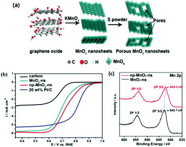 | ||
| Fig. 16 (a) Schematic diagram for the synthesis of np-MnO2-ns and (b) ORR performance of carbon, MnO2-ns, np-MnO2-ns, and 20 wt% Pt/C in O2-saturated 0.1 M KOH aqueous solution at room temperature, LSV measured at 5 mV s−1 and 1600 rpm and (c) XPS curves for the MnO2-ns and np-MnO2-ns materials. (Reproduced with permission (ref. 74) Copyright Wiley and Sons (2018).) | ||
The ORR performance, Fig. 16(b), reveals that the post-fabrication sulfurisation process improved its catalytic activity; E1/2vs. RHE by 40 mV. The E1/2vs. RHE values for the pre-treated and nonporous MnO2 sheets were 0.69 and 0.73 V, respectively. Interestingly, the nanoporous MnO2 nanosheets is only a mere 100 mV less than Pt/C, the optimum ORR catalysts currently used in fuel cells. The improvement in the ORR activity was related, by the authors, to the evidence observed by the XPS analysis which indicated that more oxygen vacancies where present for the post treated MnO2, Fig. 16(c). The oxygen vacancies may help to facilitate oxygen absorption and reduce kinetic barriers by exposing the Mn sites which was induced by the post synthetic sulfurisation step. This report illustrated that a simple post-fabrication step can help enhance the ORR performance of a mono-metallic LDH and can be easily adapted in future studies by others.
We have already shown previously in this review that NiFe LDHs are researched extensively for the OER however, NiFe LDH based materials have also been explored in the literature as a catalyst for the ORR.120 Herein, we will show how simple modification of these NiFe LDH can change the ORR performance of these popular LDH. The addition of both graphene and rGO during the fabrication method can alter the ORR response of NiFe LDH materials. In one particular study, ‘bare’ NiFe was produced by a one-pot solvothermal synthesis and the graphene oxide was obtained by using the well-known Hummer method.121,122 Subsequently, to fabricate the NiFe/rGO, the graphene oxide was also added to the Teflon reactor with the Ni and Fe metal salts for solvothermal synthesis.
After which, the product was subjected to hydrazine hydrate and ammonia for 1 hour at 90 °C in order to allow for the graphene oxide to be reduced. The NiFe/GO catalysts was prepared in the same manner but the reduction step was omitted.120 The authors examined the ORR properties of these three NiFe based materials in 1 M KOH and by using a high surface area Ni foam support. The ORR activity increase with the addition of the graphene oxide to the NiFe which further increases when rGO is substituted for the graphene oxide. The improved activity of the NiFe/rGO was a result of more exposed active ORR sites which arose from the strong interactions between the NiFe LDH and the rGO observed from XRD analysis.
Another interesting fabrication concept leading to an enhancement in ORR regarding NiFe based LDHs involves the anchoring of NiFe LDH onto N-doped graphene-like 3D macro–meso-porous carbon (denoted as nNiFe LDH/3D MPC).123 The fabrication technique consisted of two steps; the first step was the anchoring of the metal salt precursors onto the 3D MPC platform then growth of the NiFe LDH by a co-precipitation method, see Fig. 17(a). The authors proposed that the carbon based platform would promote the activity of the NiFe towards ORR by manipulating defect sites which would increase the catalytic activity of the overall material.
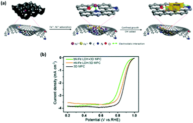 | ||
| Fig. 17 (a) Schematic illustration of the synthesis of nNiFe LDH/3D MPC and (b) ORR LSV curves for nNiFe LDH/3D MPC, bNiFe LDH + 3D MPC and 3D MPC in 0.1 M KOH at a scan rate of 5 mV s−1 with a rotation speed of 900 rpm. (Reproduced with permission (ref. 123) Copyright Royal Society of Chemistry (2018).) | ||
The ORR performance of the nNiFe LDH/3D MPC was also compared to the 3D MPC platform and a NiFe LDH catalyst with the 3D MPC added after synthesis. The ORR performance of the nNiFe LDH/3D MPC was indeed better than the bNiFe LDH + 3D MPC, again indicating that the route taken to yield LDH catalysts for the ORR have a significant influence upon it's catalytic properties, Fig. 17(b). Unfortunately, and also stated by the authors, the LDH based materials under-performed when compared to the 3D MPC platform. Perhaps with further aids, such as CNT or other conductive aids, this NiFe based LDH could achieve better ORR potentials.
The use of ternary metal LDH catalysts for the ORR have been explored. Two studies based on different ternary LDH catalysts are reviewed herein to highlight the effect of the fabrication techniques on these ternary LDH materials toward the ORR.124,125 In the first study, the effect of varying the molar ratio of two of the three metals present in a CoNiFe material on the ORR was investigated. In this study, three CoNiFe LDHs was synthesis by a two-step method involving a co-precipitation process and then a thermal annealing process. During the fabrication procedure the molar ratio of the Co2+![[thin space (1/6-em)]](https://www.rsc.org/images/entities/char_2009.gif) :
:![[thin space (1/6-em)]](https://www.rsc.org/images/entities/char_2009.gif) Ni2+ (Ni2+ molar percentages (sample name): 33% (M1), 27% (M2) and 47% (M3)) was varied and the molar percentage of the Fe3+ remained constant and as a result a reverse spinel structure for all of the CoNiFe LDH catalysts were produced. The ORR activity of the three CoNiFe LDH materials were probed on a GC disk in 0.5 M KOH. The ORR evaluation revealed a trend with respect to the percentage of Ni2+ in the LDH; the larger percentage of Ni2+ yielded the best performing catalysts while the smallest amount of Ni2+ (or the largest amount of Co2+) produced the worst ORR catalyst. Hence the trend observed toward the ORR performance of the catalysts, from best to worst, is M3 < M1 < M2. XPS analysis provided a rational explanation for this outcome; the authors correlated the higher amount of NiO and octahedral Co3+ sites in the spinal structure of the M3 material to be the cause of the increased ORR activity i.e. the active ORR site. The authors suggested that this result indicates more oxygen vacancies are present on the surface of the material for ORR to proceed when compared to the M2 and M1 materials as these materials contained less NiO/Co3+ sites. This study suggests that approx. a 50
Ni2+ (Ni2+ molar percentages (sample name): 33% (M1), 27% (M2) and 47% (M3)) was varied and the molar percentage of the Fe3+ remained constant and as a result a reverse spinel structure for all of the CoNiFe LDH catalysts were produced. The ORR activity of the three CoNiFe LDH materials were probed on a GC disk in 0.5 M KOH. The ORR evaluation revealed a trend with respect to the percentage of Ni2+ in the LDH; the larger percentage of Ni2+ yielded the best performing catalysts while the smallest amount of Ni2+ (or the largest amount of Co2+) produced the worst ORR catalyst. Hence the trend observed toward the ORR performance of the catalysts, from best to worst, is M3 < M1 < M2. XPS analysis provided a rational explanation for this outcome; the authors correlated the higher amount of NiO and octahedral Co3+ sites in the spinal structure of the M3 material to be the cause of the increased ORR activity i.e. the active ORR site. The authors suggested that this result indicates more oxygen vacancies are present on the surface of the material for ORR to proceed when compared to the M2 and M1 materials as these materials contained less NiO/Co3+ sites. This study suggests that approx. a 50![[thin space (1/6-em)]](https://www.rsc.org/images/entities/char_2009.gif) :
:![[thin space (1/6-em)]](https://www.rsc.org/images/entities/char_2009.gif) 50 ratio of Ni
50 ratio of Ni![[thin space (1/6-em)]](https://www.rsc.org/images/entities/char_2009.gif) :
:![[thin space (1/6-em)]](https://www.rsc.org/images/entities/char_2009.gif) Co is optimum in the ternary CoNiFe LDH is optimum for the ORR.
Co is optimum in the ternary CoNiFe LDH is optimum for the ORR.
In the second study, a similar co-precipitation fabrication process to produce the ternary metal LDH materials was utilised compared to the aforementioned study however this time a CoNiMn LDH based catalysts was fabricated. Additionally this work set out to investigate the effect induced by reduced graphene oxide and poly-pyrrole on the CoNiMn LDH towards ORR.125 The reduced graphene oxide (rGO) component of the composite LDH material was prepared by the Hummers method while the poly-pyrrole was fabricated by polymerising pyrrole. Subsequently, the Co, Ni and Mn metal salts were then added to the rGO in deionised water and finally the poly-pyrrole (PPY). To produce the composite LDH the three components were added together with NaOH to induce a co-precipitation reaction, the composite was then aged for 24 hours under stirring, Fig. 18(a). Additionally, for comparison a PPy/rGO, a CoNiMn–rGO and a CoNiMn-LDH were also fabricated by this method; with the missing component in the materials name omitted from the fabrication route.
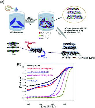 | ||
| Fig. 18 (a) Schematic illustration of fabrication process towards CoNiMn-LDH/PPy/RGO for oxygen reduction reaction and (b) LSV curves of the four samples, 20 wt% Pt/C, and 20 wt% RuO2/C catalyst at 1600 rpm in O2-saturated 0.1 M KOH. (Reproduced with permission (ref. 125) Copyright Elsevier (2017).) | ||
The ORR performance of the CoNiMn–PPy/rGO, PPy/rGO, and CoNiMn–rGO was evaluated alongside state of the art ORR materials, Fig. 18(b). The CoNiMn–rGO mixed with the PPy/rGO post fabrication was also evaluated to determine if the presence of the PPy/rGO was enough to effect the ORR activity of the LDH or if the PPy/rGO needed to be fabricated directly with the LDH. The results showed that the CoNiMn–PPy/rGO LDH composite made directly during synthesis out-performed all of the aforementioned materials with an E1/2 value vs. RHE of ∼0.78 V in 0.1 M KOH. Additionally, the CoNiMn–PPy/rGO LDH composite proved to be a better ORR catalyst than the more expensive and PGM based RuO2/C however, yet again, the state-of-the-art ORR material, Pt/C, was the optimum catalyst. Interesting, the CoNiMn–rGO mixed with the PPy/rGO post fabrication exhibits a huge decrease in its E1/2 value. This study indicates that the fabrication of the composite in situ or post fabrication changes the properties associated with the ORR and that the synthesis of the CoNiMn–PPy/rGO LDH composite in a one-pot synthesis creates synergistic effects toward the ORR which are not observed for the CoNiMn–rGO mixed with the PPy/rGO.
Conclusion and outlook
There has been a significant increase in the utilisation of LDHs as electrocatalysts for O2 electrode reactions; the OER and ORR, in alkaline electrolyte in the recent years. It is clear from this review that even small quantities of simple additives, i.e. rGO or CNTs, during the synthetic process, the use of high surface area supports and/or exfoliation of these layered materials changes the resulting catalytic properties. As observed from the various articles reviewed here, these modifications during the synthesis of the LDHs/LDH-based composites can propel the activity exhibited close to the expensive and scarce state-of-the-art catalysts e.g. RuO2 for OER and Pt for ORR. Further research into the optimisation and/or modification of these interesting materials may open avenues to lead the scientific community in finding a promising cheap and highly active materials for the two aforementioned O2 reactions; a vital step towards the efficient running of a future hydrogen economy.Conflicts of interest
There are no conflicts to declare.Acknowledgements
This work emanated from financial support from the Advanced Functional Nanorobots project (reg. no. CZ.02.1.01/0.0/0.0/15_003/0000444 financed by the EFRR). M. P. B. would also like to acknowledge the European Structural and Investment Funds, OP RDE-funded project ‘ChemJets’ (No. CZ.02.2.69/0.0/0.0/16_027/0008351). Z. S. was supported by Czech Science Foundation (GACR No. 17-11456S) and by the financial support of the Neuron Foundation for science support.Notes and references
- I. E. Agency, 2017.
- K. Harrison and J. I. Levene, Solar Hydrogen Generation: Toward a Renewable Energy Future, 2008 Search PubMed.
- S. Shafiee and E. Topal, Energy Policy, 2009, 37, 181–189 CrossRef.
- I. Dincer and C. Acar, Int. J. Hydrogen Energy, 2015, 40, 11094–11111 CrossRef CAS.
- R. Subbaraman, D. Tripkovic, K.-C. Chang, D. Strmcnik, A. P. Paulikas, P. Hirunsit, M. Chan, J. Greeley, V. Stamenkovic and N. M. Markovic, Nat. Mater., 2012, 11, 550 CrossRef CAS PubMed.
- A. Faur Ghenciu, Curr. Opin. Solid State Mater. Sci., 2002, 6, 389–399 CrossRef CAS.
- M. S. Dresselhaus and I. L. Thomas, Nature, 2001, 414, 332–337 CrossRef CAS PubMed.
- G. Merle, M. Wessling and K. Nijmeijer, J. Membr. Sci., 2011, 377, 1–35 CrossRef CAS.
- K. V. Lykhnytskyi, Hydrogen Materials Science and Chemistry of Carbon Nanomaterials, Springer Netherlands, Dordrecht, 2007 Search PubMed.
- J. Chi and H. Yu, Chin. J. Catal., 2018, 39, 390–394 CrossRef CAS.
- M. E. G. Lyons, R. L. Doyle, D. Fernandez, I. J. Godwin, M. P. Browne and A. Rovetta, Electrochem. Commun., 2014, 45, 60–62 CrossRef CAS.
- D. E. Hall, J. Electrochem. Soc., 1983, 317–321 CrossRef CAS.
- H. Tributsch, Int. J. Hydrogen Energy, 2008, 33, 5911–5930 CrossRef CAS.
- K. Zeng and D. Zhang, Prog. Energy Combust. Sci., 2010, 36, 307–326 CrossRef CAS.
- C. C. L. McCrory, S. Jung, I. M. Ferrer, S. M. Chatman, J. C. Peters and T. F. Jaramillo, J. Am. Chem. Soc., 2015, 137, 4347–4357 CrossRef CAS PubMed.
- C. C. L. McCrory, S. Jung, J. C. Peters and T. F. Jaramillo, J. Am. Chem. Soc., 2013, 135, 16977–16987 CrossRef CAS PubMed.
- C. L. Manzanares Palenzuela, J. Luxa, Z. Sofer and M. Pumera, ACS Appl. Mater. Interfaces, 2018, 10, 17820–17826 CrossRef CAS PubMed.
- I. Roger and M. D. Symes, J. Mater. Chem. A, 2016, 4, 6724–6741 RSC.
- M. S. Burke, S. Zou, L. J. Enman, J. E. Kellon, C. A. Gabor, E. Pledger and S. W. Boettcher, J. Phys. Chem. Lett., 2015, 6, 3737–3742 CrossRef CAS PubMed.
- M. Schalenbach, A. R. Zeradjanin, O. Kasian, S. Cherevko and K. J. J. Mayrhofer, Int. J. Electrochem. Sci., 2018, 13, 1173–1226 CrossRef CAS.
- K. J. Seong, K. Byunghoon, K. Hyunah and K. Kisuk, Adv. Energy Mater., 2018, 8, 1702774 CrossRef.
- M. G. Walter, E. L. Warren, J. R. McKone, S. W. Boettcher, Q. Mi, E. A. Santori and N. S. Lewis, Chem. Rev., 2010, 110, 6446–6473 CrossRef CAS PubMed.
- M. E. G. Lyons, R. L. Doyle, M. P. Browne, I. J. Godwin and A. A. S. Rovetta, Curr. Opin. Electrochem., 2017, 1, 40–45 CrossRef CAS.
- T. Sinigaglia, F. Lewiski, M. E. Santos Martins and J. C. Mairesse Siluk, Int. J. Hydrogen Energy, 2017, 42, 24597–24611 CrossRef CAS.
- A. Demirbas, Energy Sources, Part B, 2017, 12, 172–181 CrossRef CAS.
- T. da Silva Veras, T. S. Mozer, D. da Costa Rubim Messeder dos Santos and A. da Silva César, Int. J. Hydrogen Energy, 2017, 42, 2018–2033 CrossRef CAS.
- X. J. Chua, J. Luxa, A. Y. S. Eng, S. M. Tan, Z. Sofer and M. Pumera, ACS Catal., 2016, 6, 5724–5734 CrossRef CAS.
- K. A. Stoerzinger, L. Qiao, M. D. Biegalski and Y. Shao-Horn, J. Phys. Lett., 2014, 5, 1636–1641 CAS.
- R. R. Rao, M. J. Kolb, N. B. Halck, A. F. Pedersen, A. Mehta, H. You, K. A. Stoerzinger, Z. Feng, H. A. Hansen, H. Zhou, L. Giordano, J. Rossmeisl, T. Vegge, I. Chorkendorff, I. E. L. Stephens and Y. Shao-Horn, Energy Environ. Sci., 2017, 10, 2626–2637 RSC.
- Y. Lee, J. Suntivich, K. J. May, E. E. Perry and Y. Shao-Horn, J. Phys. Lett., 2012, 3, 399–404 CAS.
- M. Escudero-Escribano, A. F. Pedersen, E. A. Paoli, R. Frydendal, D. Friebel, P. Malacrida, J. Rossmeisl, I. E. L. Stephens and I. Chorkendorff, J. Phys. Chem. B, 2018, 122, 947–955 CrossRef PubMed.
- M. E. G. Lyons, R. L. Doyle, D. Fernandez, I. J. Godwin, M. P. Browne and A. Rovetta, Electrochem. Commun., 2014, 45, 56–59 CrossRef CAS.
- Z. Zhao, H. Wu, H. He, X. Xu and Y. Jin, Adv. Funct. Mater., 2014, 24, 4698–4705 CrossRef CAS.
- Z.-Y. Yu, C.-C. Lang, M.-R. Gao, Y. Chen, Q.-Q. Fu, Y. Duan and S.-H. Yu, Energy Environ. Sci., 2018, 11, 1890–1897 RSC.
- L. Wang, T. Du, J. Cheng, X. Xie, B. Yang and M. Li, J. Power Sources, 2015, 280, 550–554 CrossRef CAS.
- Y. Liang, Q. Liu, A. M. Asiri and X. Sun, Electrochim. Acta, 2015, 153, 456–460 CrossRef CAS.
- B. Zhang, X. Zheng, O. Voznyy, R. Comin, M. Bajdich, M. García-Melchor, L. Han, J. Xu, M. Liu, L. Zheng, F. P. García de Arquer, C. T. Dinh, F. Fan, M. Yuan, E. Yassitepe, N. Chen, T. Regier, P. Liu, Y. Li, P. De Luna, A. Janmohamed, H. L. Xin, H. Yang, A. Vojvodic and E. H. Sargent, Science, 2016, 352, 333–337 CrossRef CAS PubMed.
- P. Du, J. Zhang, Y. Liu and M. Huang, Electrochem. Commun., 2017, 83, 11–15 CrossRef CAS.
- N. F. Rosli, C. C. Mayorga-Martinez, N. M. Latiff, N. Rohaizad, Z. Sofer, A. C. Fisher and M. Pumera, ACS Sustainable Chem. Eng., 2018, 6, 7432–7441 CrossRef CAS.
- X. J. Chua and M. Pumera, Phys. Chem. Chem. Phys., 2017, 19, 6610–6619 RSC.
- C. Song and J. Zhang, in PEM Fuel Cell Electrocatalysts and Catalyst Layers: Fundamentals and Applications, ed. J. Zhang, Springer London, London, 2008, pp. 89–134 DOI:10.1007/978-1-84800-936-3_2.
- Y. Jiao, Y. Zheng, M. Jaroniec and S. Z. Qiao, Chem. Soc. Rev., 2015, 44, 2060–2086 RSC.
- E. S. Davydova, S. Mukerjee, F. Jaouen and D. R. Dekel, ACS Catal., 2018, 8(7), 6665–6690 CrossRef CAS.
- C. Domínguez, K. M. Metz, M. K. Hoque, M. P. Browne, L. Esteban-Tejeda, C. K. Livingston, S. Lian, T. S. Perova and P. E. Colavita, ChemElectroChem, 2018, 5, 62–70 CrossRef.
- J. S. Kim, B. Kim, H. Kim and K. Kang, Adv. Energy Mater., 2018, 8(11), 1702774 CrossRef.
- J.-X. Feng, H. Xu, Y.-T. Dong, S.-H. Ye, Y.-X. Tong and G.-R. Li, Angew. Chem., Int. Ed., 2016, 55, 3694–3698 CrossRef CAS PubMed.
- J.-X. Feng, S.-H. Ye, H. Xu, Y.-X. Tong and G.-R. Li, Adv. Mater., 2016, 28, 4698–4703 CrossRef CAS PubMed.
- X.-F. Lu, L.-F. Gu, J.-W. Wang, J.-X. Wu, P.-Q. Liao and G.-R. Li, Adv. Mater., 2017, 29, 1604437 CrossRef PubMed.
- S.-H. Ye, Z.-X. Shi, J.-X. Feng, Y.-X. Tong and G.-R. Li, Angew. Chem., Int. Ed., 2018, 57, 2672–2676 CrossRef CAS PubMed.
- M. Xing, L.-B. Kong, M.-C. Liu, L.-Y. Liu, L. Kang and Y.-C. Luo, J. Mater. Chem. A, 2014, 2, 18435–18443 RSC.
- R. D. L. Smith, M. S. Prévot, R. D. Fagan, S. Trudel and C. P. Berlinguette, J. Am. Chem. Soc., 2013, 135, 11580–11586 CrossRef CAS PubMed.
- L. Trotochaud, J. K. Ranney, K. N. Williams and S. W. Boettcher, J. Am. Chem. Soc., 2012, 134, 17253–17261 CrossRef CAS PubMed.
- C. Bocca, A. Barbucci, M. Delucchi and G. Cerisola, Int. J. Hydrogen Energy, 1999, 24, 21–26 CrossRef CAS.
- M. Gao, W. Sheng, Z. Zhuang, Q. Fang, S. Gu, J. Jiang and Y. Yan, J. Am. Chem. Soc., 2014, 136, 7077–7084 CrossRef CAS PubMed.
- S. Klaus, M. W. Louie, L. Trotochaud and A. T. Bell, J. Phys. Chem. C, 2015, 119, 18303–18316 CrossRef CAS.
- J. R. Swierk, S. Klaus, L. Trotochaud, A. T. Bell and T. D. Tilley, J. Phys. Chem. C, 2015, 119, 19022–19029 CrossRef CAS.
- T. Takashima, K. Hashimoto and R. Nakamura, J. Am. Chem. Soc., 2012, 134, 1519–1527 CrossRef CAS PubMed.
- T. T. H. Hoang and A. A. Gewirth, ACS Catal., 2016, 6, 1159–1164 CrossRef CAS.
- M. K. Bates, Q. Jia, H. Doan, W. Liang and S. Mukerjee, ACS Catal., 2016, 6, 155–161 CrossRef CAS.
- M. Browne, R. J. Cullen, R. L. Doyle, P. E. Colavita and M. E. G. Lyons, ECS Trans., 2013, 53, 59–77 CrossRef.
- M. P. Browne, H. Nolan, G. S. Duesberg, P. E. Colavita and M. E. G. Lyons, ACS Catal., 2016, 6, 2408–2415 CrossRef CAS.
- V. Nicolosi, M. Chhowalla, M. G. Kanatzidis, M. S. Strano and J. N. Coleman, Science, 2013, 340, 1226419 CrossRef.
- K. Kalantar-zadeh, J. Z. Ou, T. Daeneke, A. Mitchell, T. Sasaki and M. S. Fuhrer, Appl. Mater. Today, 2016, 5, 73 CrossRef.
- M. Zeng, Y. Xiao, J. Liu, K. Yang and L. Fu, Chem. Rev., 2018, 118(13), 6236–6296 CrossRef CAS PubMed.
- S. Yang, Y. Gong, Z. Liu, L. Zhan, D. P. Hashim, L. Ma, R. Vajtai and P. M. Ajayan, Nano Lett., 2013, 13, 1596–1601 CrossRef CAS PubMed.
- F. Song and X. Hu, J. Am. Chem. Soc., 2014, 136, 16481–16484 CrossRef CAS PubMed.
- F. Song and X. Hu, Nat. Commun., 2014, 5, 4477 CrossRef CAS PubMed.
- Q. Wang and D. O’Hare, Chem. Rev., 2012, 112, 4124–4155 CrossRef CAS PubMed.
- R. Ma, Z. Liu, K. Takada, N. Iyi, Y. Bando and T. Sasaki, J. Am. Chem. Soc., 2007, 129, 5257–5263 CrossRef CAS PubMed.
- J. Coelho, B. Mendoza-Sánchez, H. Pettersson, A. Pokle, E. K. McGuire, E. Long, L. McKeon, A. P. Bell and V. Nicolosi, 2D Mater., 2015, 2, 2 Search PubMed.
- L. Zhu, C. K. Nuo Peh, T. Zhu, Y.-F. Lim and G. W. Ho, J. Mater. Chem. A, 2017, 5, 8343–8351 RSC.
- H. Jiang, H. Ma, Y. Jin, L. Wang, F. Gao and Q. Lu, Sci. Rep., 2016, 6, 31751 CrossRef CAS PubMed.
- Y. Zhu, C. Cao, S. Tao, W. Chu, Z. Wu and Y. Li, Sci. Rep., 2014, 4, 5787 CrossRef CAS PubMed.
- Z. Tianran, G. Xiaoming, Z. Zhao, T. N. Neng, L. Zhaolin, F. Adrian and L. J. Yang, ChemCatChem, 2018, 10, 422–429 CrossRef.
- S. Jaśkaniec, C. Hobbs, A. Seral-Ascaso, J. Coelho, M. P. Browne, D. Tyndall, T. Sasaki and V. Nicolosi, Sci. Rep., 2018, 8, 4179 CrossRef PubMed.
- D. McAteer, I. J. Godwin, Z. Ling, A. Harvey, L. He, C. S. Boland, V. Vega-Mayoral, B. Szydłowska, A. A. Rovetta, C. Backes, J. B. Boland, X. Chen, M. E. G. Lyons and J. N. Coleman, Adv. Energy Mater., 2018, 8(15), 1702965 CrossRef.
- M. H. Alfaruqi, S. Islam, D. Y. Putro, V. Mathew, S. Kim, J. Jo, S. Kim, Y.-K. Sun, K. Kim and J. Kim, Electrochim. Acta, 2018, 276, 1–11 CrossRef CAS.
- A. Harvey, X. He, I. J. Godwin, C. Backes, D. McAteer, N. C. Berner, N. McEvoy, A. Ferguson, A. Shmeliov, M. E. G. Lyons, V. Nicolosi, G. S. Duesberg, J. F. Donegan and J. N. Coleman, J. Mater. Chem. A, 2016, 4, 11046–11059 RSC.
- A. A. S. Rovetta, M. P. Browne, A. Harvey, I. J. Godwin, J. N. Coleman and M. E. G. Lyons, Nanotechnology, 2017, 28, 375401 CrossRef CAS PubMed.
- Y. Jia, L. Zhang, G. Gao, H. Chen, B. Wang, J. Zhou, M. T. Soo, M. Hong, X. Yan, G. Qian, J. Zou, A. Du and X. Yao, Adv. Mater., 2017, 29, 1700017 CrossRef PubMed.
- V. V. Atuchin, T. A. Gavrilova, T. I. Grigorieva, N. V. Kuratieva, K. A. Okotrub, N. V. Pervukhina and N. V. Surovtsev, J. Cryst. Grow., 2011, 318, 987–990 CrossRef CAS.
- G. P. Wirtz, L. B. Sis and J. S. Wheeler, J. Catal., 1975, 38, 196–205 CrossRef CAS.
- H. Tao, Y. Zhang, Y. Gao, Z. Sun, C. Yan and J. Texter, Phys. Chem. Chem. Phys., 2017, 19, 921–960 RSC.
- S. Chandrasekaran, E. J. Kim, J. S. Chung, C. R. Bowen, B. Rajagopalan, V. Adamaki, R. D. K. Misra and S. H. Hur, J. Mater. Chem. A, 2016, 4, 13271–13279 RSC.
- F.-C. Shen, Y. Wang, Y.-J. Tang, S.-L. Li, Y.-R. Wang, L.-Z. Dong, Y.-F. Li, Y. Xu and Y.-Q. Lan, ACS Energy Lett., 2017, 2, 1327–1333 CrossRef CAS.
- T. Kidd, A. O'Shea, K. Boyle, J. Wallace and L. Strauss, Nanoscale Res. Lett., 2011, 6, 294 CrossRef PubMed.
- C. Zhao, H. Zhang, W. Si and H. Wu, Nat. Commun., 2016, 7, 12543 CrossRef CAS PubMed.
- H. Kim, J. Hong, K.-Y. Park, H. Kim, S.-W. Kim and K. Kang, Chem. Rev., 2014, 114, 11788–11827 CrossRef CAS PubMed.
- F. Wang, S. Xiao, Y. Hou, C. Hu, L. Liu and Y. Wu, RSC Adv., 2013, 3, 13059–13084 RSC.
- S. Miyazaki, S. Kikkawa and M. Koizumi, Synth. Met., 1983, 6, 211–217 CrossRef CAS.
- D. Montasserasadi, D. Mohanty, A. Huq, L. Heroux, E. A. Payzant and J. B. Wiley, Inorg. Chem., 2014, 53, 1773–1778 CrossRef CAS PubMed.
- H. T. Lee, S. Kwon, C. M. Youn, T. Choi and J. H. Lee, Eur. J. Inorg. Chem., 2017, 2184–2189 CrossRef CAS.
- J. Luxa, P. Vosecký, V. Mazánek, D. Sedmidubský, M. Pumera and Z. Sofer, ACS Catal., 2018, 8, 2774–2781 CrossRef CAS.
- M. P. Browne and A. Mills, J. Mater. Chem. A, 2018, 6, 14162–14169 RSC.
- A. Corina, B. Stefan, V. Edgar, M. Justus, V. Eugeniu, K. Bharathi, M. Sandra and S. Wolfgang, Angew. Chem., Int. Ed., 2017, 56, 11258–11262 CrossRef PubMed.
- I. J. Godwin and M. E. G. Lyons, Electrochem. Commun., 2013, 32, 39–42 CrossRef CAS.
- R. L. Doyle, I. J. Godwin, M. P. Brandon and M. E. G. Lyons, Phys. Chem. Chem. Phys., 2013, 15, 13737–13783 RSC.
- S. R. Mellsop, A. Gardiner, B. Johannessen and A. T. Marshall, Electrochim. Acta, 2015, 168, 356–364 CrossRef CAS.
- S. Klaus, Y. Cai, M. W. Louie, L. Trotochaud and A. T. Bell, J. Phys. Chem. C, 2015, 119, 7243–7254 CrossRef CAS.
- M. P. Browne, S. Stafford, M. O'Brien, H. Nolan, N. C. Berner, G. S. Duesberg, P. E. Colavita and M. E. G. Lyons, J. Mater. Chem. A, 2016, 4, 11397–11407 RSC.
- D. A. Corrigan, J. Electrochem. Soc., 1987, 134, 377–384 CrossRef CAS.
- L. Trotochaud, S. L. Young, J. K. Ranney and S. W. Boettcher, J. Am. Chem. Soc., 2014, 136, 6744–6753 CrossRef CAS PubMed.
- X. Lu, W.-L. Yim, B. H. R. Suryanto and C. Zhao, J. Am. Chem. Soc., 2015, 137, 2901–2907 CrossRef CAS PubMed.
- Z. Yunxuan, C. Chao, T. Fei, Z. Yufei, C. Guangbo, S. Run, G. I. N. Waterhouse, H. Weifeng and Z. Tierui, Adv. Energy Mater., 2017, 7, 1700005 CrossRef.
- M. Huynh, C. Shi, S. J. L. Billinge and D. G. Nocera, J. Am. Chem. Soc., 2015, 137, 14887–14904 CrossRef CAS PubMed.
- R. Frydendal, L. C. Seitz, D. Sokaras, T. C. Weng, D. Nordlund, I. Chorkendorff, I. E. L. Stephens and T. F. Jaramillo, Electrochim. Acta, 2017, 230, 22–28 CrossRef CAS.
- Y. Meng, W. Song, H. Huang, Z. Ren, S.-Y. Chen and S. L. Suib, J. Am. Chem. Soc., 2014, 136, 11452–11464 CrossRef CAS PubMed.
- W. Hui, Z. Jiajia, H. Xudong, Z. Xiaodong, X. Junfeng, P. Bicai and X. Yi, Angew. Chem., Int. Ed., 2015, 54, 1195–1199 CrossRef PubMed.
- H.-Y. Su, Y. Gorlin, I. C. Man, F. Calle-Vallejo, J. K. Norskov, T. F. Jaramillo and J. Rossmeisl, Phys. Chem. Chem. Phys., 2012, 14, 14010–14022 RSC.
- A. C. Thenuwara, E. B. Cerkez, S. L. Shumlas, N. H. Attanayake, I. G. McKendry, L. Frazer, E. Borguet, Q. Kang, R. C. Remsing, M. L. Klein, M. J. Zdilla and D. R. Strongin, Angew. Chem., Int. Ed., 2016, 55, 10381–10385 CrossRef CAS PubMed.
- L. Su, H. Du, C. Tang, K. Nan, J. Wu and C. Ming Li, J. Colloid Interface Sci., 2018, 528, 36–44 CrossRef CAS PubMed.
- Z. Zhang, T. Zhang and J. Y. Lee, ACS Appl. Nano Mater., 2018, 1, 751–758 CrossRef CAS.
- N. Han, F. Zhao and Y. Li, J. Mater. Chem. A, 2015, 3, 16348–16353 RSC.
- M. Luo, Z. Cai, C. Wang, Y. Bi, L. Qian, Y. Hao, L. Li, Y. Kuang, Y. Li, X. Lei, Z. Huo, W. Liu, H. Wang, X. Sun and X. Duan, Nano Res., 2017, 10, 1732–1739 CrossRef CAS.
- X. Lu and C. Zhao, Nat. Commun., 2015, 6, 6616 CrossRef CAS PubMed.
- Y. Vlamidis, E. Scavetta, M. Gazzano and D. Tonelli, Electrochim. Acta, 2016, 188, 653–660 CrossRef CAS.
- Y. Fengkai, S. Kirill, S. Ilya, A. Hendrik, B. Alexander, O. Kevin, X. Wei, M. Justus, G. Wolfgang, C. B. Roldan, S. Wolfgang and M. Martin, ChemSusChem, 2017, 10, 156–165 CrossRef PubMed.
- M. S. Burke, M. G. Kast, L. Trotochaud, A. M. Smith and S. W. Boettcher, J. Am. Chem. Soc., 2015, 137, 3638–3648 CrossRef CAS PubMed.
- A. M. Ullman, C. N. Brodsky, N. Li, S.-L. Zheng and D. G. Nocera, J. Am. Chem. Soc., 2016, 138, 4229–4236 CrossRef CAS PubMed.
- T. Zhan, Y. Zhang, X. Liu, S. Lu and W. Hou, J. Power Sources, 2016, 333, 53–60 CrossRef CAS.
- L. Wang, C. K. Chua, B. Khezri, R. D. Webster and M. Pumera, Electrochem. Commun., 2016, 62, 17–20 CrossRef CAS.
- S. Jiri, L. Jan, P. Martin and S. Zdeněk, Chem. – Eur. J., 2018, 24, 5992–6006 CrossRef PubMed.
- W. Wang, Y. Liu, J. Li, J. Luo, L. Fu and S. Chen, J. Mater. Chem. A, 2018, 6, 14299–14306 RSC.
- M. Oliver-Tolentino, J. Vazquez-Samperio, M. Tufiño-Velázquez, J. Flores-Moreno, L. Lartundo-Rojas and R. de G. Gonzalez-Huerta, J. Appl. Electrochem., 2018, 48, 947–957 CrossRef CAS.
- X. Jia, S. Gao, T. Liu, D. Li, P. Tang and Y. Feng, Electrochim. Acta, 2017, 245, 59–68 CrossRef CAS.
| This journal is © The Royal Society of Chemistry 2019 |


