 Open Access Article
Customizing a Li–metal battery that survives practical operating conditions for electric vehicle applications†
Jang-Yeon
Hwang‡
 a,
Seong-Jin
Park‡
a,
Chong S.
Yoon
*b and
Yang-Kook
Sun
a,
Seong-Jin
Park‡
a,
Chong S.
Yoon
*b and
Yang-Kook
Sun
 *a
*a
aDepartment of Energy Engineering, Hanyang University, Seoul 04763, Republic of Korea. E-mail: yksun@hanyang.ac.kr
bDepartment of Materials Science and Engineering, Hanyang University, Seoul 04763, Republic of Korea. E-mail: csyoon@hanyang.ac.kr
First published on 7th June 2019
Abstract
We propose a new breakthrough in realizing a practical Li–metal battery (LMB) capable of fast charging while delivering a high energy density. We used an electrolyte consisting of 1 M LiPF6 and 0.05 M lithium difluoro(oxalate)borate dissolved in a mixture of ethyl methyl carbonate and fluoroethylene carbonate to ensure the formation of a stable and robust solid electrolyte interphase (SEI) layer on the anode surface. Pretreatment of the Li–metal anode with LiNO3 adds a prior Li2O-rich SEI layer that provides the required mechanical strength to prevent premature SEI layer breakdown. An Al-doped full-concentration-gradient Li[Ni0.75Co0.10Mn0.15]O2 cathode provides the necessary cycling stability at a high cathode loading. By integrating these components, we produced an LMB that allowed a high areal capacity of 4.1 mA h cm−2 with an unprecedented cycling stability over 300 cycles at a high current density of 3.6 mA cm−2 (full charge–discharge in 2 h). We believe that the findings presented herein provide new perspectives for the development of practical LMBs that satisfy the capacity and charging rate requirements for future electric vehicles.
Broader contextLi metal, with the theoretical capacity of 3860 mA h g−1, is considered to be an alternative anode for high-energy-density batteries. A Li metal battery (LMB), when used in electric vehicle (EVs), needs to survive the practical operating conditions. However, Li dendrite growth induces poor cycling efficiency at fast charging rates and at high active material loadings, hindering the application of LMBs in EVs. We used a modified organic electrolyte and pretreatment of Li metal to form a stable and robust solid electrolyte interphase layer on the Li anode surface. Together with an Al-doped full-concentration-gradient Li[Ni0.75Co0.10Mn0.15]O2 cathode, an LMB capable of an areal capacity of 4.1 mA h cm−2 with unprecedented cycling stability over 300 cycles at a high current density of 3.6 mA cm−2 was constructed. To demonstrate the commercial viability of the proposed LMB, the LMB was also cycled in a pouch-type full cell for 500 cycles while maintaining 90% of the initial capacity. The performance of the LMB easily surpasses those of LMB batteries reported in the literature to date, thus bringing us a step closer to resolving the driving range and fast charging issues that have plagued the current fleet of EVs using the proposed LMB. |
Introduction
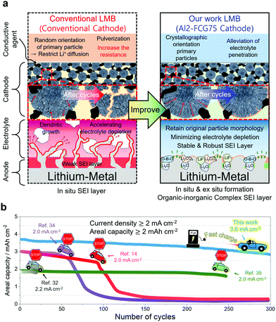
Zero tolerance for carbon-dioxide emissions and reducing the dependence on fossil fuels are obliging governments around the world to increasingly mandate automakers to produce and sell electric vehicles (EVs);1 however, the consumer response to EVs has not been favorable due to the limitations of the current Li-ion battery (LIB) technology. As an alternative for the current commercial LIBs,2 rechargeable batteries using lithium metal as an anode were suggested for future high-energy-density batteries for EVs, largely because of the lithium–metal anode's exceptionally high specific capacity (3860 mA h g−1) compared to that (372 mA h g−1) of the conventional graphite-based LiC6 anode.3,4 Faster reaction kinetics stemming from a low redox potential (−3.004 V vs. standard hydrogen electrode) and high electronic conductivity of Li are also potentially favorable for reducing the charging time. Despite their promise, however, the practical application of LMBs has been proven difficult owing to the inferior cycling stability and safety hazard of Li metal, which is mainly related to the high reactivity of Li metal with electrolyte components, as well as the uncontrolled growth of Li dendrites during the charging process.5 To mitigate interfacial instabilities of the Li anode, a myriad of engineering strategies have been introduced.6–9 Despite this promise, overcoming the inherent Li instability still requires the formation of a stable solid electrolyte interphase (SEI) layer to protect the Li metal surface and suppress the detrimental dendritic growth.10 Moreover, a successful LMB also requires a robust cathode that can deliver a large specific capacity with cycling stability. Although sulfur and air cathodes have been proposed, Li–S and Li–air batteries aggravate the Li instability owing to further attack by polysulfide anions11 and superoxide radical anions,12 thus limiting these batteries to laboratory practices. An optimal cathode candidate would be a Li[NixCoyMn1−x−y]O2 (NCM) layered cathode, which may offer a relatively low energy density compared to those of Li–S and Li–air batteries, but provide a reliability that has been extensively field-tested in commercial EVs.Herein, we propose a Li/NCM battery that enables fast charging and extends the driving range of an EV. To mitigate the Li instability, formation of a robust and stable SEI layer is enabled by first pre-treating the Li metal with LiNO3 and using an electrolyte consisting of 1 M LiPF6 and 0.05 M lithium difluoro(oxalate)borate (LiDFOB) dissolved in a mixture of ethyl methyl carbonate (EMC) and fluoroethylene carbonate (FEC). In our proposed LMB, an Al-doped full-concentration-gradient Li[Ni0.75Co0.10Mn0.15]O2 cathode (called Al2-FCG75 hereafter), whose chemical composition varies continuously to accommodate the Ni-rich core for high capacity and the Mn-rich surface for capacity retention, is selected because of its outstanding long-term cycling stability while generating a discharge capacity in excess of 210 mA h g−1. The radially oriented primary particles combined with their strong crystallographic texture, which are signature microstructural features for FCG cathodes, ensure high electrochemical activity, structural stability and mechanical robustness. The physicochemical properties of the Al2-FCG75 cathode are included in Fig. S1–S4 (ESI†). Upon integrating the stabilized Li–metal anode with the Al2-FCG75 cathode, as described in Fig. 1, the proposed Li/NCM battery exhibits an unprecedented high areal capacity and excellent cycling stability at an extremely high current density. The performance of our LMB easily surpasses those of LMB batteries reported in the literature to date, thus bringing us a step closer to resolving the drive range and fast charging issues that have plagued the current fleet of EVs.
Results and discussion
Formation of a stable SEI layer via in situ and ex situ routes
The previously developed FEC-based electrolyte, 1 M LiPF6 dissolved in EMC![[thin space (1/6-em)]](https://www.rsc.org/images/entities/char_2009.gif) :
:![[thin space (1/6-em)]](https://www.rsc.org/images/entities/char_2009.gif) FEC = 3
FEC = 3![[thin space (1/6-em)]](https://www.rsc.org/images/entities/char_2009.gif) :
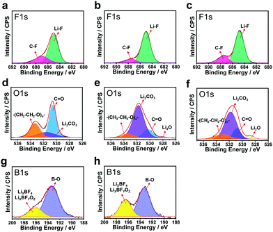
:![[thin space (1/6-em)]](https://www.rsc.org/images/entities/char_2009.gif) 1 (volume ratio) (hereafter denoted as EF-31) was further improved by the addition of 0.05 M LiDFOB as an additive to promote the formation of organic–inorganic complexes in the SEI layer (this electrolyte is hereafter denoted as EF-31-D). In addition, a Li2O-rich SEI layer was formed by an ex situ route by immersing the Li–metal anode in 3 M LiNO3 dissolved in diethylene glycol dimethyl ether (DEGDME) electrolyte for 5 h. Three different Li/Li symmetric cells: (1) bare-Li/EF-31/bare-Li (sample A), (2) bare-Li/EF-31-D/bare-Li (sample B), and (3) LiNO3-treated Li/EF-31-D/LiNO3-treated Li (sample C), were assembled to analyze their respective SEI layers, that were accumulated directly on the Li surface after the 1st deposition, using X-ray photoelectron spectroscopy (XPS) (Fig. 2). In the F 1s spectra (Fig. 2a–c), a strong peak at 684.8 eV corresponding to LiF is detected for all three samples, which is attributed to the presence of the LiPF6 salt and FEC solvent in the electrolyte solution.13,14 In contrast, substantial differences in the three SEI layers were inferred from the respective O 1s spectra (Fig. 2d–f). In the O 1s spectrum of sample A, two strong peaks are observed at 530.5 and 533.5 eV corresponding to the carbonyl oxygen (C
1 (volume ratio) (hereafter denoted as EF-31) was further improved by the addition of 0.05 M LiDFOB as an additive to promote the formation of organic–inorganic complexes in the SEI layer (this electrolyte is hereafter denoted as EF-31-D). In addition, a Li2O-rich SEI layer was formed by an ex situ route by immersing the Li–metal anode in 3 M LiNO3 dissolved in diethylene glycol dimethyl ether (DEGDME) electrolyte for 5 h. Three different Li/Li symmetric cells: (1) bare-Li/EF-31/bare-Li (sample A), (2) bare-Li/EF-31-D/bare-Li (sample B), and (3) LiNO3-treated Li/EF-31-D/LiNO3-treated Li (sample C), were assembled to analyze their respective SEI layers, that were accumulated directly on the Li surface after the 1st deposition, using X-ray photoelectron spectroscopy (XPS) (Fig. 2). In the F 1s spectra (Fig. 2a–c), a strong peak at 684.8 eV corresponding to LiF is detected for all three samples, which is attributed to the presence of the LiPF6 salt and FEC solvent in the electrolyte solution.13,14 In contrast, substantial differences in the three SEI layers were inferred from the respective O 1s spectra (Fig. 2d–f). In the O 1s spectrum of sample A, two strong peaks are observed at 530.5 and 533.5 eV corresponding to the carbonyl oxygen (C![[double bond, length as m-dash]](https://www.rsc.org/images/entities/char_e001.gif) O) and ether oxygen (–(CH2–CH2–O)n–) groups from compounds that are likely generated from the decomposition of the carbonate solvent.15 When 0.05 M LiDFOB was introduced into the EF-31 electrolyte, the intensity of the peaks related to the organic complexes reduced significantly whereas the peak at 531.8 eV corresponding to Li2CO3 dominated the spectra of both sample B and C. The F 1s and O 1s XPS spectra suggest that the LiDFOB additive promotes the development of an inorganic-rich SEI layer, which is particularly rich in Li2CO3 and LiF. According to a previous report, the electrochemical reduction of LiDFOB salt in an FEC-based electrolyte indeed produces LiF- and Li2CO3-rich compounds; these compounds significantly improve the robustness of the SEI layer on the Li–metal surface, because they are less soluble in solvents.16 The B 1s spectra of both samples B and C (Fig. 2g and h) show two strong peaks at 193.2 and 196.4 eV that correspond to fluorine-containing inorganic borates such as LixBOy or LixBOyFz species originating from the decomposition of LiDFOB.17,18 The Fourier transform infrared (FTIR) spectrum of the Li surface in contact with the EF-31-D electrolyte (Fig. S5, ESI†) also clearly revealed peaks associated with C–O–C stretching and O–B–O bending, thus confirming the presence of cross-linked oligomeric borates in the SEI layer. These cross-linked oligomeric borates are believed to render the SEI layer elastic and electrically conductive.19
O) and ether oxygen (–(CH2–CH2–O)n–) groups from compounds that are likely generated from the decomposition of the carbonate solvent.15 When 0.05 M LiDFOB was introduced into the EF-31 electrolyte, the intensity of the peaks related to the organic complexes reduced significantly whereas the peak at 531.8 eV corresponding to Li2CO3 dominated the spectra of both sample B and C. The F 1s and O 1s XPS spectra suggest that the LiDFOB additive promotes the development of an inorganic-rich SEI layer, which is particularly rich in Li2CO3 and LiF. According to a previous report, the electrochemical reduction of LiDFOB salt in an FEC-based electrolyte indeed produces LiF- and Li2CO3-rich compounds; these compounds significantly improve the robustness of the SEI layer on the Li–metal surface, because they are less soluble in solvents.16 The B 1s spectra of both samples B and C (Fig. 2g and h) show two strong peaks at 193.2 and 196.4 eV that correspond to fluorine-containing inorganic borates such as LixBOy or LixBOyFz species originating from the decomposition of LiDFOB.17,18 The Fourier transform infrared (FTIR) spectrum of the Li surface in contact with the EF-31-D electrolyte (Fig. S5, ESI†) also clearly revealed peaks associated with C–O–C stretching and O–B–O bending, thus confirming the presence of cross-linked oligomeric borates in the SEI layer. These cross-linked oligomeric borates are believed to render the SEI layer elastic and electrically conductive.19
Hence, the reduction of the LiDFOB additive induced the emergence of organic–inorganic complexes that effectively passivated the Li metal surface.20 To further assess the effect of LiDFOB on the cycling stability, average Li coulombic efficiency (CE) values were determined from Li/Cu cells using the method reported by Zhang et al.21 The average CEs for EF-31 and EF-31-D were found to be 94.6% and 98.1%, respectively; this result confirms that the addition of LiDFOB into EF-31 improves the stability and electrical conductivity of the SEI layer formed in situ (Fig. S6, ESI†).
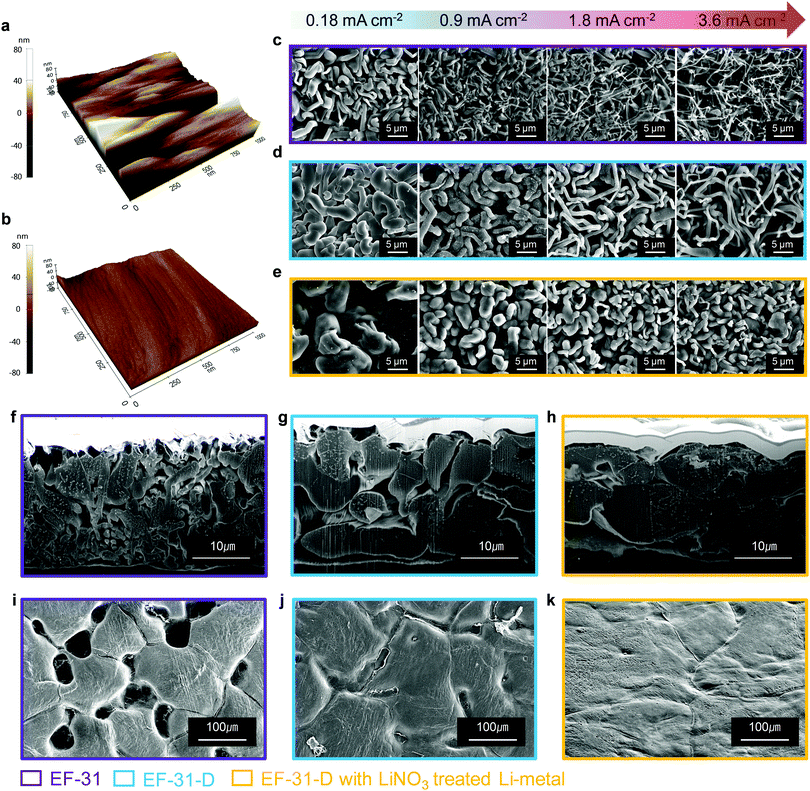
We further improved the robustness of the SEI layer by forming an inorganic compound, particularly Li2O, via an ex situ route. It is well known that Li2O is beneficial for building a robust and stable SEI by preventing excessive decomposition of the electrolyte and enabling a dendrite-free Li deposit morphology.22 A few studies on LMBs using LiNO3 dissolved in ether-based electrolytes have been reported; however, the application of this method to LMBs based on high-voltage NCM cathodes is still difficult owing to the insolubility of LiNO3 in carbonate-based electrolytes and the limited potential window of the ether solvent (∼3.8 V). In order to take advantage of using LiNO3 as an additive while avoiding the disadvantages, we prepared an Li2O-rich SEI via an ex situ route. The topographic images obtained by atomic force microscopy (AFM) in Fig. 3a and b, show that the bare Li–metal has a rough morphology with deep ridges whereas the Li–metal pretreated with LiNO3 shows a uniform and smooth surface. This uniform and flat surface ensures spatially uniform ionic conductivity and current density distribution on the surface of the lithium anode during cycling.23,24 As a result, lithium could be uniformly deposited on and stripped from the entire anode surface, thus improving the cycling stability of the Li–metal anode by suppressing the dendritic Li growth. The mechanical strength of the LiNO3-treated Li anode was estimated using nano-indentation analysis. The difference between the relative mechanical strength of bare and LiNO3-treated Li–metal was determined by analyzing the working test force vs. displacement data recorded from the material surface (see the Fig. S7, ESI†). The LiNO3-treated Li–metal required ∼12 μN to reach a displacement of 100 nm. In contrast, the bare Li–metal needed a much lower force of 4 μN, demonstrating the substantial improvement in the mechanical strength of the LiNO3-treated sample.25 Moreover, a Li–metal anode in contact with an electrolyte solution containing LiNO3 was sufficient to promote a direct reaction between Li–metal and NO3−, forming an insoluble LixNOy and Li2O species on the Li–metal surface based on the following reaction: LiNO3 + 2Li → Li2O + LixNOy.22,26 As expected, sample C contained a strong Li2O peak at ∼528 eV in its O 1s spectrum along with Li2CO3 and LiF in its F 1s spectrum (Fig. 2c and f). In addition, a combination of the EF-31-D electrolyte and the LiNO3-treatment also well preserved the LiPF6 salt anions, as evidenced by the weaker P 2p signal found in the SEI layer recovered from the cycled Li–metal anode in the Li/Li symmetric cells (Fig. S8, ESI†).27
Characterization of Li-deposit morphologies
To investigate the effect of the LiDFOB additive and LiNO3 treated Li anode, the morphology of the deposited Li metal using coin-type Li/Li half-cells was examined by scanning electron microscopy (SEM) (Fig. 3c–e). The Li metal deposited at current densities of 0.18, 0.9, 1.8, and 3.6 mA cm−2 was investigated from the disassembled cells. At 0.18 mA cm−2, the Li deposit from the cycled EF-31 cell mainly exhibited a fibrous structure with an average fiber diameter of ∼1 μm, which is consistent with our previous results.27 As the current density was increased up to 3.6 mA cm−2, however, the deposited Li film from the EF-31 cell became increasingly irregular and porous with nanosized dendritic Li (average diameter of ∼300 nm). Such a loosely aggregated porous structure generates a large surface area, which increases the electrolyte consumption and promotes fast growth of Li dendrites. In comparison, the addition of LiDFOB substantially increased the Li fiber diameter (∼2 μm) at 0.18 mA cm−2, suggesting that LiDFOB facilitates the formation of Li fibers with larger diameters. Even at high current densities, the deposited Li film in the EF-31-D electrolyte maintained a dense structure without any needle-shaped Li dendrites observed in the EF-31 electrolyte. A remarkably different Li structural morphology was developed in the LiNO3-treated Li–metal anode using the EF-31-D electrolyte. At 0.18 mA cm−2, instead of a fibrous network observed in the previous two samples, a particle-like structure (average particle size: ∼10 μm) nearly filled the entire anode surface, reducing the surface area of the deposited Li film. With increasing current densities, the deposited Li particle became progressively smaller and elongated. However, even at 3.6 mA cm−2, the deposited Li film contained densely packed short and thick particles.To substantiate the drastically different Li morphologies observed in Fig. 3c–e, the dendrite nucleation was estimated for the electrolytes. In general, the expected dendrite nucleation time should follow the Sand's time relationship:28
 | (1) |
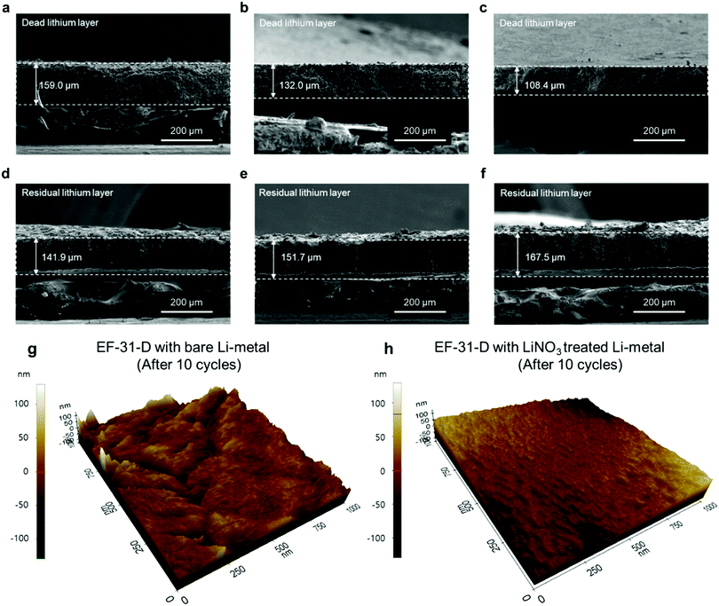
To provide better insight into the Li depositing and stripping behavior during cycling, the cycled Li–metal electrode was examined using cross-sectional SEM and AFM. To characterize the deposited and stripped Li morphologies after the 1st cycle, coin-type Li/Li half-cells with different electrolytes with/without the LiNO3-pretreated Li–metal anode were assembled. Li was deposited and stripped at 0.18 mA cm−2 (1 cycle) and the cross-section samples (deposited Li) were prepared using focused ion beam. As seen in Fig. 3f–h, Li is uniformly deposited on the entire LiNO3-pretreated anode surface. The deposited Li metal consisted of nearly-connected thick particles (average particle size: ∼10 μm) whereas the cell using bare Li produced relatively thin discrete particles. Therefore, the cross-section images of the cycled anodes are in good agreement with the plan-view SEM images of the deposited Li morphologies on the anode surface in Fig. 3c–e. In addition, the LiNO3-pretreated Li anode showed a less damaged surface without pitting after stripping than the bare Li anode did. This indicates that the Li2O-rich SEI layer created via an ex situ route could effectively improve Li reversibility during a plating–stripping process (Fig. 3i–k).31 During the repeated plating–stripping process, such densely packed and smooth Li morphology found on the LiNO3-treated Li–metal surface significantly suppressed the unwanted interfacial reaction between the electrolyte and Li–metal surface and exhibited the least amount of Li loss as a dead layer compared to the bare Li–metal (Fig. 4a–f). AFM images of the cycled Li metal surface further highlight the synergetic effect of the proposed in situ and ex situ treatments of the Li surface. The Li–metal/EF-31-D/bare Li–metal and LiNO3 treated Li–metal/EF-31-D/LiNO3 treated Li–metal cells were cycled 10 times at a current density of 0.18 mA cm−2 and disassembled.
As expected, the bare Li–metal showed a rough surface morphology whereas the LiNO3-treated Li–metal maintained a relatively uniform and smooth surface (Fig. 4g and h) even after the repeated depositing–stripping process. The observed morphology of the deposited Li unequivocally demonstrates the strikingly different effect of the LiDFOB additive in combination with LiNO3 pre-treatment of the anode, which correlates well with XPS and/or the AFM and nano-indentation analysis. The formation of a robust and high-quality SEI film on the Li–metal anode surface via the in situ and ex situ routes expedited fast Li+ ion transport, thereby facilitating the growth of Li nuclei into a densely packed large particle-like structure instead of the typical dendritic structure.32,33 The illustration in Fig. S10 (ESI†) summarizes how the LiDFOB additive and the LiNO3 pretreatment modified the chemical constituents of the SEI layer; inorganic components such as LiF, Li2CO3, Li2O, and borate complexes were formed in the SEI.
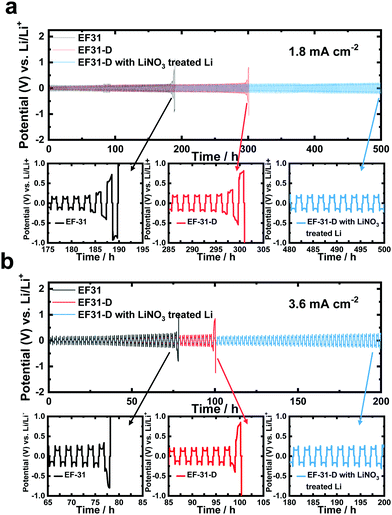
To directly verify the cycling stability of the Li–metal, galvanostatic cycling was performed using a symmetric Li/Li cell at a Li plating/stripping current density of 1.8 mA cm−2 with a cycling capacity of 1.8 mA h cm−2 (2 h per cycle) (Fig. 5a). The cell using the EF-31 electrolyte shows poor cycling stability (90 cycles) against the Li–metal. The cycling stability was improved upon using the EF-31-D electrolyte (150 cycles). The improved stability reflects the compact Li morphology and the significant improvement of the Li CE. The most dramatic improvement was observed with the Li anode pretreated with LiNO3. The cell using the EF-31-D electrolyte and the LiNO3-treated anode exhibited a lower overpotential and an outstanding long-term stability of over 500 h (250 cycles). The improvement in the cycling stability became more pronounced at a higher current density of 3.6 mA cm−2 (Fig. 5b). Cycled anodes were retrieved from the Li/Li symmetric cells after 100 cycles and characterized using SEM (Fig. 4a–f). A SEM image of the cycled Li anode using the EF-31 electrolyte shows a dead layer (159 μm) while the residual bottom active layer was only 142 μm in thickness. The untreated anode cycled in the modified EF-31-D electrolyte exhibited a relatively low consumption of Li metal compared to the cell using the EF-31 electrolyte without the additive. Expectedly, the cycled LiNO3-pretreated anode in the EF-31-D electrolyte showed the least Li loss as the dead layer thickness was limited to 108 μm while a fresh thick active Li layer with a thickness of 168 μm remained after 100 cycles, clearly verifying the effectiveness of the proposed electrolyte and anode modifications.
Fast charging of the Li/NCM battery at a practical level
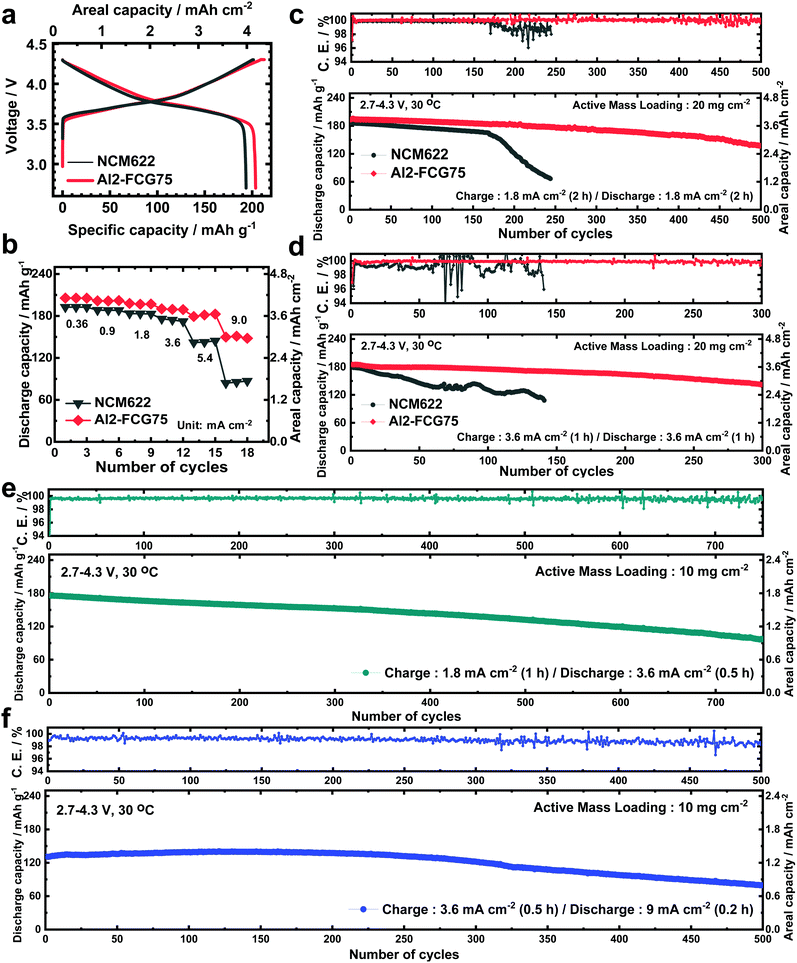
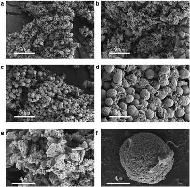
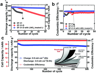
In general, a high cathode areal loading level, which is required for large-format energy storage, compromises the stability of both the cathode and anode. A high areal loading necessitates the utilization of a large amount of Li in each plating/stripping process at the anode, resulting in serious parasitic side reactions and quick build-up of the Li degradation layer.34,35 At the cathode, an increased loading level at a given current density translates into a higher cell current, which undermines the mechanical stability of the cathode through accelerated removal/insertion of Li ions, eventually shortening the lifetime of the Li/NMC battery.36 The Al2-FCG75 cathode, which is specially engineered to ensure high capacity and cycling stability,37 is an excellent candidate for a high-density LMB. To benchmark against a commercial NCM cathode, Li[Ni0.6Co0.2Mn0.2]O2 with a uniform spatial composition (NCM622) was also tested under identical conditions. Comparing the mechanical strength of the NCM622 and Al2-FCG75 secondary particles via micro-compression tests (Fig. S4, ESI†), the Al2-FCG75 particle exhibited a single-particle strength of 95.4 MPa. In comparison, the NCM622 particle had a much lower value of 50.2 MPa, attesting to the superior mechanical stability imparted by the unique microstructure of an FCG cathode. The Li/NCM622 and Li/Al2-FCG75 batteries were fabricated using LiNO3-treated Li–metal and EF-31-D electrolyte. At 0.18 mA cm−2, the Li/NCM622 and Li/Al2-FCG75 cells delivered a discharge capacity of 195 and 205 mA h g−1, respectively, corresponding to a cathode loading of 3.8 mA h cm−2 and 4.1 mA h cm−2 (Fig. 6a). The Al2-FCG75 cathode exhibited superior capacity retention compared to that of the NCM622 cathode at higher current densities. At 9.0 mA cm−2, the Al2-FCG75 cathode maintained a high discharge capacity of 150 mA h g−1 (73% of the capacity at 0.18 mA cm−2) whereas the capacity of the NCM622 cathode was limited to only 70 mA h g−1 (36% of the capacity at 0.18 mA cm−2) (Fig. 6b). As for the extended cycling, the Li/NCM622 cell exhibited good cycling stability at 1.8 mA cm−2 up to the 170th cycle with an acceptable capacity fading rate of 0.06% per cycle; however, the cell suffered from drastic capacity drop accompanied by erratic CE (Fig. 6c).To determine the cause of the sudden capacity fade, the recovered cathode and anode from the cycled cell were reassembled with fresh electrodes (LiNO3-treated Li–metal and NCM622, respectively) and EF-31-D electrolyte (Fig. S11, ESI†). The recovered Li–metal anode nearly reproduced the discharge capacity of a fresh anode at 1.8 mA cm−2. In contrast, the discharge capacity of the recovered NCM622 cathode showed 13% decrease (162 mA h g−1). This result suggests that the drastic capacity fading of the Li/NCM622 cell is likely related to the cathode failure. SEM images of the cycled NCM622 cathode (after 244 cycles) reveal that most of the secondary particles had nearly pulverized, making it difficult to recognize the initial spherical morphology prior to cycling (Fig. S1, ESI,† and Fig. 7a, b). To better demonstrate the synergetic effect of the LiDFOB additive and LiNO3 pretreatment, two Li/Al2-FCG75 cells were assembled with and without the LiDFOB additive while bypassing the LiNO3 pretreatment (Fig. S12, ESI†). The cycling behavior observed in the Li/Li symmetric cells was directly reproduced in the Li/Al2-FCG75 cells. In comparison, the Li/Al2-FCG75 cell using the LiNO3-treated anode and EF-31-D electrolyte exhibited an unprecedented cycling stability with extremely high CE (≥99.8%) up to 500 cycles at a current density of 1.8 mA cm−2 (Fig. 6c). The electrochemical impedance spectroscopy (EIS) provides further evidence (Fig. S13, ESI†) that the LiNO3-treated Li–metal/EF-31-D/Al2-FCG75 cell reduced the surface resistance and the charge transfer resistance through inhibiting the parasitic reactions. The cycling stability is corroborated by the mechanical stability of the Al2-FCG75 cathode; the spherical shape of its cycled secondary particles (after 500 cycles) was well-preserved with no significant cracking (Fig. 7c and d). A highlight of the proposed Li/Al2-FCG75 cell is that the Al2-FCG75 cathode, the pretreated Li anode, and the modified EF-31-D electrolyte were combined to produce an LMB cell capable of withstanding a high loading level (4.1 mA h cm−2) at a high current density (3.6 mA cm−2), thus simultaneously enabling the realization of high-energy density and fast charging. At 3.6 mA cm−2, the proposed Li/Al2-FCG75 cell exhibited remarkable cycling stability over 300 cycles with capacity retention of 80%, whereas the Li/NCM622 cell showed unstable cycling from the beginning, recording a continuous capacity drop (Fig. 6d). The demonstrated cycling stability of the Li/Al2-FCG75 cell at 3.6 mA cm−2 is clearly unmatched by the literature data, as shown in Scheme 1, which shows a comparison of the cycling data at 3.6 mA cm−2 with those run at areal capacities greater than 2 mA h cm−2 and current densities higher than 2 mA cm−2 using conventional NCM cathodes. To further establish the durable cycling of the Li/Al2-FCG75 cathode at fast charge–discharge current densities, we fabricated cells with a capacity loading of 2.0 mA h cm−2 and tested them under severe protocols; (i) charging at 1.8 mA cm−2 (1 h) but discharging at 3.6 mA cm−2 (0.5 h) and (ii) charging at 3.6 mA cm−2 (0.5 h) but discharging at 9 mA cm−2 (0.2 h) (Fig. 6e, f and Fig. S14a, b, ESI†). The Li/Al2-FCG75 cells showed excellent long-term cycling stability up to 750 cycles and 500 cycles, respectively, under the harsh protocols (i) and (ii). These long-term cycling stabilities unequivocally demonstrate that the choice of a suitable cathode material is as important as Li–metal protection for developing a practical LMB.
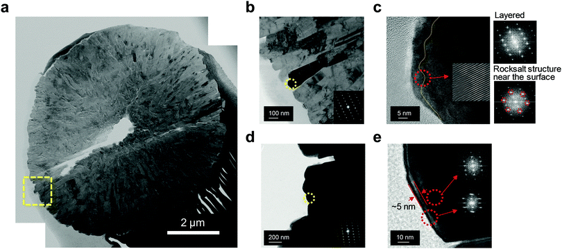
The superior structural stability of Al2-FCG75 was further verified by transmission electron microscopy (TEM). A bright-field scanning TEM image of cycled Al2-FCG75 in Fig. 8a (after 300 cycles at 3.6 mA cm−2) reveals that the secondary particle did not suffer substantial damage other than a single hairline crack (the void at the center is likely inherited from the precursor stage), which is in stark contrast with the near-pulverization of the NCM622 cathode after only 141 cycles. One of the reasons for the superior mechanical stability of Al2-FCG75 is its unique microstructure: its primary particles are spatially confined with a radial geometry (Fig. 8b), which aids the dissipation of the internal anisotropic strain caused by the phase transition of the Ni-rich NCM cathode in the deeply charged state.38 A high-resolution TEM near the surface of a primary particle indicates that the primary particle sustained the usual electrolyte attack and developed a >10 nm-thick NiO-like rock salt surface layer (Fig. 8c). The Fourier-filtered image in the inset clearly shows the transition from the layered structure to the rock salt structure through random intermixing of the transition metal ions and Li ions. TEM analysis also was carried out on the pulverized NCM622 cathode particle and a high-resolution TEM image from its surface primary particle indicates that the damaged surface layer (i.e., rock salt layer) is confined to a thickness of 5 nm (Fig. 8d and e). It appears that the NCM622 cathode did not seriously suffer from electrolyte attack, which is likely because of the relatively short cycling compared to that of the Al2-FCG75 cathode. The TEM observation of the cycled cathodes suggests that the main degradation mechanism of the cathode, especially when cycled at a high current density, is the loss of mechanical integrity arising from the internal compressive/tensile strain occurring repeatedly at a fast rate during charging and discharging. This internal strain from the anisotropic unit cell volume contraction/expansion is already well established as the main degradation mechanism for Ni-rich NCM and NCA cathodes.39 Furthermore, at a high current density, the detrimental effect is accentuated because the material cannot structurally relax because of the fast rate of Li removal and uptake. Therefore, one of the important conclusions drawn from this work is that the importance of the cathode material, especially its mechanical stability, cannot be overemphasized for future LMBs with improved Li stabilization schemes because the performance of an LMB will be eventually limited by the performance of the cathode.
Pouch-type cell
We also constructed pouch-type Li/Al2-FCG75 cells using different electrolytes with/without the pretreated Li–metal anode. Similar to the coin-type cell, a high cathode loading of 10 mg cm−2 and a 200 μm-thick Li–metal anode were used in the pouch-type cell. It was shown that the cycle life of a Li–metal battery is typically reduced to less than 20 cycles when the Li foil thickness is limited to 50 μm which is required for a practical Li metal battery due to the electrolyte and Li consumption in early cycles.40 In this work, we used a relatively thick Li foil (200 μm) because the main purpose of our study is to study the intrinsic stability of the Li metal anode and test the feasibility for developing a practical high energy density Li–metal battery. To confirm the practical applicability of the proposed concept, cycling of the pouch-type cells was performed at a high current density of 1.8 mA cm−2. Prior to regular cycling at a current density of 1.8 mA cm−2 (1C), three formation cycles were carried out at 0.18, 0.36, and 0.9 mA cm−2. As can be seen in Fig. 9a and b, the pouch-type cells showed a similar trend in cycling performance as the coin-type cell result. Furthermore, the pouch cell with the LiNO3-treated Li/EF-31-D/Al2-FCG75 cathode exhibited excellent cycling stability with a capacity retention of 90% over 500 cycles at a high current density of 0.9 mA cm−2 (charging)/3.6 mA cm−2 (discharging), clearly demonstrating the good cycling stability even at a scaled-up level, confirming the commercial viability of the proposed LMB (Fig. 9c). Lastly, from the practical standing point, we calculated the gravimetric energy density of our Li/NCM battery based on a pouch-type cell. The cell parameters of the pouch-type cell for energy density calculation are listed in Table S1 (ESI†). The N/P ratio (capacity ratio of anode to cathode) of 20 and E/C ratio (ratio of electrolyte weight over cell capacity) of 7 were used in our pouch-type cell. Other values for the cell components (i.e. Al-foil, Cu-foil, separator, packing foil, and tab) were obtained from commercialized LIBs.27 The energy density of proposed the Li/NCM battery was calculated at a 2.0 A h level. Based on these parameters, the energy density of the proposed pouch-type cell is 300 W h kg−1 at the cell level.Conclusions
In this study, we proposed a combination of cathode, anode, and electrolyte to develop an LMB capable of cycling both at a high loading capacity and at a high current density, a feat that has not been achieved with any of the previously proposed LMBs, to the best of our knowledge. In general, fast charging accelerates the deleterious dendritic growth of Li and thus aggravates the parasitic reactions between the Li–metal anode and electrolyte. The EF-31 electrolyte with LiDFOB produced an inorganic-compound-rich SEI layer that remained robust and conductive through in situ electrochemical reactions. The LiNO3 treatment of the Li–metal anode via an ex situ route added a prior Li2O-rich SEI layer, which was critical for creating a passivation film on the Li–metal surface to suppress the dendritic Li growth at a high current density. In addition, fast removal/insertion of Li ions from NCM cathodes also deteriorates the stability of the host structure. The Al2-FCG75 cathode provided the necessary cycling stability at a high loading level. Integrating these components produced an LMB that allowed a high areal capacity of 4.1 mA h cm−2 and an unprecedented cycling stability over 300 cycles at a high current density of 3.6 mA cm−2. Moreover, the scaled-up pouch-type cell assembled by these components represents excellent practical applicability, with an outstanding cycle retention of 90% over 500 cycles. Nonetheless, to compete with the energy density of the state-of-the-art Li-ion batteries, the thickness (amount) of the Li foil should be reduced while capacity loading of the cathode is further increased in Li–metal batteries. We believe that this work marks an important step in the design of an LMB to effectively stabilize the Li–metal surface. In addition, this work also re-highlights the importance of choosing an optimal cathode material in practical applications of an LMB.Author contributions
Y.-K. S. developed the original research concept and supervised the project. Y.-K. S., J.-Y. H. and S.-J. P. designed the experiments and prepared the materials. J.-Y. H. and S.-J. P. performed the electrochemical test and Li–metal surface characterization (SEM, XPS and FT-IR). C. S. Y. contributed to analyzing the TEM, AFM and Nanoindentation experiments. J.-Y. H., S.-J. P., C. S. Y. and Y.-K. S. contributed to interpretation of the results and wrote the manuscript.Conflicts of interest
There are no conflicts to declare.Acknowledgements
This work was supported by the National Research Foundation of Korea (NRF) grant funded by the Korea government Ministry of Education and Science Technology (MEST) (NRF-2018R1A2B3008794) and supported by a Human Resources Development programme (No. 20184010201720) of a Korea Institute of Energy Technology Evaluation and Planning (KETEP) grant, funded by the Ministry of Trade, Industry and Energy of the Korean government.Notes and references
- International Energy Agency. Global EV Outlook 2018: Towards cross-modal electrification (2018); https://webstore.iea.org/global-ev-outlook-2018/(accessed: December 2018).
- B. Scrosati, J. Hassoun and Y.-K. Sun, Energy Environ. Sci., 2011, 4, 3287 RSC.
- K. J. Harry, D. T. Hallinan, D. Y. Parkinson, A. A. MacDowell and N. P. Balsara, Nat. Mater., 2014, 13, 68 CrossRef PubMed.
- A. Varzi, R. Raccichini, S. Passerini and B. Scrosati, J. Mater. Chem. A, 2016, 4, 17251 RSC.
- A. Basile, A. I. Bhatt and A. P. O’Mullane, Nat. Commun., 2016, 7, 11794 CrossRef PubMed.
- H. Song, J. Liu, B. Liu, J. Wu, H.-M. Cheng and F. Kang, Joule, 2018, 2, 1 CrossRef.
- Y. Sun, Y. Zhao, J. Wang, J. Liang, C. Wang, Q. Sun, X. Lin, K. R. Adair, J. Luo, D. Wang, R. Li, M. Cai and X. Sun, Adv. Mater., 2018, 31, 1806541 CrossRef PubMed.
- J. Liang, X. Li, Y. Zaho, L. V. Goncharova, G. Wang, K. R. Adair, C. Wang, R. Li, Y. Zhu, Y. Qian, L. Zhang, R. Yang, S. Lu and X. Sun, Adv. Mater., 2018, 30, 1804684 CrossRef PubMed.
- Y. Zhao, L. V. Goncharova, Q. Sun, X. Li, A. Lushington, B. Wang, R. Li, F. Dai, M. Cai and X. Sun, Small Methods, 2018, 2, 1700417 CrossRef.
- D. Lin, Y. Liu and Y. Cui, Nat. Commun., 2017, 12, 194 CAS.
- X. Ji, K. T. Lee and L. F. Nazar, Nat. Mater., 2009, 8, 500 CrossRef CAS PubMed.
- Z. Peng, S. A. Freunberger, Y. Chen and P. G. Bruce, Science, 2012, 337, 563 CrossRef CAS PubMed.
- X.-Q. Zhang, X.-B. Cheng, X. Chen, C. Yan and Q. Zhang, Adv. Funct. Mater., 2017, 27, 1605989 CrossRef.
- G. Salitra, E. Markevich, M. Afri, Y. Talyosef, P. Hartmann, J. Kulisch, Y.-K. Sun and D. Aurbach, ACS Appl. Mater. Interfaces, 2018, 10, 19773 CrossRef CAS PubMed.
- J. Zheng, M. H. Engelhard, D. Mei, S. Jiao, B. J. Polzin, J.-G. Zhang and W. Xu, Nat. Energy, 2017, 2, 17012 CrossRef CAS.
- P. Verma, P. Maire and P. Novak, Electrochim. Acta, 2010, 55, 6332 CrossRef CAS.
- A. Xiao, L. Yang, B. L. Lucht, S.-H. Kang and D. P. Abraham, J. Electrochem. Soc., 2009, 156, A318 CrossRef CAS.
- T. Schedlbuer, U. C. Rodehorst, C. Schreiner, H. J. Gores and M. Winter, Electrochim. Acta, 2013, 107, 26 CrossRef.
- B. S. Parimalam and B. L. Lucht, J. Electrochem. Soc., 2018, 165, A251 CrossRef CAS.
- L. Xia, S. Lee, Y. Jiang, Y. Xia, G. Z. Chen and Z. Liu, ACS Omega, 2017, 2, 8741 CrossRef CAS.
- B. D. Adams, J. Zheng, X. Ren, W. Xu and J.-G. Zhang, Adv. Energy Mater., 2018, 8, 1702097 CrossRef.
- B. D. Adams, E. V. Carino, J. G. Connell, K. S. Han, R. Cao, J. Chen, J. Zheng, Q. Li, K. T. Mueller, W. A. Henderson and J.-G. Zhang, Nano Energy, 2017, 40, 607 CrossRef CAS.
- N.-W. Li, Y.-X. Yin, C.-P. Yang and Y.-G. Guo, Adv. Mater., 2016, 28, 1853 CrossRef CAS PubMed.
- J. Becking, A. Grobmeyer, M. Kolek, U. Rodehorst, S. Schulze, M. Winter, P. Bieker and M. C. Stan, Adv. Mater. Interfaces, 2017, 4, 1700166 CrossRef.
- D. J. Lee, H. Lee, Y.-J. Kim, J.-K. Park and H.-T. Kim, Adv. Mater., 2016, 28, 857 CrossRef CAS PubMed.
- S. Xiong, K. Xie, Y. Diao and X. Hong, Electrochim. Acta, 2012, 83, 78 CrossRef CAS.
- S.-J. Park, J.-Y. Hwang, C. S. Yoon, H.-G. Jung and Y.-K. Sun, ACS Appl. Mater. Interfaces, 2018, 10, 17985 CrossRef CAS PubMed.
- P. Bai, J. Li, F. R. Brushett and M. Z. Bazant, Energy Environ. Sci., 2016, 9, 3221 RSC.
- G. B. Appetecchi, G. Dautzenberg and B. Scrosati, J. Electrochem. Soc., 1996, 143, 6 CrossRef CAS.
- S. Gao, K. Wang, R. Wang, M. Jiang, J. Han, T. Gu, S. Cheng and K. Jiang, J. Mater. Chem. A, 2017, 5, 17889 RSC.
- F. Shi, A. Pei, D. T. Boyle, J. Xie, X. Yu, X. Zhang and Y. Cui, PNAS, 2018, 21, 8529 CrossRef PubMed.
- X.-B. Cheng, C. Yan, X. Chen, C. Guan, J.-Q. Huang, H.-J. Peng, R. Zhang, S.-T. Yang and Q. Zhang, Chem, 2017, 2, 258 CAS.
- X. Fan, L. Chen, O. Borodin, X. Ji, J. Chen, S. Hou, T. Deng, J. Zheng, C. Yang, S.-C. Liou, K. Amine, K. Xu and C. Wang, Nat. Nanotechnol., 2018, 13, 715 CrossRef CAS.
- S. Jiao, J. Zheng, Q. Li, X. Li, M. H. Engelhard, R. Cao, J.-G. Zhang and W. Xu, Joule, 2018, 2, 110 CrossRef CAS.
- X. Li, J. Zhang, X. Ren, M. H. Engelhard, W. Zhao, Q. Li, J.-G. Zhang and W. Xu, Adv. Energy Mater., 2018, 8, 1703022 CrossRef.
- J.-Y. Hwang, S.-T. Myung, C. S. Yoon, S.-S. Kim, D. Aurbach and Y.-K. Sun, Adv. Funct. Mater., 2016, 26, 8083 CrossRef CAS.
- Y.-K. Sun, Z. Chen, H.-J. Noh, D.-J. Lee, H.-G. Jung, Y. Ren, S. Wang, C. S. Yoon, S.-T. Myung and K. Amine, Nat. Mater., 2012, 11, 942 CrossRef CAS PubMed.
- U.-H. Kim, E.-J. Lee, C. S. Yoon, S.-T. Myung and Y.-K. Sun, Adv. Energy Mater., 2016, 6, 1601417 CrossRef.
- H.-H. Ryu, K.-J. Park, C. S. Yoon and Y.-K. Sun, Chem. Mater., 2018, 30, 1155 CrossRef CAS.
- J. Liu, et al. , Nat. Energy, 2019, 4, 180 CrossRef CAS.
Footnotes |
| † Electronic supplementary information (ESI) available. See DOI: 10.1039/c9ee00716d |
| ‡ Jang-Yeon Hwang and Seong-Jin Park equally contributed to this work. |
| This journal is © The Royal Society of Chemistry 2019 |

