Electrocoalescence of liquid marbles driven by embedded electrodes for triggering bioreactions†
Yage
Zhang
 ab,
Xiangyu
Fu
 ab,
Wei
Guo
 ab,
Yi
Deng
 ac,
Bernard P.
Binks
 d and
Ho Cheung
Shum
*ab
aDepartment of Mechanical Engineering, University of Hong Kong, Pokfulam Road, Hong Kong. E-mail: ashum@hku.hk
bHKU-Shenzhen Institute of Research and Innovation (HKU-SIRI), Shenzhen, Guangdong 518057, China
cSchool of Chemical Engineering, Sichuan University, Chengdu, 610065, China
dDepartment of Chemistry and Biochemistry, University of Hull, Hull, HU6 7RX, UK
First published on 4th September 2019
Abstract
Liquid marbles need to be controlled precisely to benefit applications, for instance, as microreactors on digital microfluidic platforms for chemical and biological assays. In this work, a strategy is introduced to coalesce liquid marbles via electrostatics, where two liquid marbles in contact can coalesce when a sufficiently high voltage is applied to embedded electrodes. With the understanding of the mechanism of coalescence through relating the electric stress and the restoring capillary pressure at the contact interface, this method coalesces liquid marbles efficiently. When compared with the existing electrocoalescence method, our approach does not require immersion of electrodes to trigger coalescence. We demonstrate this to exchange the medium for the culture of cell spheroids and to measure the cell metabolic activity through a CCK-8 assay. The manipulation of liquid marbles driven by electrostatics creates new opportunities to conduct chemical reactions and biomedical assays in these novel microreactors.
1. Introduction
Liquid droplets have been investigated as discrete and digitized microreactors in microfluidics-based applications to achieve low-cost and high-throughput detection.1,2 However, bare droplets tend to wet the contact substrate and lead to carry-over and cross-contamination.3 An approach to eliminate wetting is to coat droplets with nano-/micro-sized hydrophobic particles, often known as liquid marbles.4 Compared with bare droplets, the liquid content in the liquid marbles does not come into contact directly with external substrates, hence being free of cross-contamination, and the particle layer also enhances marble robustness and reduces evaporation.5–7 Coating particles that encapsulate the liquid droplet not only stabilize the liquid–air interface, but also catalyse the subsequent biological or chemical reactions.8–11 Liquid marbles have also been applied for blood typing,12 water pollution detection,13 gas sensing,14,15 drug delivery16,17 and culture of tumour and cell spheroids.18–21Despite the promise of liquid marbles as microreactors on digital microfluidic platforms, their applications require exquisite control of multiple marbles. To this end, various methods have been applied to coalesce liquid marbles controllably by introducing external fields, including gravitational, acoustic and magnetic fields.22 For example, vertical collision of liquid marbles has been found to induce their coalescence upon impact,23,24 or by accelerating liquid marbles via rolling to gain kinetic energy.25 Liquid marbles can also be manipulated to coalesce via acoustic levitation.26,27 However, these approaches require complex peripheral instruments such as a high voltage converter and acoustic levitator, as well as tedious manual work. Hydrophobic magnetic particles have also been used to control the coalescence of liquid marbles,28–31 though it is only limited to marbles coated with magnetic particles. Alternatively, the coalescence of liquid marbles can be induced via electrostatics. For instance, two liquid marbles can be coalesced by applying a DC voltage through electrodes that are directly immersed in them.32,33 The electrocoalescence of marbles is robust and controllable, but the direct contact of the electrodes with different marbles can result in cross-contamination and destabilization of marble microreactors. Furthermore, electrolysis can be triggered and limit the applicability of the method (Fig. S1a†).33 Therefore, a robust and general electrocoalescence approach for marble microreactors without immersion of electrodes is urgently needed.
In this work, we propose a facile strategy to coalesce liquid marbles with non-immersed electrodes by embedding electrode plates under a dielectric layer. This approach can avoid the problem of severe electrolysis, even if the coalesced marble is charged with a high voltage for several minutes after coalescence (Fig. S1b†). This approach is general for coalescing liquid marbles coated with particles of sizes ranging from hundreds of nanometers to a few tens of micrometers. While marbles coated with micron-sized particles are deformed during coalescence, nanoparticle-coated marbles retain their spherical shape. As the maintenance of shape can facilitate further marble manipulation, we focus on nanoparticle-coated liquid marbles in this work. The electrocoalescence of these marbles occurs only above a critical voltage. The critical voltage depends significantly on the size of the stabilizing particles, the surface tension of the encapsulated liquid and the thickness of the dielectric layer. The dependence can be explained by balancing the electric stress and capillary pressure. Moreover, the electrical conductivity of the aqueous droplet also affects the critical voltage. This effect is attributed to the non-negligible electric double-layer capacitance induced in nanoparticle-coated liquid marbles. Finally, we perform a cell metabolic activity assay based on this approach, highlighting its potential for biomedical analysis.
2. Experimental section
2.1. Materials
Liquid marbles were prepared by depositing aqueous droplets on a hydrophobic particle bed. Coating particles included PTFE grains (diameter = 35 μm, particle–water contact angle = 110°, Sigma-Aldrich, USA), silicone resin particles (diameter = 2.0 μm, 6.0 μm or 12.0 μm, particle–water contact angle = 91°, Momentive Performance Material Inc., Japan), silicone particles (diameter = 5.0 μm, NanoMicro Tech. Inc., China) and silica nanoparticles (primary diameter = 7 nm, particle–water contact angle = 118°, Aerosil R812, Evonik, Germany). Deionized (DI) water (Direct-Q, Merck Millipore, Germany) was used for most experiments, unless otherwise stated. The surface tension of the liquid phase γ was varied by dissolving sodium dodecyl sulfate (Aladdin, China) in DI water at different concentrations. The values of the surface tension were measured using the pendant-drop method.34,35 The viscosity of the liquid η was changed by dissolving dextran (Pharmacosmos, Denmark) in DI water at different weight fractions, and the value was measured using a microfluidic viscometer (microVISC, Rheosense Inc.). Sodium chloride (99.5%, Sigma-Aldrich) was added to DI water at different concentrations to vary the electrical conductivity κ of the liquid, and the conductivity was measured using an electrical conductivity meter (CyberScan COND 610, Eutech Inc). The dielectric layer was prepared by mixing poly(dimethylsiloxane) (PDMS) and a curing agent (Dow Corning, USA) at a weight ratio of 10![[thin space (1/6-em)]](https://www.rsc.org/images/entities/char_2009.gif) :
:![[thin space (1/6-em)]](https://www.rsc.org/images/entities/char_2009.gif) 1. The thickness of the dielectric layer was manipulated by adjusting the rotation speed of the spin coater (WS-650MZ-23NPPB, Laurell) and measured using a profilometer (DektakXT, Bruker). Human bone marrow-derived mesenchymal stem cells (hBMSCs) were purchased from American Type Culture Collection (ATCC, PCS-500-012, VA, USA). Dulbecco's modified Eagle medium (DMEM), Hanks' balanced salt solution (HBSS), fetal bovine serum (FBS), 0.25% Trypsin-EDTA, and 100× penicillin and streptomycin were purchased from Gibco (Grand Island, NY, USA). We prepared the culture medium by adding 10% (v/v) FBS and 1% (v/v) penicillin and streptomycin into fresh DMEM. A cell counting kit-8 (CCK-8) was bought from KeyGEN BioTECH, China. Centrifugation was performed in a Thermo Scientific Sorvall ST 8R centrifuge, adapted with a HIGHConic III rotor.
1. The thickness of the dielectric layer was manipulated by adjusting the rotation speed of the spin coater (WS-650MZ-23NPPB, Laurell) and measured using a profilometer (DektakXT, Bruker). Human bone marrow-derived mesenchymal stem cells (hBMSCs) were purchased from American Type Culture Collection (ATCC, PCS-500-012, VA, USA). Dulbecco's modified Eagle medium (DMEM), Hanks' balanced salt solution (HBSS), fetal bovine serum (FBS), 0.25% Trypsin-EDTA, and 100× penicillin and streptomycin were purchased from Gibco (Grand Island, NY, USA). We prepared the culture medium by adding 10% (v/v) FBS and 1% (v/v) penicillin and streptomycin into fresh DMEM. A cell counting kit-8 (CCK-8) was bought from KeyGEN BioTECH, China. Centrifugation was performed in a Thermo Scientific Sorvall ST 8R centrifuge, adapted with a HIGHConic III rotor.
2.2. Experimental setup
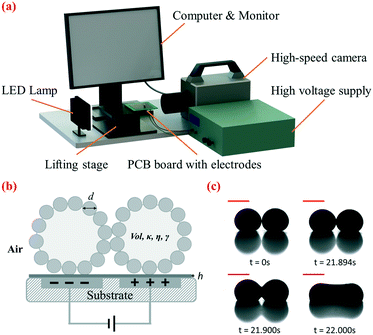
The setup for electrocoalescence of liquid marbles comprised a lifting platform, an open-source printed circuit board (PCB) design which incorporated embedded electrodes covered by a PDMS dielectric layer, a high-voltage supply, a LED lamp, a high-speed camera and a computer monitor (Fig. 1a). Two neighbouring electrodes on the open-source digital microfluidic design (OpenDrop V2, Gaudi Lab) were applied as embedded electrodes, and the whole design was fabricated by common PCB protocols. A dielectric layer made of PDMS was deposited on top of the electrodes, and two metal wires were soldered to the two selected electrodes at the backside of the PCB. The PCB was fixed to the lifting platform using double-sided tape. The high DC voltage supply was then connected to the electrodes. A high-speed camera (Photron Fastcam SA3) was used to record the side view of the coalescence of liquid marbles. Recorded videos and images were viewed using the camera software Photron Fastcam Viewer (PFV) and then analyzed using ImageJ (National Institutes of Health, USA).2.3. Preparation of liquid marbles
To prepare liquid marbles, a pipette (Eppendorf Research plus) was used to deposit liquid droplets onto a plastic culture dish covered by a layer of nano- or micro-sized particles. The volume Vol of the liquid marble for testing (unless otherwise stated) was 10 μL. Slight tilting and gentle rolling of the dish caused the droplet to become coated with particles. After formation, two liquid marbles were transported to the platform from the particle bed using a plastic spoon. Liquid marbles were placed on top of two adjacent electrodes and pushed to come into contact with each other using a rod treated with hydrophobic silane for the coalescence experiment.2.4. Electrocoalescence of liquid marbles driven by embedded electrodes
Two metal wires were soldered to connect the embedded electrodes to the DC voltage supply (Tianjin Dongwen, China). The voltage was increased gradually until two liquid marbles coalesced. In the meantime, the high-speed camera recorded the lateral-view morphology of the liquid marbles at a frame rate of 3600 fps (unless otherwise stated). All experiments described were performed at room temperature (∼25 °C) and at a relative humidity of 55%. The experiments were repeated at least 15 times to determine the average critical voltage.2.5. Cell-containing liquid marble preparation and stem cell spheroid culture in microreactors
hBMSCs were cultured in a common cell culture dish. When hBMSCs were cultured to 70–80% confluency, the cells were washed with HBSS buffer saline and dispersed into single cells by injecting 3 mL of 0.25% Trypsin and incubating for 3 min. 3 mL of DMEM medium was then injected into the culture dish to neutralize the Trypsin. After centrifuging the collected medium with suspended cells at 1500 rpm/301.9g for 4 min, the supernatant was sucked out and replaced with fresh DMEM basal medium. Liquid marbles with a volume of 50 μL containing suspended cells at a density of 150 cells per μL were then fabricated by applying the liquid marble preparation method described above, and cultured in a humidified 5% CO2 atmosphere at 37 °C. 10 μL liquid marbles containing DMEM were merged with the liquid marble microreactors via electrocoalescence every other day to provide cells with adequate nutrition.2.6. Bioapplications in liquid marbles triggered by electrocoalescence
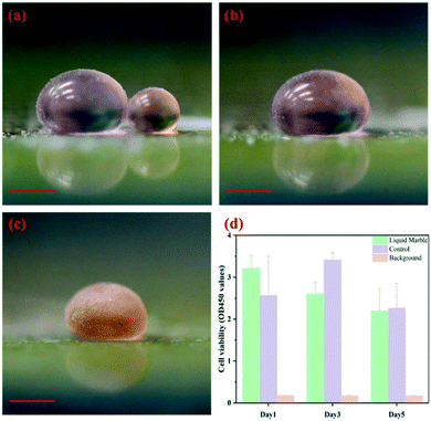
The CCK-8 assay was performed on days 1, 3 and 5 of incubation, triggered by coalescing the cell-containing liquid marble with another 10 μL liquid marble containing CCK-8 reagents (Keygen Biotech, China). The marble after coalescence was then incubated inside a 1.5 mL centrifugal tube in a humidified 5% CO2 atmosphere at 37 °C for 3 h. Digital photographs of the liquid marbles were captured before coalescence, right after coalescence and after 3 h of incubation. A quantitative CCK-8 assay was performed by transferring 50 μL of coloured mixture from liquid marble microreactors into a well of a 96-well microplate. Another 50 μL DMEM medium was then injected into each well for dilution, resulting in a final volume of 100 μL per well. The intensity of the solution was measured using a microplate reader (SpectraMax iD3, Molecular Devices), based on a colorimetric method with an excitation wavelength of 450 nm. A control group was prepared to culture hBMSCs inside a 96-well microplate, and a background which was bulk DMEM medium was introduced when hBMSCs were cultured in silica nanoparticle-based liquid marble microreactors.3. Results and discussion
3.1. Electrocoalescence of liquid marbles
In our approach, two liquid marbles are placed in contact with each other on a dielectric layer, with two adjacent electrode plates embedded beneath them (Fig. 1b). Hydrophobic particle shells separate encapsulated liquid droplets and prevent coalescence when no voltage is applied, as shown in Fig. 1c at 0 s. We gradually increase the DC voltage applied to the embedded electrodes until coalescence occurs. We increase the DC voltage manually at an average rate of 20 volts per second. The ramp rate has been shown to demonstrate a limited effect on the critical voltage (Table S1†). When the applied voltage is small, two liquid marbles attract each other as encapsulated droplets tend to merge under polarization. Their contact interface flattens but does not lead to coalescence, due to the elasticity of the particle shell (Fig. 1c, 21.894 s). Once the voltage applied exceeds a critical value Uc, coalescence is initiated at the contact interface, indicated by the sudden expansion and continuous widening of the liquid bridge (Fig. 1c, 21.900 s). Finally, the liquid bridge stops expanding and the liquid marbles merge into a dumb-bell-shaped marble as shown in Fig. 1c, at 22.000 s. The coalescence takes place within around 100 ms. Based on our experiments, electrocoalescence takes place only when the voltage reaches Uc. Holding a voltage below Uc for a longer period of time does not lead to coalescence.We have applied this approach to liquid marbles covered by particles of various sizes shown in Table S2.† This immersion-free electro-driven approach can induce coalescence not only for microparticle-coated liquid marbles but also for nanoparticle-coated ones. The versatility of this approach with respect to the particle size is highlighted and cannot be matched by that of the previous electrostatics-driven method.
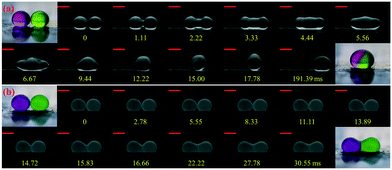
In the immersion-free electrocoalescence of liquid marbles, the shape of the liquid marble after coalescence varies with the size of the coating particles. We selected liquid marbles coated with nano-/microparticles which exhibit similar effective surface tension (shown in Fig. S2 and Table S3†). The coalescence of nanoparticle-coated marbles is very similar to that of bare droplets, where the Laplace pressure gradient governs the fluid exchange by reducing the interfacial area, and ends up with a merged marble with a quasi-spherical shape (Fig. 2a).36,37 During the collision, excess nanoparticles are found to detach from the liquid interface (video S1†). However, such a phenomenon is seldom observed for electrocoalescence of liquid marbles coated with microparticles on this platform. Two microparticle-coated liquid marbles coalesce into a dumb-bell-shaped marble (Fig. 2b), with visible particles jamming at the neck region of the merged marble (video S2†). This can be attributed to the strong desorption energy of these particles, which is ∼2 × 10⁹ kT from the air–water interface (E = πRParticle2γ(1 ± cos![[thin space (1/6-em)]](https://www.rsc.org/images/entities/char_2009.gif) θ)2, γ = 73 mN m−1) for 6 μm silicone resin particles with a contact angle of 91°, which is three to four orders of magnitude larger than that for the nanoparticles.38
θ)2, γ = 73 mN m−1) for 6 μm silicone resin particles with a contact angle of 91°, which is three to four orders of magnitude larger than that for the nanoparticles.38
The shape difference becomes more distinct when multiple liquid marbles are coalesced, as shown in Fig. S3.† Regardless of the number of liquid marbles before coalescence, nanoparticle-coated liquid marbles always merge into one spherical marble. For microparticle-coated liquid marbles, the shape after coalescence becomes more irregular with multi-particle jammed regions. The jammed particles lead to a loss of interfacial mobility of the merged liquid marble, hampering further manipulation. Among all types of particles, the ability to maintain their shape after coalescence renders nanoparticle-coated liquid marbles easily manipulated using this electro-driven approach.
3.2. Influence of different physical parameters on the critical coalescence voltage Uc
We select nanoparticle-coated liquid marbles to investigate the influence of different parameters on electrocoalescence. We first change the volume Vol and the viscosity η of the interior droplet. For liquid marbles with droplet volumes ranging from 5 μL to 20 μL (Fig. 3a), the critical voltage Uc remains roughly constant. By modulating the concentration of dextran dissolved in water from 1 wt% to 20 wt%, the viscosity changes from 1.82 mPa s to 80.24 mPa s; nonetheless, the critical voltage Uc remains roughly the same (Fig. 3b).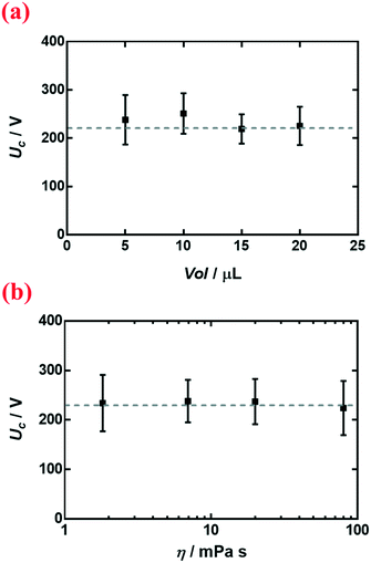 | ||
| Fig. 3 Variation of critical voltage Uc with (a) volume Vol of the liquid marble and (b) viscosity η of the encapsulated droplet. Liquid marbles were coated with R812 silica nanoparticles. | ||
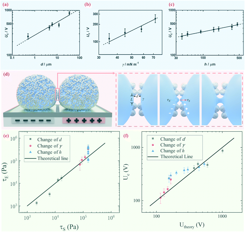
We further demonstrate however that the critical voltage Uc depends significantly on the diameter of the coating particles d, the surface tension of the encapsulated droplet γ and the thickness of the dielectric layer h. We notice that other than particle size d, materials with different properties may affect the electrical response, such as the dielectric constant and particle shape.39 To be specific, we measure the critical voltage Uc of liquid marbles coated with silica, silicone resin and PTFE particles of various sizes while similar surface tension is maintained. Both silica, silicone resin and PTFE have dielectric constants within the range of 2.1 to 5.0; and all particles are spherical. The result indicates that Uc increases significantly when the particle diameter d increases, as shown in Fig. 4a. The surface tension γ of the encapsulated droplet is changed by adding an SDS surfactant from 0.001 M to 0.008 M in 0.1 M NaCl aqueous solution. The electrical conductivity of the 0.1 M NaCl aqueous droplet is kept in the range of 761.0 μS cm−1 to 786.6 μS cm−1 by adding SDS of different concentrations, while the surface tension is decreased from 75.45 mN m−1 to 35.24 mN m−1. Thus, surface tension γ is considered the only variable in this set of experiments. Liquid marbles tend to coalesce more readily at lower surface tension (Fig. 4b). The critical voltage Uc also depends on the thickness of the dielectric layer h; an increase in h leads to an increase in Uc (Fig. 4c).
As the droplet content is electrically conductive, we assume that there is no voltage drop inside the droplet. We then construct a physical model to explain the dependence of the critical voltage Uc on the physical quantities. Referring to recent studies in the electrostatics-driven coalescence of Pickering emulsions40 and liquid marbles,32 we analyze the stresses applied on the interface where two liquid marbles are in contact. When a voltage difference is applied across the embedded electrodes, the encapsulated droplets become polarized and exert local charge. The local charge would induce electric stress τE ∼ ε0εrEloc2 towards the opposing liquid interface, where ε0εr is the relative permittivity of air and Eloc is the local electric field strength. The opposing interface will be deformed accordingly, followed by the formation of a conical tip from defects that exist on the interface with size L. The capillary pressure  resists the tip formation due to surface tension effects. Liquid marbles are expected to coalesce only when the applied voltage reaches a critical value and exerts sufficient electric stress to overcome the capillary pressure. To confirm this, as shown in Fig. 4e, we calculated and plotted the electrical stress τE as the y-axis and the capillary pressure τS as the x-axis for all systems in Fig. 4a–c (the derivation of Eloc is shown in the ESI†). Previous work on Pickering emulsions has indicated that coalescence would occur when defects at the interface have sizes similar to the particle diameter.40 Defects with sizes of the same scale as particles are also shown in Fig. S4.† Therefore, by approximating L ∼ d, the capillary pressure can be evaluated from
  . We further derive a theoretical voltage Utheory that leads to coalescence of liquid marbles based on our model (derivation can be found in the ESI†). The result has been plotted against the experimental data in Fig. 4f. The excellent agreement confirms that coalescence is triggered by liquid interface deformation driven by electrostatics.
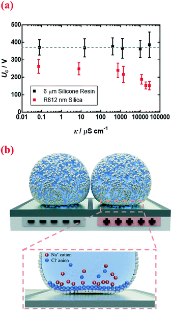
Other than physical quantities directly affecting stresses, Uc also depends on the electrical conductivity κ of the encapsulated droplet. The conductivity changes from 0.070 μS cm−1 to 29![[thin space (1/6-em)]](https://www.rsc.org/images/entities/char_2009.gif) 500 μS cm−1 when the concentration of sodium chloride dissolved in deionized water is changed from 0 M to 5 M. By increasing the electrical conductivity κ of the encapsulated electrolytic droplet, a lower voltage is needed to trigger the coalescence (Fig. 5a, nm silica). Interestingly, this effect only applies to nanoparticle-coated liquid marbles; for those coated with microparticles, the increment in conductivity tends to have a negligible impact (Fig. 5a, 6 μm silicone resin).
500 μS cm−1 when the concentration of sodium chloride dissolved in deionized water is changed from 0 M to 5 M. By increasing the electrical conductivity κ of the encapsulated electrolytic droplet, a lower voltage is needed to trigger the coalescence (Fig. 5a, nm silica). Interestingly, this effect only applies to nanoparticle-coated liquid marbles; for those coated with microparticles, the increment in conductivity tends to have a negligible impact (Fig. 5a, 6 μm silicone resin).
A likely mechanism to explain the effect of electrical conductivity on Uc is the responsive capacitance from the electric double-layer (EDL) on the particle shell surface when a liquid marble is exposed to an electric field. The structure of the induced double-layer is shown in Fig. 5b. As the concentrated electrolyte dissolves in the droplet, by assuming that there is no voltage difference across the droplet, the corresponding model for the liquid marble is proposed in Fig. S5.† The equivalent capacitance  would be the sum of the electrical double-layer capacitance CEDL cascaded with the capacitance of the particle shell CP1 that is in contact with the dielectric layer. The equivalent capacitance
  reads
reads
 | (1) |
To explain the unexpected tendency qualitatively, we apply the widely accepted Gouy–Chapman–Stern (GCS) model.41 The GCS model characterizes the EDL as a Stern layer with a finite thickness and a diffuse layer with Debye length λD. The thickness of the Stern layer at a charged interface would be compressed and respond with a higher capacitance when the electrolyte concentration is increased.41 A similar situation also applies to the diffuse layer with thickness λdiff ∼ λD. Therefore, the effective double layer becomes thinner at a higher electrolyte concentration and induces a larger capacitance CEDL. By assuming that the capacitance of the particle shell is unchanged, the cascaded capacitance  would increase accordingly. Referring to eqn (6) in the ESI,† we could derive an increment in the capacitive voltage dividing parameter β, which indicates that a smaller Uc is needed to reach the critical Eloc to overcome the restoring capillary pressure. This agrees well with the trend observed in our experiments.
Therefore, this electric double-layer capacitance only takes effect when the particle layer is thin. As for nanoparticle-coated liquid marbles, the primary diameter of silica nanoparticles is 7 nm and a few hundred nanometers for particle aggregates, the specific capacitance of the particle shell would be around ∼10−5 F m−2. The resultant capacitance of the particle layer for microparticle-based liquid marbles drops to ∼10−6 F m−2. As no obvious influence towards the critical voltage is observed, the equivalent capacitance  for microparticle-based liquid marbles is not expected to differ significantly from the original CP1. The value of the electric double-layer capacitance CEDL is expected to be within the range of 10−6 F m−2 and 10−5 F m−2.
3.3. Biomedical applications in liquid marbles triggered by electrocoalescence
Liquid marbles acting as microreactors have great potential for applications. To realize their potential, robust and efficient methodologies to coalesce and trigger the proposed microreactors without agitating the encapsulated droplets are critical. In our previous work, charging the encapsulated droplets can trigger coalescence32 but the requirement of direct immersion of electrodes in the marbles also limits their applicability to viscous glycerol solution-containing chemical reactions.33It should be noted that cell lysis would still be induced if the electrostatic field applied is sufficiently high.42,43 However, electrocoalescence driven by embedded electrodes can avoid the electrolysis problem which often interferes with the target reactions, for instance, to assay cell viability. As a demonstration, two liquid marbles containing either human bone mesenchymal stem cells (hBMSCs) or CCK-8 reagent water-soluble tetrazolium salt (WST-8) with a volume of 50 μL and 10 μL, respectively, are prepared as shown in Fig. 6a. By increasing the voltage to a critical value, the liquid marbles coalesce (Fig. 6b). After incubation for three hours, the colour change in the coalesced marble suggests that cells remain alive after the electrostatics-driven coalescence (Fig. 6c). The quantitative data of cell viability show no significant difference in cell viability after five days of culture of cells in a liquid marble microreactor and in the traditional 2D microplate (Fig. 6d). The electrostatics-driven approach also shows no effect towards the morphology of cell aggregation structures throughout the process, as indicated by the formation of a spheroid after culturing in a liquid marble microreactor (Fig. S6†).
Overall, the immersion-free electrocoalescence provides a promising strategy for studying the physical/chemical processes in liquid marbles. The ability to address individual liquid marbles without immersing electrodes in them extends the potential of existing applications towards digital liquid-marble-based microfluidics.44–46 Moreover, it represents an important advancement that allows more sophisticated chemical or biochemical reactions triggered by merging of multiple liquid marbles containing different reagents. Our results also confirm that electrocoalescence-based manipulation is compatible with cell studies, highlighting its suitability for bioreactions in liquid marble microreactors.
Conclusions
In this study, we have developed a robust method to coalesce liquid marbles in an immersion-free, electro-driven approach. We have overcome the need to immerse electrodes in the marbles. By utilizing electrostatics applied on embedded electrodes coated with a dielectric layer, two liquid marbles can coalesce when a critical voltage is applied. Based on liquid marbles coated with nanoparticles, electrocoalescence can be reliably induced by applying a voltage to overcome the capillary pressure by an electric stress. The electrical conductivity of the encapsulated droplet, which is often believed to have no impact, is also observed to affect the critical voltage. We attribute this phenomenon to the non-negligible double-layer capacitance induced from the highly concentrated electrolyte under an electric field. Finally, we confirm the potential to trigger microreactions in liquid marbles using our immersion-free electrocoalescence approach by measuring cell metabolic activities. Our understanding of electrocoalescence of liquid marbles via embedded electrodes in a dielectric layer is essential for manipulating large numbers of liquid marble microreactors for chemical and biological assays in an automated manner.Author contributions
Y. Zhang and X. Fu proposed the idea. Y. Zhang developed and conducted the majority of the experiments and prepared the original draft. Y. Zhang and W. Guo created the model. Y. Deng helped with the biomedical investigation. B. P. Binks and H. C. Shum reviewed and edited the original draft. H. C. Shum supervised the project. All authors read and approved the final manuscript.Conflicts of interest
The authors state that there are no conflicts to declare.Acknowledgements
We thank Prof. Huisheng Zhang, Dr. Zhou Liu, Dr. Tiantian Kong and Dr. Yuan Liu for their helpful discussions. We thank Mr. Hao Lyv for providing human mesenchymal stem cells. This research was supported by the General Research Fund (No. 17304514, 17306315, 17304017 and 17329516) from the Research Grants Council of Hong Kong, the Seed Fund for Basic Research (No. 201711159249, 201611159205 and 201511159280), the Seed Fund for Translational and Applied Research (No. 201711160016) from the University of Hong Kong and the Sichuan Science and Technology Program (2018JZ0026).References
- G. M. Whitesides, Nature, 2006, 442, 368–373 CrossRef CAS PubMed.
- K. Choi, A. H. Ng, R. Fobel and A. R. Wheeler, Annu. Rev. Anal. Chem., 2012, 5, 413–440 CrossRef CAS PubMed.
- D. R. Link, E. Grasland-Mongrain, A. Duri, F. Sarrazin, Z. Cheng, G. Cristobal, M. Marquez and D. A. Weitz, Angew. Chem., Int. Ed., 2006, 45, 2556–2560 CrossRef CAS PubMed.
- P. Aussillous and D. Quéré, Nature, 2001, 411, 924–927 CrossRef CAS PubMed.
- M. Dandan and H. Y. Erbil, Langmuir, 2009, 25, 8362–8367 CrossRef CAS PubMed.
- C. Fullarton, T. C. Draper, N. Phillips, R. Mayne, B. P. J. de Lacy Costello and A. Adamatzky, Langmuir, 2018, 34, 2573–2580 CrossRef CAS PubMed.
- Z. Liu, Y. Zhang, C. Chen, T. Yang, J. Wang, L. Guo, P. Liu and T. Kong, Small, 2018, 15, 1804549 CrossRef PubMed.
- Y. Sheng, G. Sun, J. Wu, G. Ma and T. Ngai, Angew. Chem., Int. Ed., 2015, 54, 7012–7017 CrossRef CAS PubMed.
- Y. E. Miao, H. K. Lee, W. S. Chew, I. Y. Phang, T. Liu and X. Y. Ling, Chem. Commun., 2014, 50, 5923–5926 RSC.
- W. Gao, H. K. Lee, J. Hobley, T. Liu, I. Y. Phang and X. Y. Ling, Angew. Chem., Int. Ed., 2015, 54, 3993–3996 CrossRef CAS PubMed.
- D. Wang, L. Zhu, J. F. Chen and L. Dai, Angew. Chem., Int. Ed., 2016, 55, 10795–10799 CrossRef CAS PubMed.
- T. Arbatan, L. Li, J. Tian and W. Shen, Adv. Healthcare Mater., 2012, 1, 80–83 CrossRef CAS PubMed.
- E. Bormashenko and A. Musin, Appl. Surf. Sci., 2009, 255, 6429–6431 CrossRef CAS.
- J. Tian, T. Arbatan, X. Li and W. Shen, Chem. Commun., 2010, 46, 4734–4736 RSC.
- J. Tian, T. Arbatan, X. Li and W. Shen, Chem. Eng. J., 2010, 165, 347–353 CrossRef CAS.
- M. Paven, H. Mayama, T. Sekido, H. J. Butt, Y. Nakamura and S. Fujii, Adv. Funct. Mater., 2016, 26, 3199–3206 CrossRef CAS.
- H. Kawashima, M. Paven, H. Mayama, H. J. Butt, Y. Nakamura and S. Fujii, ACS Appl. Mater. Interfaces, 2017, 9, 33351–33359 CrossRef CAS PubMed.
- T. Arbatan, A. Al-Abboodi, F. Sarvi, P. P. Chan and W. Shen, Adv. Healthcare Mater., 2012, 1, 467–469 CrossRef CAS PubMed.
- R. K. Vadivelu, C. H. Ooi, R.-Q. Yao, J. Tello Velasquez, E. Pastrana, J. Diaz-Nido, F. Lim, J. A. Ekberg, N. T. Nguyen and J. A. St John, Sci. Rep., 2015, 5, 15083 CrossRef CAS PubMed.
- R. K. Vadivelu, H. Kamble, A. Munaz and N. T. Nguyen, Sci. Rep., 2017, 7, 12388 CrossRef PubMed.
- H. Li, P. Liu, G. Kaur, X. Yao and M. Yang, Adv. Healthcare Mater., 2017, 6, 1700185 CrossRef PubMed.
- J. Jin, C. H. Ooi, D. V. Dao and N. T. Nguyen, Micromachines, 2017, 8, 336 CrossRef PubMed.
- J. Jin, C. H. Ooi, D. V. Dao and N. T. Nguyen, Soft Matter, 2018, 14, 4160–4168 RSC.
- C. Planchette, A.-L. Biance, O. Pitois and E. Lorenceau, Phys. Fluids, 2013, 25, 042104 CrossRef.
- T. C. Draper, C. Fullarton, R. Mayne, N. Phillips, G. E. Canciani, B. P. J. de Lacy Costello and A. Adamatzky, Soft Matter, 2019, 15, 3541–3551 RSC.
- D. Zang, J. Li, Z. Chen, Z. Zhai, X. Geng and B. P. Binks, Langmuir, 2015, 31, 11502–11507 CrossRef CAS PubMed.
- Z. Chen, D. Zang, L. Zhao, M. Qu, X. Li, X. Li, L. Li and X. Geng, Langmuir, 2017, 33, 6232–6239 CrossRef CAS PubMed.
- Y. Zhao, J. Fang, H. Wang, X. Wang and T. Lin, Adv. Mater., 2010, 22, 707–710 CrossRef CAS PubMed.
- L. Zhang, D. Cha and P. Wang, Adv. Mater., 2012, 24, 4756–4760 CrossRef CAS PubMed.
- Y. Zhao, Z. Xu, H. Niu, X. Wang and T. Lin, Adv. Funct. Mater., 2015, 25, 437–444 CrossRef CAS.
- Y. Zhao, H. Gu, Z. Xie, H. C. Shum, B. Wang and Z. Gu, J. Am. Chem. Soc., 2013, 135, 54–57 CrossRef CAS PubMed.
- Z. Liu, X. Fu, B. P. Binks and H. C. Shum, Soft Matter, 2016, 13, 119–124 RSC.
- Z. Liu, T. Yang, Y. Huang, Y. Liu, L. Chen, L. Deng, H. C. Shum and T. Kong, Adv. Funct. Mater., 2019, 29, 1901101 CrossRef.
- B. Song and J. Springer, J. Colloid Interface Sci., 1996, 184, 64–76 CAS.
- B. Song and J. Springer, J. Colloid Interface Sci., 1996, 184, 77–91 CAS.
- D. G. A. L. Aarts, H. N. W. Lekkerkerker, H. Guo, G. H. Wegdam and D. Bonn, Phys. Rev. Lett., 2005, 95, 164503 CrossRef PubMed.
- Y. Nam, H. Kim and S. Shin, Appl. Phys. Lett., 2013, 103, 161601 CrossRef.
- E. Bormashenko, Y. Bormashenko, R. Pogreb and O. Gendelman, Langmuir, 2011, 27, 7–10 CrossRef CAS PubMed.
- C.-C. Chang, C.-J. Wu, Y.-J. Sheng and H.-K. Tsao, Soft Matter, 2015, 11, 4469–4475 RSC.
- G. Chen, P. Tan, S. Chen, J. Huang, W. Wen and L. Xu, Phys. Rev. Lett., 2013, 110, 064502 CrossRef PubMed.
- M. A. Brown, A. Goel and Z. Abbas, Angew. Chem., Int. Ed., 2016, 55, 3790–3794 CrossRef CAS PubMed.
- H.-Y. Wang and C. Lu, Chem. Commun., 2006, 3528–3530 RSC.
- H.-Y. Wang, A. K. Bhunia and C. Lu, Biosens. Bioelectron., 2006, 22, 582–588 CrossRef CAS PubMed.
- X. Fu, Y. Zhang, H. Yuan, B. P. Binks and H. C. Shum, ACS Appl. Mater. Interfaces, 2018, 10, 34822–34827 CrossRef CAS PubMed.
- M. I. Newton, D. L. Herbertson, S. J. Elliott, N. J. Shirtcliffe and G. McHale, J. Phys. D: Appl. Phys., 2007, 40, 20–24 CrossRef CAS.
- G. McHale, D. L. Herbertson, S. J. Elliott, N. J. Shirtcliffe and M. I. Newton, Langmuir, 2007, 23, 918–924 CrossRef CAS PubMed.
Footnote |
| † Electronic supplementary information (ESI) available: (1) Correlation between the theoretical critical voltage and various physical parameters. (2) Sample videos for liquid marbles coated with particles of different sizes. See DOI: 10.1039/c9lc00722a |
| This journal is © The Royal Society of Chemistry 2019 |

