 Open Access Article
In situ formation and superior lithium storage properties of tentacle-like ZnO@NC@CNTs composites†
Ying
Wang
 a,
Shijia
Fan
a,
Fang
Liao
a,
Xinshi
Zheng
a,
Zhenguo
Huang
d,
Yijing
Wang
a,
Shijia
Fan
a,
Fang
Liao
a,
Xinshi
Zheng
a,
Zhenguo
Huang
d,
Yijing
Wang
 *b and
Xiaopeng
Han
 *bc
*bc
aSchool of Chemistry & Materials Science, Jiangsu Key Laboratory of Green Synthetic Chemistry for Functional Materials, Jiangsu Normal University, Xuzhou, Jiangsu 221116, China
bKey Laboratory of Advanced Energy Materials Chemistry (MOE), College of Chemistry, Nankai University, Tianjin 300071, China. E-mail: wangyj@nankai.edu.cn
cSchool of Materials Science and Engineering, Tianjin Key Laboratory of Composite and Functional Materials, Tianjin University, Tianjin 300072, China. E-mail: xphan@tju.edu.cn
dSchool of Civil & Environmental Engineering, University of Technology Sydney, NSW 2007, Australia
First published on 4th January 2019
Abstract
As a typical conversion-type electrode, ZnO has high theoretical Li+ storage capacity and is low cost. However, its practical application is far away due to its limited rate performance and cycle stability. Herein, a novel structure of double carbon coated tentacle-like ZnO composite has been synthesized, which features in situ grown carbon nanotubes (CNTs) embedded in yolk–shell polyhedra, consisting of nitrogen-doped carbon layer (NC) coated ZnO nanoparticles (ZnO@NC@CNTs). Excellent rate performance and good cycling stability are observed in the obtained ZnO@NC@CNTs, including a high reversible capacity of 800 and 617 mA h g−1 at 0.1 and 1.0 A g−1 and a low capacity decay of only 0.019% per cycle during 1000 cycles at 1.0 A g−1. The unique structure of this double carbon NC@CNTs host can not only enhance electron transport throughout the whole electrode but also well accommodate the volume changes of ZnO during cycling, resulting in improved rate capability and cycle stability. In addition, the porous yolk–shell structure of the ZnO@NC@CNTs composite provides better contact between the electrolyte and active material, which enhances both capacity and rate performance of the electrode.
Introduction
Lithium ion batteries (LIBs) are widely employed in our daily life. Current portable high-performance electronic devices and electric vehicles constantly demand LIBs with higher energy/power density, longer lifetime, and greater rate capability. However, commercialized graphite struggles to meet these requirements due to its low theoretical capacity (372 mA h g−1). To solve this issue, much effort has been devoted to the exploration of novel anode materials with high capacity, good cycle life, and satisfactory rate capability.1–9 Transition metal oxides (TMOs, M = Mn, Fe, Ni, Zn, Co, etc.), which have been widely used in other energy storage and conversion field such as sodium ion batteries10 and supercapacitors,11 have attracted extensive interest as promising anodes for LIBs due to their high theoretical capacity and low cost.12–15 There are, however, a few drawbacks of TMOs as anode material in LIBs. First, large volume change occurs during the lithiation/delithiation cycles, leading to severe structural destruction and undesirable capacity loss. Second, poor electronic/ionic conductivity of the TMOs and their discharge mixture (TM/Li2O) causes poor rate capability. To date, much effort has been devoted to improving the electrochemical performance of TMOs.16–18Combining TMOs with conductive reinforcements (e.g., graphene, carbon nanotubes) is an effective way to make TMOs suitable for LIBs. Electrochemical performances of single carbon covered TMO hybrids with various morphologies have been reported, for example C@SnO2@C nanofibers,19 MoO2@C nanorods,5 Co3O4@NC nanocages,20 and ZnO@C nanofibers.21 Recent theoretical and experimental results have demonstrated that metal–organic frameworks (MOFs) can also be used as templates and precursors to synthesize TMOs@carbon hybrids.22,23 For example, Yang et al. reported an IRMOF-1 derived ZnO@C hybrid,24 and our group reported a ZIF-67 derived Co3O4@NC hybrid.20 These single carbon coated TMOs, however, usually suffer from limited interfacial conductivity due to the lack of conductive pathways throughout the electrode, because of which high utilization ratio of active materials is hard to obtain.25 Therefore, it is very important to design a structure that features high integral structural stability, enhanced electron/ion diffusion pathways, and good conductivity (both local and interfacial).
In this work, we have developed a novel structure of double carbon coated tentacle-like ZnO@NC@CNTs network, which has huge potential as an anode for high performance LIBs. As far as we know, this is the first time that in situ grown carbon nanotubes (CNTs) are coupled with N-doped carbon (NC) to form a double carbon host on a ZnO-based electrode. Specifically, the ZnO@NC@CNTs network is simply synthesized by annealing a Co-doped ZIF-8 precursor, without any separate carbon source. During the annealing process, organic linkers in the Co-doped ZIF-8 convert to a porous NC@CNT host that encapsulates ZnO nanoparticles (NPs) inside, forming ZnO@NC@CNTs with a yolk–shell architecture. The intimate contact between ZnO NPs and NC@CNTs effectively tolerates the volume change of ZnO during the charge/discharge process. The outstretched NC@CNTs provide multi-dimensional pathways for electron transportation throughout the whole electrode. With the synergistic effect of nitrogen doping, interconnected conductive tentacles, and macro–mesopores, the ZnO@NC@CNTs composite exhibited outstanding electrochemical performance, including excellent rate performance, high reversible capacity, and long cycle stability. The electrochemical performance observed here outperforms that of most of the other reported ZnO-based electrodes, highlighting the structural advantages of this double carbon coated tentacle-like ZnO@NC@CNTs network.
Experimental
Fabrication of ZIF-8 and Co-doped ZIF-8
ZIF-8 was synthesized by using Zn(NO3)2·6H2O and 2-methylimidazole (mIM) according to previous literature.26 The Co-doped ZIF-8 was prepared via a cation exchange procedure: First, pure ZIF-8 powder was dispersed in 125 mL of methanol to form a 2 mg mL−1 suspension. Then, 2.5 mM Co(NO3)2·6H2O was mixed with the suspension and further aged for 24 h. After several rinse–centrifugation cycles using ethanol and drying at 80 °C for 24 h, the Co-doped ZIF-8 sample was obtained.Fabrication of ZnO@NC and ZnO@NC@CNTs networks
A controllable two-step annealing process was used to transform the Co-doped ZIF-8 to ZnO@NC@CNTs. Typically, the Co-doped ZIF-8 was first annealed at 550 °C in nitrogen for 2 h with a heating rate of 1 °C min−1, and then subjected to another annealing step at 200 °C in air for 10 h. For comparison, pure ZIF-8 was treated under the same conditions to get the ZnO@NC benchmark sample.Materials characterization
X-ray diffraction (XRD, Bruker, D8-Advance), field-emission scanning electron microscopy (FESEM, JEOL, SU8010), transmission electron microscopy (TEM), high-resolution TEM (HR-TEM), selected area electron diffraction (SAED, performed on Tecnai G2 F20 S-TWIN), thermogravimetric analysis (TGA, TA-Q50), N2 adsorption/desorption isotherms (Quantachrome, Autosorb-IQ2-VP), X-ray photoelectron spectroscopy (XPS, Thermo ESCALAB 250XI), and Raman spectroscopy (Raman, LabRAMHR800, 532 nm) were employed for morphological and structural investigations.Electrochemical testing
Electrochemical performance was evaluated by fabricating standard 2032 type coin cells, which were assembled in an argon-filled glove box with the oxygen and water content below 0.1 ppm. Typically, active materials, super conductive carbon black, and sodium carboxymethyl cellulose (CMC, Sigma Aldrich) were mixed in a weight ratio of 8![[thin space (1/6-em)]](https://www.rsc.org/images/entities/char_2009.gif) :
:![[thin space (1/6-em)]](https://www.rsc.org/images/entities/char_2009.gif) 1
1![[thin space (1/6-em)]](https://www.rsc.org/images/entities/char_2009.gif) :
:![[thin space (1/6-em)]](https://www.rsc.org/images/entities/char_2009.gif) 1, dispersed in water, and then milled for 30 min to form a slurry. The slurry was cast onto copper foil using a doctor blade, and vacuum dried at 80 °C overnight. A lithium disc (MTI Corporation) was used as the counter electrode. 1 M LiPF6 (Sigma Aldrich) in ethylene carbonate (EC, Sigma Aldrich), diethyl carbonate (DEC, Alfa Aesar), and fluorinated ethylene carbonate (FEC, Sigma Aldrich) (volume ratio 6
1, dispersed in water, and then milled for 30 min to form a slurry. The slurry was cast onto copper foil using a doctor blade, and vacuum dried at 80 °C overnight. A lithium disc (MTI Corporation) was used as the counter electrode. 1 M LiPF6 (Sigma Aldrich) in ethylene carbonate (EC, Sigma Aldrich), diethyl carbonate (DEC, Alfa Aesar), and fluorinated ethylene carbonate (FEC, Sigma Aldrich) (volume ratio 6![[thin space (1/6-em)]](https://www.rsc.org/images/entities/char_2009.gif) :
:![[thin space (1/6-em)]](https://www.rsc.org/images/entities/char_2009.gif) 3
3![[thin space (1/6-em)]](https://www.rsc.org/images/entities/char_2009.gif) :
:![[thin space (1/6-em)]](https://www.rsc.org/images/entities/char_2009.gif) 1) was used as the electrolyte. Polypropylene (PP, MTI Corporation) was used as the separator. Galvanostatic charge–discharge tests were carried out at room temperature on a battery testing system (LAND Wuhan, China) in a potential range of 0.01–3.00 V (vs. Li/Li+). Cyclic voltammetry (CV) tests and electrochemical impedance spectroscopy (EIS) measurements were performed on a CHI660E electrochemical work station.
1) was used as the electrolyte. Polypropylene (PP, MTI Corporation) was used as the separator. Galvanostatic charge–discharge tests were carried out at room temperature on a battery testing system (LAND Wuhan, China) in a potential range of 0.01–3.00 V (vs. Li/Li+). Cyclic voltammetry (CV) tests and electrochemical impedance spectroscopy (EIS) measurements were performed on a CHI660E electrochemical work station.
Results and discussion
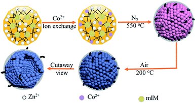
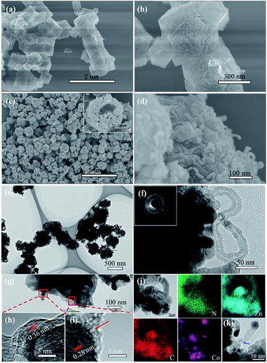
The preparation procedure of the tentacle-like ZnO@NC@CNTs network is illustrated in Fig. 1. The ion-exchange process is carried out between Zn2+ (in ZIF-8) and the added Co2+ to obtain Co-doped ZIF-8, which self-assembles as polyhedra with a coarse surface. During the first-step annealing in nitrogen, organic linkers in the Co-doped ZIF-8 decompose into amorphous N-doped carbon layers, covering the metallic NPs inside and forming a hierarchical yolk–shell morphology. Meanwhile, CNTs are in situ grown with the catalytic effect of Co.27–29 The second-step annealing is carried out in air to obtain fully oxidized ZnO@NC@CNTs. The cutaway view illustrates the yolk–shell structure of the ZnO@NC@CNTs networks.No impurities are found in the full-scale XRD pattern of Co-doped ZIF-8 (compared with pure ZIF-8, Fig. S1a†), indicating good structural preservation of the ZIF-8 phase after the ion exchange. Meanwhile, the partial magnification of the (110) peak is displayed in Fig. S1b† to better present the peak shift. After the Co doping, a slight peak shift is observed, which is more obvious for the (110) peak, suggesting successful replacement of Zn by Co in the resulting sample.30,31 Both Co-doped ZIF-8 and ZIF-8 polyhedra show an average particle size of 400–450 nm (Fig. S2†). However, the surface of Co-doped ZIF-8 becomes quite coarse in comparison with the smooth surface of ZIF-8, implying the success of the ion exchange process on the surface. Thermal stability of the Co-doped ZIF-8 is characterized by TGA (Fig. S3†). Under the protection of N2, weight loss of the Co-doped ZIF-8 occurs between 470 and 650 °C, corresponding to its structural decomposition. Therefore, 550 °C is selected as the first-step annealing temperature, during which organic linkers in the Co-doped ZIF-8 convert into NC, gaseous products, or CNTs. The second-step annealing in air is used to ensure full oxidation of the resulting samples. SEM images of the pure ZIF-8 derived ZnO@NC show the inheritance of the regular polyhedral outlines from the precursor (Fig. 2a and b). The relatively irregular shape of ZnO@NC@CNTs is due to the formation of numerous CNTs on the rough surface (Fig. 2c and d). A closer observation of the ZnO@NC@CNTs (inset in Fig. 2c) reveals a yolk–shell hierarchical structure that is composed of closely connected NPs as subunits. Interestingly, when increasing the Co content in Co-doped ZIF-8, CNTs are not observed in the derivatives (Fig. S4†). Therefore, the Co content is vital for the formation of CNTs. A smaller amount of Co acts as a catalyst to induce the growth of CNTs, while a higher Co content likely contributes to a quick formation of larger Co particles, which show a negligible catalytic effect. Effects of annealing temperature on the structure of ZnO@NC@CNTs were also investigated (Fig. S5†). Although the CNTs were also observed at a higher annealing temperature of 650 °C, most polyhedra collapsed into irregular NPs, which may aggregate during long-term cycling.
TEM images of the ZnO@NC@CNTs further confirm the existence of CNTs with a diameter of about 15 nm (Fig. 2e–g). The contrast between the shell (dark) and the interior yolk (light) is consistent with the SEM observation. The SAED image of the ZnO@NC@CNTs (inset in Fig. 2f) exhibits a ring-like feature, which indicates a well crystallized structure, which is in agreement with the XRD result. The HR-TEM images (Fig. 2h and i) show that the ZnO NPs are covered by amorphous carbon layers (red arrow) and further connected by CNTs. The graphitic interlayer spacing of 0.36 nm (Fig. 2h) corresponds to the (002) plane of the in situ formed CNTs. The Raman spectrum also confirms the existence of CNTs in ZnO@NC@CNTs (Fig. S6†). Generally, the D band (at 1316 cm−1) is associated with sp3-type disordered carbon, and the G band (at 1582 cm−1) derives from sp2-type graphitic carbon.32 The intensity ratio of the D to G band (ID/IG) can be used to determine the graphitization degree of the material. Herein, the ID/IG is calculated to be 0.4, which indicated a higher graphitization degree. The lattice spacing of 0.28 nm (Fig. 2i) is related to the (100) plane of ZnO. The heterogeneous contraction caused the formation of yolk–shell structured ZnO@NC@CNTs.6,33,34 Elemental distribution is examined by TEM-EDS (Fig. 2j). Clearly, C and N co-exist and are uniformly distributed. Co exists predominantly at the edge of polyhedra and the tip of CNTs, confirming its catalytic effect on the growth of CNTs.32 Zn is observed both in the polyhedra and along the CNTs. The blue arrow in Fig. 2k points to ZnO in the CNTs. Wang et al. observed a similar structure and the reason is ascribed to the restructuring of carbon.28
The XRD pattern of the ZnO@NC@CNTs shows main diffractions at 31.82, 34.47, 36.28, 47.57, 56.65, 62.88, 66.46, 68.05, and 69.10 degrees (Fig. 3a), corresponding to the (100), (002), (101), (102), (110), (103), (200), (112), and (201) planes of ZnO (JCPDS: 36-1451), respectively. The absence of Co/CoOx diffractions in the XRD pattern is due to its low content (1.16 wt%, Fig. S7†). The broad peak at 23.9° is the carbon (002) plane. The carbon content in the ZnO@NC@CNTs is determined by TGA (Fig. 3b). In air, weight loss occurred between 400 and 525 °C, corresponding to the decomposition of carbonaceous materials. Based on the TGA result, the amount of carbonaceous materials in ZnO@NC@CNTs is about 21 wt%. Nitrogen isotherms of ZnO@NC@CNTs (Fig. 3c) exhibit typical type IV curves with a H1 hysteresis loop, indicating the mesoporous nature. The narrow and small hysteresis loop in ZnO@NC@CNTs suggests the co-existence of macropores. The pore size distribution curve (Fig. 3d) reveals the existence of mesopores of ∼4.0 nm diameter and abundant macroporous structures, which are likely associated with the presence of CNTs and the voids between the yolk and shell. Notably, the combination of mesopores and macropores can facilitate better penetration of the electrolyte, which is important for enhancing the electrochemical performance. The specific surface area of ZnO@NC@CNTs is 151 m2 g−1, larger than that of ZnO@NC (109 m2 g−1, Fig. S8†).
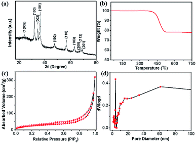 | ||
| Fig. 3 (a) XRD, (b) TGA, (c) N2 isothermals, and (d) the corresponding pore-size distribution curve of the ZnO@NC@CNTs hybrid. | ||
The chemical composition and surface valence of the ZnO@NC@CNTs are investigated by an XPS technique (Fig. 4). The three peaks observed in the high-resolution C 1s spectrum at 284.6, 285.7, and 287.6 eV can be assigned to the sp2 C–C bond, sp3 C–C bond, and C![[double bond, length as m-dash]](https://www.rsc.org/images/entities/char_e001.gif) O/C
O/C![[double bond, length as m-dash]](https://www.rsc.org/images/entities/char_e001.gif) N groups (Fig. 4a), respectively.35 The N 1s spectrum confirms the formation of C–N and C
N groups (Fig. 4a), respectively.35 The N 1s spectrum confirms the formation of C–N and C![[double bond, length as m-dash]](https://www.rsc.org/images/entities/char_e001.gif) N bonds in the ZnO@NC@CNTs (Fig. 4b). Typical peaks are observed at 398.7, 399.8, and 400.7 eV, corresponding to pyridinic N, pyrrolic N, and graphitic N, respectively.35,36 Generally, the N-doped carbon shows enhanced electronic conductivity and wettability compared to the non-doped counterparts.37 The Zn 2p spectrum shows two main peaks at 1045 and 1022 eV (Fig. 4c), which are attributed to Zn 2p1/2 and Zn 2p3/2,38,39 revealing the oxidation state of ZnO. Fitting results of the Co 2p spectrum show two major peaks at 780.3 and 795.5 eV (Fig. 4d). The 15.2 eV energy difference between Co 2p1/2 and Co 2p3/2, together with the presence of the satellite peaks (marked as Sat.), is consistent with the oxidation state in Co3O4.20,40
N bonds in the ZnO@NC@CNTs (Fig. 4b). Typical peaks are observed at 398.7, 399.8, and 400.7 eV, corresponding to pyridinic N, pyrrolic N, and graphitic N, respectively.35,36 Generally, the N-doped carbon shows enhanced electronic conductivity and wettability compared to the non-doped counterparts.37 The Zn 2p spectrum shows two main peaks at 1045 and 1022 eV (Fig. 4c), which are attributed to Zn 2p1/2 and Zn 2p3/2,38,39 revealing the oxidation state of ZnO. Fitting results of the Co 2p spectrum show two major peaks at 780.3 and 795.5 eV (Fig. 4d). The 15.2 eV energy difference between Co 2p1/2 and Co 2p3/2, together with the presence of the satellite peaks (marked as Sat.), is consistent with the oxidation state in Co3O4.20,40
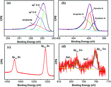 | ||
| Fig. 4 High-resolution XPS spectrum of (a) C 1s, (b) N 1s, (c) Zn 2p, and (d) Co 2p of the ZnO@NC@CNTs hybrid. | ||
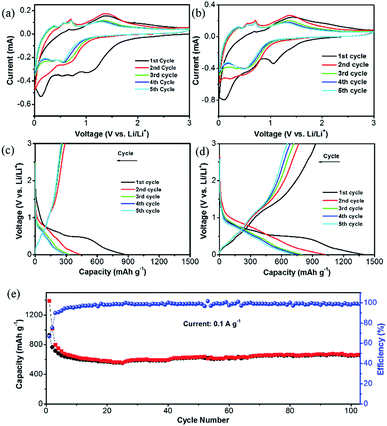
The unique structure of this ZnO@NC@CNTs is expected to benefit the lithiation/delithiation processes. Fig. 5a and b show cyclic voltammetry (CV) curves of the ZnO@NC and ZnO@NC@CNTs electrode for the initial five cycles. For the ZnO@NC@CNTs electrode, three broad peaks were observed at 1.04, 0.57 and 0.15 V in the first cathodic process, which are likely due to the formation of Zn–Li alloys, reduction of ZnO to Zn, and the growth of the solid electrolyte interface (SEI) film (caused by the partial decomposition of the carbonate electrolyte and Li salt), respectively.38,41 In the first anodic process, several successive oxidation peaks were observed (0.3–0.8 V), which could be assigned to the stepwise dealloying process of the Li–Zn alloys (e.g., LiZn, Li2Zn3, and LiZn2).21 The oxidation peak at 1.4 V is related to the decomposition of Li2O by reacting with Zn.42 After the first scan, the major reduction peaks evolved into two peaks at about 0.33 and 0.55 V, which can be assigned to the alloying process of Li–Zn.12,29,30 No significant difference was observed in the subsequent scans, indicating good reversibility of the redox process. Similar phenomena are observed in the ZnO@NC electrode, suggesting that the existence of CNTs did not alter its electrochemical mechanism.
These observations are further supported by the galvanostatic charge/discharge curves, which show a similar tendency (Fig. 5c and d). The high capacity of ZnO@NC@CNTs in the first cycle (1390 mA h g−1) is due to the reduction of ZnO and the formation of the SEI film. Capacity loss is observed in the initial few cycles, which then stabilized after the 3rd cycle (800 mA h g−1 for ZnO@NC@CNTs and 330 mA h g−1 for ZnO@NC). The capacity loss in the initial cycles is mainly caused by an incomplete conversion reaction and irreversible side reactions (e.g. formation of the SEI layer).24 Although the initial coulombic efficiency (ICE) of the ZnO@NC@CNTs electrode (66%) is higher than that of ZnO@NC and some of the electrodes in the literature,42,43 such a value still cannot meet the requirements for practical applications, and further work should be carried out to improve the ICE, such as electrolyte optimization. As shown in Fig. 5e, the ZnO@NC@CNTs electrode exhibited a well-stabilized cycle performance at 0.1 A g−1. After 105 cycles, the ZnO@NC@CNTs can still deliver a high capacity of 672 mA h g−1 with a CE close to 100%.
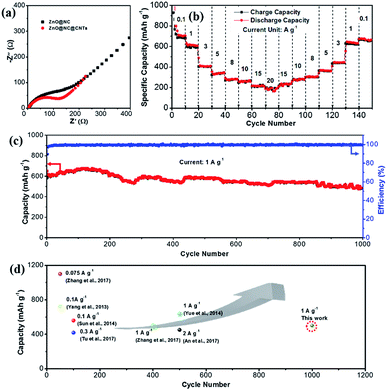
Fig. S9† compares the galvanostatic charge/discharge curves of the ZnO@NC and ZnO@NC@CNTs electrode at various current densities. The ZnO@NC electrode exhibited a low capacity of only 37 mA g−1 when the current increases to 1.0 A g−1. As expected, the rate performance is significantly improved for the ZnO@NC@CNTs sample. High reversible capacities of 800, 617, 409, 356, 294, and 260 mA h g−1 were delivered at 0.1, 1.0, 3.0, 5.0, 8.0, and 10 A g−1, respectively. Even at ultra-high current densities of 15 and 20 A g−1, the ZnO@NC@CNTs electrode still maintains a remarkable capacity of 213 and 180 mA h g−1, respectively. Such an extraordinary rate performance has been rarely reported among ZnO-based electrodes.11,24,28,30,31
To understand the excellent rate performance of ZnO@NC@CNTs, electrochemical impedance spectroscopy (EIS) studies are carried out (Fig. 6a). The semicircle in the Nyquist plots is attributed to the charge transfer resistance (Rct), and the straight line is ascribed to the Warburg impedance (Wo), which is associated with the lithium ion diffusion process. Compared to ZnO@NC, the smaller semicircle of the ZnO@NC@CNTs electrode indicates faster reaction kinetics, which greatly contributes to its superior rate performance. The in situ generated conductive CNTs account for the improved electron transfer efficiency in the ZnO@NC@CNTs composite. The cycling performance of the ZnO@NC@CNTs electrode at different current densities is given in Fig. 6b. After cycling from 0.1 to 20 A g−1 for 80 cycles, a high reversible capacity of 656 mA h g−1 is still retained when the current reverses to 0.1 A g−1 at the 150th cycle, indicating good integrity of the active electrode. XRD and SEM images of the ZnO@NC@CNTs electrode after cycling are determined after fully charging to 3.0 V and then de-assembling in a glovebox. As shown in Fig. S10a,† the typical diffraction peaks of ZnO are recovered after the Li+ insertion/extraction cycles, implying a full recovery of the ZnO phase. Compared with the initial electrode, a broad peak is observed at around 40°, which may be due to the decomposition of the electrolyte. The introduction of carbon black and CMC during the electrode assembling makes it difficult to observe the CNTs in the electrode after cycling (Fig. S10b†). Clearly, ZnO@NC@CNTs polyhedra still well embed in the electrode, and their unique morphology is maintained. All the above results confirm the remarkable durability of the ZnO@NC@CNTs electrode.
The long-term cycling performance of the ZnO@NC@CNTs is examined at 1.0 A g−1 (Fig. 6c). A high reversible capacity of 616 mA h g−1 is obtained at the beginning, which then gradually increases to a maximum value of 684 mA h g−1 at the 150th cycle. This phenomenon is generally observed in the TMO electrodes, which is due to gradual electrolyte wetting effects and/or the electrochemical activation of TMO electrodes.41 After 1000 cycles, the electrode still delivered a high capacity of 501 mA h g−1, corresponding to only 0.019% capacity decay per cycle. Such extraordinary rate and cycling performances of ZnO@NC@CNTs are comparable to or even outperform those of other reported ZnO-based electrodes as displayed in Fig. 6d.44,45 To give a broader overview, electrochemical performance comparison of this novel ZnO@NC@CNTs electrode with that of other types of electrodes is also listed in Table S1,† which further confirms its structural superiority.
The excellent performance of the ZnO@NC@CNTs electrode likely originates from multiple factors. First, the double carbon structure of NC@CNTs covering the ZnO NPs forms a 3D tentacle-like conductive network, which facilitates the local and overall electron transportation and well accommodates the volume change of ZnO during cycling. Second, the combination of mesopores and macropores in the yolk–shell polyhedra can provide better contact between the electrolyte and electrode. Third, the hierarchical nanostructure shortens the diffusion distance for both Li+ ions and electrons. These advantages synergistically result in the improved rate performance and cycle stability of the ZnO@NC@CNTs.
Conclusions
In summary, using Co-doped ZIF-8 as a precursor, a novel structure of NC@CNT double carbon coated tentacle-like ZnO composite has been synthesized. The ZnO@NC@CNTs electrode exhibits excellent Li-storage performance with a high reversible capacity (800 mA h g−1 at 100 mA g−1), an excellent rate capability (capacity of 617, 180 mA h g−1 at 1.0 and 20 A g−1), and good cycling stability (only 0.019% capacity loss per cycle during 1000 cycles at 1 A g−1). The superior electrochemical performance of ZnO@NC@CNTs confirms the structural advantages of this unique structure, which features an outstretched NC@CNT network and a yolk–shell hierarchal structure. This work may provide new insights for the fabrication of high-performance electrodes with integrated conductive carbon materials.Conflicts of interest
There are no conflicts to declare.Acknowledgements
This work was supported by the National Natural Science Foundation of China (21805117, 51602216), Jiangsu Province Science Foundation for Youths (BK20181014), National Natural Science of the Higher Education Institutions of Jiangsu Province (No. 18KJB150015), the Priority Academic Program Development Fund of Jiangsu Higher Education Institutions, and partially funded by the Australian Government through the Australian Research Council's Discovery Projects funding scheme (project DP170101773).Notes and references
- Y. Xu, Q. Li, H. Xue and H. Pang, Coord. Chem. Rev., 2018, 376, 292–318 CrossRef.
- M. Zheng, S. Zhang, S. Chen, Z. Lin, H. Pang and Y. Yu, Nano Res., 2017, 10, 4305–4317 CrossRef.
- T. B. Schon, B. T. McAllister, P. F. Li and D. S. Seferos, Chem. Soc. Rev., 2016, 45, 6345–6404 RSC.
- V. Aravindan, Y. S. Lee and S. Madhavi, Adv. Energy Mater., 2015, 5, 1402225 CrossRef.
- Y. Wang, Z. G. Huang and Y. J. Wang, J. Mater. Chem. A, 2015, 3, 21314–21320 RSC.
- Y. Wang, B. F. Wang, F. Xiao, Z. G. Huang, Y. J. Wang, C. Richardson, Z. X. Chen, L. F. Jiao and H. T. Yuan, J. Power Sources, 2015, 298, 203–208 CrossRef.
- Y. Wang, C. Y. Wang, H. N. Guo, Y. J. Wang and Z. G. Huang, RSC Adv., 2017, 7, 1588–1592 RSC.
- Z. Zheng, Y. Zao, Q. Zhang, Y. Cheng, H. Chen, K. Zhang, M. S. Wang and D. L. Peng, Chem. Eng. J., 2018, 347, 563–573 CrossRef.
- Q. Zhang, H. Chen, L. Luo, B. Zhao, H. Luo, X. Han, J. Wang, C. Wang, Y. Yang, T. Zhu and M. Liu, Energy Environ. Sci., 2018, 11, 669–681 RSC.
- H. Kim, H. Kim, Z. Ding, M. H. Lee, K. Lim, G. Yoon and K. Kang, Adv. Energy Mater., 2016, 6, 1600943 CrossRef.
- Y. Yan, P. Gu, S. Zheng, M. Zheng, H. Pang and H. Xue, J. Mater. Chem. A, 2016, 4, 19078–19085 RSC.
- J. Zhang, P. Gu, J. Xu, H. Xue and H. Pang, Nanoscale, 2016, 8, 18578–18595 RSC.
- K. Q. Zhou, M. L. Kang, X. Q. He, Z. S. Hong, Z. G. Huang and M. D. Wei, J. Mater. Chem. A, 2017, 5, 18138–18147 RSC.
- X. J. Gao, J. W. Wang, D. Zhang, K. Q. Nie, Y. Y. Ma, J. Zhong and X. H. Sun, J. Mater. Chem. A, 2017, 5, 5007–5012 RSC.
- G. L. Xia, L. J. Zhang, F. Fang, D. L. Sun, Z. P. Guo, H. K. Liu and X. B. Yu, Adv. Funct. Mater., 2016, 26, 6188–6196 CrossRef.
- G. Zhang, H. Zhang, X. Zhang, W. Zeng, Q. Su, G. Du and H. Duan, Electrochim. Acta, 2015, 186, 165–173 CrossRef.
- Q. Xie, Y. Ma, X. Wang, D. Zeng, L. Wang, L. Mai and D. L. Peng, ACS Nano, 2016, 10, 1283–1291 CrossRef PubMed.
- L. Wang, G. Zhang, Q. Liu and H. Duan, Mater. Chem. Front., 2018, 2, 1414–1435 RSC.
- X. L. Wang, J. Z. Li, Z. Chen, L. J. Lei, X. P. Liao, X. Huang and B. Shi, J. Mater. Chem. A, 2016, 4, 18783–18791 RSC.
- Y. Wang, C. Y. Wang, Y. J. Wang, H. K. Liu and Z. G. Huang, J. Mater. Chem. A, 2016, 4, 5428–5435 RSC.
- G. H. An, D. Y. Lee and H. J. Ahn, ACS Appl. Mater. Interfaces, 2017, 9, 12478–12485 CrossRef.
- H. Tang, M. Zheng, Q. Hu, Y. Chi, B. Xu, S. Zhang, H. Xue and H. Pang, J. Mater. Chem. A, 2018, 6, 13999–14024 RSC.
- G. Zhang, S. Hou, H. Zhang, W. Zeng, F. Yan, C. C. Li and H. Duan, Adv. Mater., 2015, 27, 2400–2405 CrossRef.
- S. J. Yang, S. Nam, T. Kim, J. H. Im, H. Jung, J. H. Kang, S. Wi, B. Park and C. R. Park, J. Am. Chem. Soc., 2013, 135, 7394–7397 CrossRef.
- T. Jiang, F. Bu, X. Feng, I. Shakir, G. Hao and Y. Xu, ACS Nano, 2017, 11, 5140–5147 CrossRef.
- N. L. Torad, M. Hu, Y. Kamachi, K. Takai, M. Imura, M. Naito and Y. Yamauchi, Chem. Commun., 2013, 49, 2521–2523 RSC.
- N. Sikdar, B. Konkena, J. Masa, W. Schuhmann and T. K. Maji, Chem, 2017, 23, 18049–18056 CrossRef PubMed.
- D. W. Su, M. Cortie and G. X. Wang, Adv. Energy Mater., 2017, 7, 1602014 CrossRef.
- S. N. Zaretskiy, Y. K. Hong, D. H. Ha, J. H. Yoon, J. Cheon and J. Y. Koo, Chem. Phys. Lett., 2003, 372, 300–305 CrossRef.
- W. Zhao, S. Wang, C. Feng, H. Wu, L. Zhang and J. Zhang, ACS Appl. Mater. Interfaces, 2018, 10, 40491–40499 CrossRef.
- K. Zhang, M. Park, L. Zhou, G.-H. Lee, J. Shin, Z. Hu, S.-L. Chou, J. Chen and Y.-M. Kang, Angew. Chem., Int. Ed., 2016, 55, 12822–12826 CrossRef PubMed.
- J. Meng, C. Niu, L. Xu, J. Li, X. Liu, X. Wang, Y. Wu, X. Xu, W. Chen, Q. Li, Z. Zhu, D. Zhao and L. Mai, J. Am. Chem. Soc., 2017, 139, 8212–8221 CrossRef.
- L. Huang, G. H. Waller, Y. Ding, D. C. Chen, D. Ding, P. X. Xi, Z. L. Wang and M. L. Liu, Nano Energy, 2015, 11, 64–70 CrossRef.
- J. Guan, F. Mou, Z. Sun and W. Shi, Chem. Commun., 2010, 46, 6605–6607 RSC.
- L. Zhang, Z. Su, F. Jiang, L. Yang, J. Qian, Y. Zhou, W. Li and M. Hong, Nanoscale, 2014, 6, 6590–6602 RSC.
- F. Zheng, Y. Yang and Q. Chen, Nat. Commun., 2014, 5, 5261 CrossRef CAS.
- Y. Liu, N. Zhang, L. Jiao and J. Chen, Adv. Mater., 2015, 27, 6702–6707 CrossRef CAS.
- H. Zhang, Y. Wang, W. Zhao, M. Zou, Y. Chen, L. Yang, L. Xu, H. Wu and A. Cao, ACS Appl. Mater. Interfaces, 2017, 9, 37813–37822 CrossRef CAS.
- Y. Q. Zhang, Y. B. Lu, S. Feng, D. D. Liu, Z. L. Ma and S. Y. Wang, J. Mater. Chem. A, 2017, 5, 22512–22518 RSC.
- Y. Q. Fan, N. Zhang, L. Y. Zhang, H. B. Shao, J. M. Wang, J. Q. Zhang and C. N. Cao, J. Electrochem. Soc., 2013, 160, F218–F223 CrossRef CAS.
- Z. H. Li, X. Yu, Y. Liu, W. X. Zhao, H. Zhang, R. M. Xu, D. H. Wang and H. Shen, J. Mater. Chem. A, 2016, 4, 19123–19131 RSC.
- X. Sun, C. G. Zhou, M. Xie, H. T. Sun, T. Hu, F. Y. Lu, S. M. Scott, S. M. George and J. Lian, J. Mater. Chem. A, 2014, 2, 7319–7326 RSC.
- Y. L. Zou, Z. G. Qi, Z. S. Ma, W. J. Jiang, R. W. Hu and J. L. Duan, J. Electroanal. Chem., 2017, 788, 184–191 CrossRef CAS.
- Y. Zhang, Y. Lu, S. Feng, D. Liu, Z. Ma and S. Wang, J. Mater. Chem. A, 2017, 5, 22512–22518 RSC.
- H. Yue, Z. Shi, Q. Wang, Z. Cao, H. Dong, Y. Qiao, Y. Yin and S. Yang, ACS Appl. Mater. Interfaces, 2014, 6, 17067–17074 CrossRef CAS.
Footnote |
| † Electronic supplementary information (ESI) available. See DOI: 10.1039/c8na00228b |
| This journal is © The Royal Society of Chemistry 2019 |

