 Open Access Article
Creative Commons Attribution 3.0 Unported Licence
Resistant energy analysis of self-pulling process during dropwise condensation on superhydrophobic surfaces†
Aref
Vandadi‡
a,
Lei
Zhao‡
b and
Jiangtao
Cheng
 *ab
*ab
aDepartment of Mechanical and Energy Engineering, University of North Texas, Denton, TX 76207, USA.
bDepartment of Mechanical Engineering, Virginia Polytechnic Institute and State University, Blacksburg, VA 24061, USA. E-mail: chengjt@vt.edu
First published on 20th December 2018
Abstract
Recently the development of superhydrophobic surfaces with one-tier or hierarchical textures has drawn increasing attention because enhanced condensation heat transfer has been observed on such biomimetic surfaces in well-tailored supersaturation or subcooling conditions. However, the physical mechanisms underlying condensation enhancement are still less understood. Here we report an energy-based analysis on the formation and growth of condensate droplets on two-tier superhydrophobic surfaces, which are fabricated by decorating carbon nanotubes (CNTs) onto microscale fluorinated pillars. Thus-formed hierarchical surfaces with two tier micro/nanoscale roughness are proved to be superior to smooth surfaces in the spatial control of condensate droplets. In particular, we focus on the self-pulling process of condensates in the partially wetting morphology (PW) from surface cavities due to intrinsic Laplace pressure gradient. In this analysis, the self-pulling process of condensate tails is resisted by adhesion energy, viscous dissipation, contact line dissipation and line tension in a combined manner. This process can be facilitated by adjusting the configuration and length scale of the first-tier texture. The optimum design can not only lower the total resistant energy but also favor the out-of-plane motion of condensate droplets anchored in the first-tier cavity. It is also shown that engineered surface with hierarchical roughness is beneficial to remarkably mitigating contact line dissipation from the perspective of molecular kinetic theory (MKT). Our study suggests that scaling down surface roughness to submicron scale can facilitate the self-propelled removal of condensate droplets.
1. Introduction
During dropwise condensation on a superhydrophobic surface with micro/nano-structures, condensate droplets can form and grow in three types of morphology, i.e., the Cassie state,1 the Wenzel state,2 and the partially wetting morphology (PW).3 A Cassie-state droplet stands on top of surface roughness and is characterized by a large contact angle, small contact angle hysteresis (<5°) and exceptional mobility. These features could lead to self-propelled removal of condensate droplets and consequently facilitate rapid purging of the condenser surface. Nonetheless, the air cushion underneath a Cassie droplet impedes efficient heat transfer. By contrast, a droplet in the Wenzel state4,5 impenetrates surface cavities to facilitate heat transfer between the condensates and the condenser surface, but exhibits strong adhesion to the structured surface. Different from the Cassie state and the Wenzel state, droplets in the PW morphology only partially fill the cavities underneath3 or just the first-tier cavities in hierarchical roughness, i.e., micro-Wenzel nano-Cassie state. In this case, the PW condensates can form a relatively efficient thermal conduction path via bridging the main gap between the condensates and condenser surface, and in the meanwhile remain comparatively mobile to avoid condensate flooding on the condenser surface. Zhang et al. studied dropwise condensation on nanostructured microporous surfaces in environmental scanning electron microscope (ESEM) and observed the self-pulling of a single PW droplet without coalescence and coalescence-induced PW to Cassie state transition, i.e., PW-Cassie transition.6 Therefore, the PW morphology for condensate droplets is desired for continuous dropwise condensation (CDC) with enhanced heat transfer.7,8Achieving sustained dropwise condensation on micro/nano-engineered surfaces places stringent requirements on the proper design of the configuration and length scale of surface structures and necessitates meticulous control of nucleation density and droplet morphology, which entail deep understanding of the underlying mechanisms governing condensate growth dynamics. Recently droplet jumping condensation on a nanostructured superhydrophobic CuO surface was demonstrated to enhance heat transfer efficiency by 30%.8 However, these condensation experiments were conducted in carefully-tailored and mild thermal conditions with a low supersaturation (<1.12) and a relatively low critical heat flux (<8 W cm−2). Otherwise, condensate flooding on the condenser surface would occur and give rise to the unacceptable rise of thermal resistance thereon. Based on interfacial energy analysis, Rykaczewski et al. reported that the growth mechanism of individual condensate microdroplets on nanotextured surfaces is universal and independent of the surface architecture.9 The key role of the nanoscale topography is to confine the base area (i.e., wet spot) of forming embryos, which allows droplets to grow only through contact angle increase. Through observing condensation on one tier of nanowires in ESEM, they claimed that the formation of condensate nuclei could be controlled close to the top of the nanostructures.9 But how to form discrete condensate distribution on the surface of nanowires postponing flooding as well as validation of condensation heat transfer enhancement were not systematically studied in this work. Up to date, the rationale for designing biomimetic surfaces with optimum configuration of surface roughness in real thermal conditions are still lacking. Most of such reported condenser surfaces3–11 are characterized by fortuitous design and configuration, rather than driven by the fundamental principles of thermal and physical processes. In order to achieve sustained dropwise condensation on an engineered surface, it is imperative to understand the formation of condensate embryos, nucleation site and condensate density distribution, the dynamic growth of condensate droplets and evolution of droplet morphology.3
In this paper, we report our energy-based analysis of growth dynamics of dropwise condensates on biomimetic surfaces with two-tier hierarchical textures and their structural optimization. In particular, we focus on the intrinsic energetics associated with the transition of a condensate tail, which is entrapped in the first tier cavity but exhibits Cassie state relative to the second-tier nanoscale roughness (exclusively referred to as the PW condensates in this work), to the Cassie state through the self-pulling mode without coalescence with neighbouring droplets. In this analysis, the resistant energy associated with the expulsion of a condensate tail in the PW morphology is divided into three main parts. The first part is the adhesion energy due to the adhesion of the tail to the nanotextures in the first tier cavity. The second part is the viscous dissipation during the upflow of the condensate tail from the first tier cavity to the bulky portion of the PW droplet. The third part is related to contact line dissipation that occurs within three phase (liquid/vapor/solid) contact zone of the condensate tail. Besides, the effect of line tension on condensate state transition is also discussed. By minimizing the energetic resistance, the first tier roughness is optimized to favour the PW-Cassie transition of a condensate tail in the cavity. This work can advance our understanding on the growth dynamics of PW condensate droplets and aid the design of micro/nano-engineered lotus-leaf-like condenser surfaces promoting continuous dropwise condensation.
2. Experimental methods
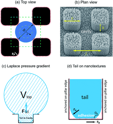
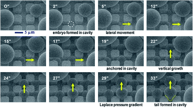
In our dropwise condensation studies we fabricated biomimetic lotus-leaf-like surfaces with two-tier hierarchical structures as shown in Fig. 1(a) and (b).12 Regularly-positioned silicon micropillars12–16 were adopted as the first-tier texture, i.e., the primary roughness, and carbon nanotubes (CNTs) were decorated on the micropillars as the second-tier texture, i.e., the secondary roughness. The width, height and center-to-center pitch (period) of the first tier pillars are denoted by b, h and l, respectively, while rp stands for the corner radius of the first tier pillars. In this work, the first tier has a solid fraction of ff = b2/l2 ≈ 0.32 and the second tier nanostructures has a solid fraction of fn ≈ 0.25, so the solid fraction of the two-tier textures is f = fffn = 0.08, which is much smaller than 1.11,12 As-formed micro/nanostructured surface was conformally coated by a thin layer of fluoropolymer (FluoroPel™ PFC1601V, Cytonix or Teflon®) to strengthen its hydrophobicity to superhydrophobicity. This type of engineered surfaces with regular geometries provides an ideal platform to study the dynamics of droplet growth and expulsion of the tail of a PW condensate droplet in a unit cell, i.e., the cavity volume surrounded by four micropillars as shown in Fig. 1(b), as well as the spatial distribution of condensate droplets.Our study of surface roughness optimization starts with the two-tier hierarchical structures as introduced above. Fig. 2 shows a close inspection of condensation process in ESEM. The formation of nucleation embryos in nanostructure cavities and in the first tier pillar cavities is ubiquitous since the critical nucleation radius of water is around tens of nm. The free energy barrier to condensate formation in the roughness cavity, i.e., the change in the free energy associated with embryo formation, could be calculated as:17,18
 | (1) |
Furthermore, we compared condensation process of water vapor on the two-tier superhydrophobic surface in ESEM12 with that on a smooth hydrophobic surface, which was formed by spin-coating a thin layer of fluoropolymer (FluoroPel™ PFC1601V, Cytonix or Teflon®) on a silicon wafer. The average sizes of condensate droplets during condensation on the two surfaces were calculated and plotted in Fig. 3(a). On the smooth surface, condensate droplets continuously coalesced with neighbouring condensates forming larger droplets, but the majority of the condensates still remained on the surface (see ESI†). Consequently, the average droplet diameter continuously grew as shown in Fig. 3(a). On the contrary, the average drop diameter on the two-tier surface started growing at the early stage of condensation but reached a saturated value of ∼15 μm during the subsequent stage. This could be explained by the self-cleaning ability of the two-tier superhydrophobic surfaces, which removes the condensate droplets by coalescence-induced jumping.12 The surface coverages of condensates on both the smooth and two-tier surfaces are plotted versus time in Fig. 3(b). Initially surface coverages on both surfaces increased along with condensation and got flattened out respectively following the early stage. For smooth hydrophobic surface the surface coverage levelled out at 0.58 while the superhydrophobic surface coverage got stabilized at around 0.28, which is almost half of the smooth surface coverage. Maintaining a higher percentage of unwetted bare surface could lead to less thermal resistance towards condensation, which can potentially enhance the rate of condensation and subsequently increase heat transfer on the two-tier structured surface.
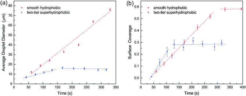 | ||
| Fig. 3 (a) Average droplet diameter and (b) surface coverage in the condensation process on smooth and two-tier surfaces. | ||
3. Results
3.1 Theoretical models
Regarding a forming PW condensate, its tail is entrapped in the cavity of primary roughness but could be expelled either by self-pulling6 because of morphing-induced Laplace pressure gradient (intrinsic mechanism), or jump off via coalescence with neighbouring droplets (extrinsic mechanism). Nevertheless, immobile coalescence13 has been observed in the event that the released surface energy in coalescence is smaller compared to adhesion work, viscous dissipation consumption and contact line dissipation/pinning.19 For the purpose of structural optimization of surface roughness, we are not concerned with interactions (e.g., coalescence) between condensate droplets already sitting on top of surface roughness. Alternatively, we focus on the resistant energy preventing a single condensate tail from transitioning to the Cassie state, which would be the favourable state for agile condensate removal. In our analysis, we divide the total resistance energy into three major parts, i.e., adhesion energy, viscous dissipation and contact line dissipation.Adhesion energy is one of the main barriers impeding the PW-Cassie transition as discussed in previous studies.20 The crucial step to form a mobile Cassie droplet is to first detach the condensate tail from the cavity and subsequently to expel the tail to the top of the pillars (PW-Cassie transition). The surface free energy change during the detachment of the tail per unit surface area would be Wadh = σ(1 + cos![[thin space (1/6-em)]](https://www.rsc.org/images/entities/char_2009.gif) θ),21 where θ ≈ 115° is the Young's contact angle on the fluoropolymer-coated (FluoroPel™ PFC1601V, Cytonix or Teflon®)12 smooth surface. The contact area of the tail with the nanostructures on the cavity base is fnπrb2, where
θ),21 where θ ≈ 115° is the Young's contact angle on the fluoropolymer-coated (FluoroPel™ PFC1601V, Cytonix or Teflon®)12 smooth surface. The contact area of the tail with the nanostructures on the cavity base is fnπrb2, where  is the radius of the tail base, W = 2(l − b), and θn ≈ 150° is the contact angle on the second tier nanostructures (Fig. 1(d)). The contact area of the tail along the pillar sidewalls is ∼Lclh, where Lcl is the length of the three-phase contact line as illustrated by the pink segments in Fig. 1(a) and the derivation of Lcl can be found in the ESI.† Then the work required to detach the condensate tail from the cavity is
Eadh = Wadh × Aadh = σ(1 + cos![[thin space (1/6-em)]](https://www.rsc.org/images/entities/char_2009.gif) θ)fn(πrb2 + Lclh) θ)fn(πrb2 + Lclh) | (2) |
Consequently, actual contact area Aadh is scaled down by a factor of fn due to the secondary nano-roughness.
The viscous dissipation incurred by the internal convection of a PW droplet makes another part of the resistant energy. As evidenced by the nonuniform heat transfer on the base of a condensate droplet, condensate droplets are usually not in a thermodynamically equilibrium state.22 The gradually expanding upper portion of a PW condensate leads to a decreasing capillary pressure therein whereas its tail portion remains under high capillary pressure. Thus-generated internal pressure gradient23,24 would pull the condensate tail upward, and at a specific size the droplet base would detach from the first tier valley, leading to self-pulling (or self-jumping) of the stretched PW droplet without coalescence. The self-pulling mode has been recently reported by Aili et al.6 in their study of condensation on nanostructured microporous surfaces. To analyze self-pulling of a condensate tail in a first tier cavity, we assumed Laplace pressure force F as the intrinsic mechanism in this study and the magnitude of viscous dissipation during the tail elevation is estimated as25
 | (3) |
 | (4) |
Regarding the dynamic growing process of a droplet on the pillar-arrayed surface, the surface tension σ, the viscosity μ and the inertia govern the liquid motions. For liquid, the ratio of viscous dissipation to surface tension and inertia is characterized by the Ohnesorge number Oh = μ/ρσL, where ρ and L are the fluid density and the characteristic length scale (L = pillar height h in this work, i.e., the height of the condensate tail in the cavity), respectively. In typical vapor condensation experiments, Oh ∼0.1 (ρ = 998 kg m−3, μ = 0.001 Pa s, σ ≈ 0.075 N m−1 for water at 5 °C and 1 bar, and L is on the order of μm) indicating viscous dissipation starts to dominate the surface energy effect19 and the self-pulling elevation of the tail is a capillary-inertial process (Oh < 1) in the cavity. Thus the average velocity could be assumed to be U/2 and the upward displacement of the mass center of the tail is h/2, then the time scale for the PW-Cassie transition can be estimated as  , which is actually scaled as the capillary time (see ESI† for detailed derivation). By the momentum law the velocity of the droplet tail could be scaled as
  .
.
Since the size of the entrapped tail is much smaller than the capillary length of 2.7 mm of water, the bottom portion of the tail is assumed to be a spherical cap as shown in Fig. 1(d). So the curvature of the bottom tail can be estimated as rs = W/2![[thin space (1/6-em)]](https://www.rsc.org/images/entities/char_2009.gif) cos(π − θn).21 Given the larger radius of the condensate droplet on top (Fig. 1(c)), the pressure in the top portion of the tail should be much smaller than the bottom pressure. Consequently the pressure difference in the tail can be estimated as
cos(π − θn).21 Given the larger radius of the condensate droplet on top (Fig. 1(c)), the pressure in the top portion of the tail should be much smaller than the bottom pressure. Consequently the pressure difference in the tail can be estimated as  and the vertical driving force F is scaled as
 | (5) |
As such, depinning of the solid–liquid–vapor contact line in the cavity occurs when a certain value of critical pressure inside a droplet is surmounted.26 With the tail mass m ≈ ρπW2h/4, we have  and the energy loss due to viscous dissipation in the self-pulling process could be estimated as
 | (6) |
Our vapor condensation study in ESEM12 and other moisture condensation studies11 have observed extensive immobile coalescence on superhydrophobic surfaces, which can be partially ascribed to contact line pinning and hence contact line dissipation.27,28 Therefore, contact line dissipation should be given a careful evaluation in the energy analysis. From the point of view of molecular kinetic theory (MKT),29–33 the displacement of the three-phase contact line is determined by the forward and backward jumping frequencies, K+ and K−, of liquid molecules in the contact zone. At equilibrium, K+ = K− = K0, where  is the equilibrium displacement frequency, kB is the Boltzmann constant, T is the absolute temperature, and vL is the unit volume of flow of the liquid at the contact line. The activation free energy ΔG arises from the solid–liquid interaction, which can be taken as the work of adhesion, and the liquid–liquid viscous effect.33 Disturbed by an external driving work (shear stress, capillary force, hydration force, van der Waals interactions, etc.), K+ and K− become unbalanced and the contact line will start moving. For the condensate tail in the cavity, the out-of-balance surface tension force is given by σsv − σsl − σ
![[thin space (1/6-em)]](https://www.rsc.org/images/entities/char_2009.gif) cos
cos![[thin space (1/6-em)]](https://www.rsc.org/images/entities/char_2009.gif) θd, where σsv is the solid-vapor interfacial tension, σsl is the solid–liquid interfacial tension, θd is the dynamic contact angle (i.e., contact angle associated with the moving contact line) of condensate on the nanostructures inside the cavity. When the difference between the static contact angle θ0 and the dynamic contact angle θd is not significant, the contact line velocity uc can be linearized as (see ESI† for detailed derivation)
θd, where σsv is the solid-vapor interfacial tension, σsl is the solid–liquid interfacial tension, θd is the dynamic contact angle (i.e., contact angle associated with the moving contact line) of condensate on the nanostructures inside the cavity. When the difference between the static contact angle θ0 and the dynamic contact angle θd is not significant, the contact line velocity uc can be linearized as (see ESI† for detailed derivation)
 | (7) |
 is the contact line friction coefficient (CLFC) that determines the dissipation rate ξuc2 within the three-phase contact zone,34 λ is the jumping step length of liquid molecules and n is the number density of the adsorption sites on the surface.
Instead of polyethylene terephthalate,30 fluoropolymer-based polytetrafluoroethylene (PTFE) was used as the water repellent coating material on the engineered structures in this work. Little work has been done on contact line friction of water on smooth or rough surfaces coated by fluoropolymer. Therefore we used molecular dynamics (MD) simulation to study the wetting behaviour of water on a PTFE surface in the framework of MKT.35–38 For water droplets of tens of nanometers in diameter on a smooth PTFE surface, our MD simulation shows CLFC on the smooth PTFE surface  ∼ 1.2 × 10⁻³ Pa s at 5 °C, which is on the same order of magnitude as the dynamic viscosity of water. For condensate tails entrapped in the first tier cavities, the body of each condensate tail is actually in direct contact with the secondary CNT structures, which is conformally coated by PTFE. Since the condensate tail stays at the Cassie-state with regard to the second-tier nanoroughness, the contact line dissipation is scaled down by a factor of fn. From Rayleigh dissipation function, the total energy loss due to contact line dissipation in the first tier cavity can be evaluated as:
 | (8) |
Combining eqn (2), (6) and (8) yields the self-pulling energy barrier of the PW-Cassie transition including adhesion energy Eadh, viscous dissipation Evis and contact line dissipation Ecl in a first tier cavity:
 | (9) |
Using pillar height h as the characteristic dimension, the nondimensionalized form of eqn (9) becomes:
 | (10) |
The dimensionless variables are represented with an asterisk, e.g.,  . It is noteworthy that the Ohnesorge number Oh is defined as Oh = μ/ρσh in this analysis. This energy barrier must be overcome by a condensate tail in order to accomplish the PW-Cassie transition via self-pulling mode.
3.2 Optimization of surface roughness by resistant energy analysis
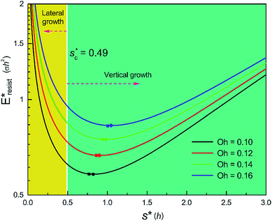
We conducted parametric studies to characterize the influence of the first tier pillar geometry on the energy barriers. Fig. 4 shows the variation of resistant energy versus nondimensional cavity width s* (i.e., s* = s/h and s = l − b) with the solid fraction f = 0.08. It can be seen that for each Oh number there does exist an optimum
  (and hence optimum pillar width
  ) leading to the minimum resistance.
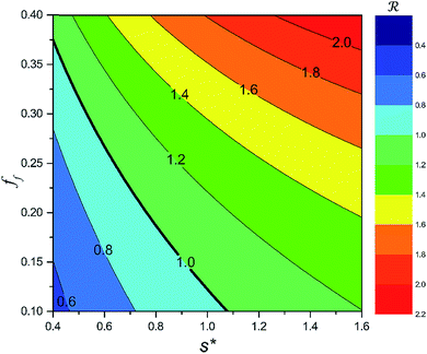
On the other hand, an ideally-structured condenser surface should be able to promote out-of-plane (vertical) growth of condensate droplets rather than in-plane (lateral) spreading.10 We compared surface energy change ΔEvertical due to an infinitesimal vertical growth dz with surface energy change ΔElateral induced by an infinitesimal lateral growth dr. The energy ratio  as a function of cavity width s* and first tier solid fraction ff is plotted in Fig. 5 (see ESI† for detailed derivation). For
 ![[scr R, script letter R]](https://www.rsc.org/images/entities/char_e531.gif) < 1, the first tier pillars are able to block the lateral wetting of condensates towards the neighbouring cavities, indicative of a thermodynamically favorable configuration of surface structures. The critical cavity width
< 1, the first tier pillars are able to block the lateral wetting of condensates towards the neighbouring cavities, indicative of a thermodynamically favorable configuration of surface structures. The critical cavity width  with
with ![[scr R, script letter R]](https://www.rsc.org/images/entities/char_e531.gif) = 1 and the optimum cavity width
= 1 and the optimum cavity width  with minimum resistant energy are shown in Fig. 4 for various Oh (i.e., pillar height h) values. It can be seen that for each cavity width larger than the critical width
  there does exist an optimum cavity size
  , which not only minimizes resistant energy but also favors vertical growth of condensates. Importantly, by minimizing the resistant energy, the condensate tails formed in the cavities are more apt to the PW-Cassie transition via self-pulling mode. It needs to be mentioned that pillar height h cannot be arbitrarily short in engineered surface design not only for maintaining proper surface roughness but also for preventing potential sagging of condensate droplets in to the structure cavities even after the PW-Cassie transition.39
From Fig. 4, it is clear that for each Oh (hence the height h of the pillars) there exists an optimum cavity width  leading to the lowest resistant energy in a unit cell. Actually, the value of optimum
  is constrained by the vertical growth preference factor
 ![[scr R, script letter R]](https://www.rsc.org/images/entities/char_e531.gif) and sagging phenomenon40 of condensate droplets respectively. The critical cavity width
and sagging phenomenon40 of condensate droplets respectively. The critical cavity width  , which is set by
 ![[scr R, script letter R]](https://www.rsc.org/images/entities/char_e531.gif) = 1, defines the lower bound for
= 1, defines the lower bound for  . The upper bound for
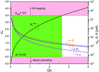
  can be determined by preventing the occurrence of complete sagging, i.e., Cassie to Wenzel transition, of the condensate droplet after the PW-Cassie transition. The critical pillar height hsag for the occurrence of complete or full sagging of a droplet sitting on top of pillars is (see ESI†)
 | (11) |
 preventing complete sagging occurrence becomes
 | (12) |
Assuming θa ≅ θn ≅ 150° on the CNTs with fn = 0.25, the upper limit of cavity width bounded by sagging occurrence on the textured surface is  .
.
Fig. 6 shows the effects of Oh on the nondimensional optimum cavity width  , dimensional optimum cavity width sm, the pillar height h and pillar width b of the primary roughness. As Oh approaches to 0.035, indicative of a pillar height of ∼15 μm, the optimum
  reaches the critical lower bound
  , beyond which the surface structures cannot effectively prevent the undesired lateral spreading. As Oh increases, the nondimensional optimum
  increases whereas the optimum cavity width sm, pillar height h and pillar width b eventually decrease to the submicron levels, respectively. When Oh approaches to 2.7, indicative of the pillar height as low as tens of nanometers, the optimum
  gets close to the upper bound
  . But between the lower and the upper limits for
  , the shorter the height of the pillar (and hence the narrower the width of the cavity), the sooner the cavity is filled up with condensate and the sooner the self-pulling stage can be achieved. Fig. 7 shows a portion of the Fig. 6 for Oh in the range of 0.1–0.3. The 1 μm line for sm, b and h is displayed to demarcate the micron and submicron regimes. As Oh increases, the values of sm, b and h decrease as shown in Fig. 6 as well. For Oh > 0.2, the values of sm, b and h enter the submicron regime. Therefore, having both tiers of roughness in the submicron scale and also designing the first tier structure to match the optimum value shown in Fig. 4 (there exists an optimum value for each Oh, and hence for each pillar height h) can facilitate the PW condensate removal as a result of the remarkably alleviated resistant energy. On the other hand, the design of such structured surfaces with both the two tier roughnesses in submicron scale also imposes a limitation on how small the first tier can be, which is beyond the scope of this work.
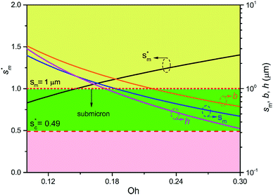 | ||
Fig. 7 The nondimensional optimum cavity width  , pillar height h, pillar width b and optimum cavity width sm with respect to the Oh number in the range of 0.1–0.3. , pillar height h, pillar width b and optimum cavity width sm with respect to the Oh number in the range of 0.1–0.3. | ||
We further compared in Fig. 8 the evolution of viscous dissipation  , adhesion work
  , contact line dissipation
  and resistant energy
  with pillar gap s* while f = 0.08 and Oh = 0.1. Same as resistant energy
  , the above energy factors are nondimensionalized by σh2. Increasing pillar gap s* has a prominent mitigating effect on viscous dissipation and contact line dissipation as opposed to an intensified effect on adhesion. As discussed above, there exists an optimum cavity size
  giving rise to the minimum resistant energy
  . It is noteworthy that for
  the work of adhesion, viscous dissipation and contact line dissipation are all prominent, but for
  the resistance is dominated by viscous dissipation and contact line dissipation.
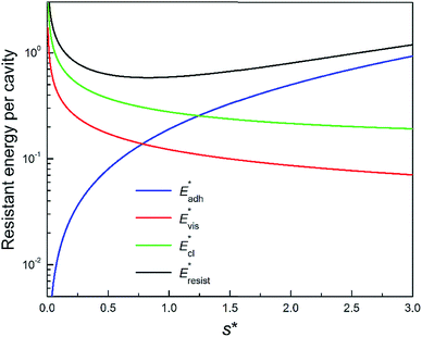 | ||
Fig. 8 Variation of the nondimensionalized viscous dissipation  , adhesion work , adhesion work  , contact line dissipation , contact line dissipation  and resistant energy and resistant energy  in a cavity with roughness spacing s* (f = 0.08 and Oh = 0.10). in a cavity with roughness spacing s* (f = 0.08 and Oh = 0.10). | ||
3.3 Condensate spatial density influence on resistant energy
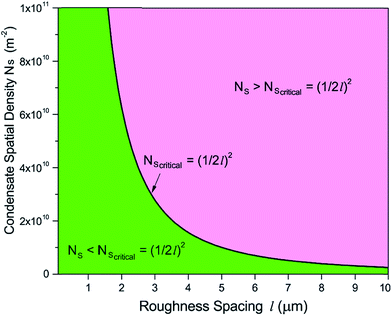
The topography of a condenser surface has significant influence on nucleation site density as nucleation sites generally increase with the decrease of the characteristic size of surface roughness. Nevertheless, the importance of controlling nucleation density in pursuit of CDC could be evidently illustrated by selecting different hypothetical condensate spatial densities, indicative of the influence of surface structure density on resistant energy. In this analysis, condensate site on a two tier rough surface refers to a first tier cavity with a forming PW condensate entrapped therein after the initial nourishing process of a nucleate embryo.Discrete dropwise condensates should be methodically maintained while the uncontrolled lateral spreading should be avoided or at least delayed during condensate growth in surface cavities, otherwise dropwise condensation may not continue and the surface would eventually get flooded. To satisfy this criterion the spacing between the condensate sites L should be at least 2 times the roughness period or spacing l, i.e.,  .41 The spacing between condensate sites could be given by
  , where Ns denotes the density of condensate droplets. Then the above site criterion can be rewritten as
 | (13) |
Fig. 9 shows the critical values of condensate sites versus roughness spacing l (eqn (13)). The region beneath the critical curve (green area) represents the condensate site densities satisfying dropwise condensation criterion mentioned above. For Ns values above the critical curve (red area) multiple condensates may form around a unit cavity. As these condensates grow, they would merge with those in neighbouring cavities leading to film condensation and may eventually flood the surface. Regarding one of our two-tier superhydrophobic surfaces with l0 = 9 μm, the benchmark site criterion is  . In a general case with varying roughness spacing l, the critical condensate site density Ns,critical can be related to Ns0 as
 | (14) |
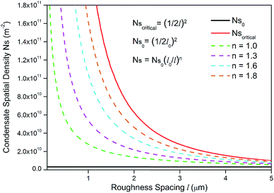
To guarantee Ns falls beneath the critical curve in Fig. 9, the following criterion regarding the power n of  must be met
 | (15) |
As shown in Fig. 10, the power n of  was chosen to be 1, 1.3, 1.6, and 1.8 respectively to make Ns remain below the critical curve, i.e., in the CDC region. These condensate site density curves are hypothetically chosen in order to provide an insight into the effect of condensate site density on the overall resistant energy of surfaces of different roughness characteristics.
It can be seen in Fig. 11 that for different condensate site densities the overall resistant energy of the surface displays various behaviours as the primary cavity size s decreases. When the condensate site density is maintained at a moderate level (n = 1 or 1.3), the resistant energy of the surface is approximately in proportion to s. In contrast, as the condensate site density rises to even higher levels (n = 1.6 or 1.8), the overall resistant energy of the surface could increase especially for smaller roughness sizes, despite the resistant energy of a unit cell is decreasing (also see ESI†). In other words, the significant increase in the number of condensate sites leads to more condensate tails formed in the cavities of first-tier structures. Therefore, the overall resistant energy rises as a result of the increase of condensate sites. From the experimental point of view, to maintain condensate sites within a proper range (n < 1.6), superbiphilic surfaces formed by lithographically patterning superhydrophilic islands on superhydrophobic surfaces42 or chemical micropatterns43 can be employed for spatial control of at least microscale droplets during condensation, which is a new research theme in dropwise condensation on engineered surfaces.
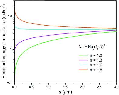 | ||
| Fig. 11 Resistant energy per unit area versus primary cavity size s for different hypothetical condensate site densities. | ||
4. Discussion
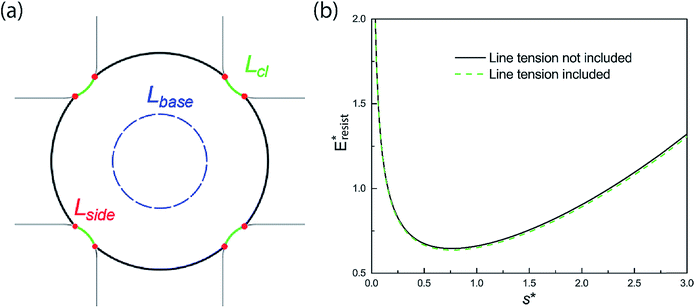
Even though it has been a challenge to realize sustained CDC on engineered surfaces in real applications, there have recently been reported experimental works demonstrating jumping-droplet-enhanced condensation on nanostructured surfaces in carefully-designed vapor chambers.8,24,44–46 Instead of using conventional wicks, Boreyko and Chen developed a novel vapor chamber with jumping-drop liquid return,44 in which superhydrophobic condenser is composed of 150–300 nm clusters of 50–100 nm silver nanoparticles on copper, and the overall lumped heat transfer coefficient has reached as high as 55 kW m−2 K−1. Both tiers of silver nanoparticles structures on the condenser are in nanoscale, which is in excellent agreement with our analysis of structural optimization. Two other recent works, which used superhydrophobic Si nanowires45 and hydrophobic Cu nanowires46 respectively on their condensers, have confirmed enhanced condensation heat transfer due to droplet jumping behaviour. It is noteworthy that these nominal single layer nanostructures actually consist of bundles of nanowires with microscale gaps, indicative of essentially two-tier hierarchical structures. Even though our resistant energy analysis starts with two-tier structures, it can be easily extended to surfaces with nominal one-tier nanotextures,8 which may be essentially composed of dual-scale roughness as more obvious in the clustered ribbed-nanoneedle structures.24 Due to the irregular and nonuniform geometries of surface roughness present in these works, we could only conduct a rough comparison of these experimental studies with our theoretical analysis. Based on the major features or characteristic lengths extracted from the surface structures of the abovementioned works, the structural comparison in the form of scattered points is shown in Fig. S8.† It can be seen that most of these surface configurations satisfy the continuous dropwise condensation criteria, which is illustrated by the central green region, proposed by us. In the condensation experiment by Yang et al.,46 the nanofibers are ∼20–30 μm tall with a high aspect ratio so that condensate droplets may be initially formed in the Cassie state instead of in the partial wetting (PW) morphology, which is not in accord with the situation of the PW-Cassie transition as discussed in our analysis.On the other hand, when the surface roughness approaches nanoscale, the intrinsic line tension effect47 may play a certain role in the PW-Cassie transition. For a PW droplet anchored in the surface cavities, the line tension occurs at the three-phase contact line and its distribution is illustrated in Fig. 12(a). The resistant energy Elt caused by line tension can be calculated by:
| Elt = σκ(Lcl + Lbase + Lside) ≈ σκ(Lcl + 2πrb + 8 h) | (16) |
σκ = (σsv − σsl − σ![[thin space (1/6-em)]](https://www.rsc.org/images/entities/char_2009.gif) cos cos![[thin space (1/6-em)]](https://www.rsc.org/images/entities/char_2009.gif) θ0)κ θ0)κ | (17) |
We also studied the relative strength eE of line tension in the resistant energy associated with the PW-Cassie transition, which is defined as
 | (18) |
And the values of eE for different Ohnesorge numbers are shown in Table 1.
| Oh | 0.10 | 0.12 | 0.14 | 0.16 |
|---|---|---|---|---|
| e E | 1.16% | 1.36% | 1.53% | 1.68% |
Therefore, according to our analysis, line tension is not a dominant factor in resisting PW-Cassie transition at least in nanoscale roughness.
5. Conclusions
Continuous and sustained dropwise condensation on engineered surfaces places stringent requirements on careful design of surface structure length scale and geometry, as well as meticulous control of condensate morphology and spatial distribution.49–51 We carried out optimization of two-tier structured surfaces by minimizing the resistant energy that impedes the PW-Cassie transition. Our analysis of condensate growth in a first tier cavity shows that there does exist an optimum first tier geometry that can tremendously mitigate the resistant energy while allowing condensates to preferentially grow in the out-of-plane direction. We further showed that reducing surface roughness to submicron scale could be promising in achieving sustainable dropwise condensation due to the even lower resistance to the PW-Cassie transition. In addition to playing an important role in confining and controlling embryo formation, the second-tier nanotextures can effectively mitigate contact line dissipation and contact line pinning of the condensates. On the overall condenser surface, discrete condensate distribution is desired for delaying condensate flooding. Due to the relatively smaller energy barrier (Gibbs free energy) in the cavities of first tier structures, most of the condensate droplets in the PW state can be discretely confined therein. In this respect, superhydrophobic condenser surfaces with multiscale structures are superior to flat or solely nanotextured surfaces in controlling condensate spatial distribution.52,53 In order to further meticulously and precisely control condensate droplet density at elevated supersaturation, superbiphilic surfaces formed by lithographically registering superhydrophilic spots on superhydrophobic surfaces can be developed as novel condensers in order to achieve CDC. This energy-based analysis can help us design engineered surfaces that can sustain CDC in strong condensation with elevated supersaturation and consequently give rise to enhanced condensation heat transfer.Authors' contributions
J. C. and A. V. conceived the concepts of this research. L. Z. obtained contact line friction coefficient by MD simulation. All authors contributed to finalizing this manuscript.Conflicts of interest
The authors declare no competing financial interests.Acknowledgements
This work was supported by National Science Foundation under the Grant Numbers CBET 1550299, ECCS 1808931 and ECCS 1550749, and VT Institute for Critical Technology and Applied Science (ICTAS) funds. The authors also acknowledge Advanced Research Computing at Virginia Tech (http://www.arc.vt.edu) for providing computational resources and technical support that have contributed to the results reported within this paper.References
- A. B. D. Cassie and S. Baxter, Wettability of Porous Surfaces, Trans. Faraday Soc., 1944, 40, 546–551 RSC.
- R. N. Wenzel, Resistance of Solid Surfaces to Wetting by Water, Ind. Eng. Chem., 1936, 28, 988–994 CrossRef CAS.
- N. Miljkovic, R. Enright and E. N. Wang, Effect of Droplet Morphology on Growth Dynamics and Heat Transfer during Condensation on Superhydrophobic Nanostructured Surfaces, ACS Nano, 2012, 6, 1776–1785 CrossRef CAS.
- C. Dorrer and J. Rühe, Condensation and Wetting Transitions on Microstructured Ultrahydrophobic Surfaces, Langmuir, 2007, 23, 3820–3824 CrossRef CAS.
- R. Enright, N. Miljkovic, A. Al-Obeidi, C. V. Thompson and E. N. Wang, Condensation on Superhydrophobic Surfaces: The Role of Local Energy Barriers and Structure Length Scale, Langmuir, 2012, 28, 14424–14432 CrossRef CAS PubMed.
- A. Aili, H. X. Li, M. H. Alhosani and T. J. Zhang, Unidirectional Fast Growth and Forced Jumping of Stretched Droplets on Nanostructured Microporous Surfaces, ACS Appl. Mater. Interfaces, 2016, 8, 21776–21786 CrossRef CAS PubMed.
- T. Q. Liu, W. Sun, X. Y. Sun and H. R. Ai, Thermodynamic Analysis of the Effect of the Hierarchical Architecture of a Superhydrophobic Surface on a Condensed Drop State, Langmuir, 2010, 26, 14835–14841 CrossRef CAS PubMed.
- N. Miljkovic, R. Enright, Y. S. Nam, K. Lopez, N. Dou, J. Sack and E. N. Wang, Jumping-Droplet-Enhanced Condensation on Scalable Superhydrophobic Nanostructured Surfaces, Nano Lett., 2013, 13, 179–187 CrossRef CAS.
- K. Rykaczewski, W. A. Osborn, J. Chinn, M. L. Walker, J. H. J. Scott, W. Jones, C. L. Hao, S. H. Yao and Z. K. Wang, How Nanorough is Rough Enough to Make a Surface Superhydrophobic During Water Condensation?, Soft Matter, 2012, 8, 8786–8794 RSC.
- N. Miljkovic, R. Enright and E. N. Wang, Modeling and Optimization of Superhydrophobic Condensation, J. Heat Transfer, 2013, 135, 111004 CrossRef.
- C. H. Chen, Q. J. Cai, C. L. Tsai, C. L. Chen, G. Y. Xiong, Y. Yu and Z. F. Ren, Dropwise Condensation on Superhydrophobic Surfaces with Two-tier Roughness, Appl. Phys. Lett., 2007, 90, 173108 CrossRef.
- J.-T. Cheng, A. Vandadi and C. L. Chen, Condensation Heat Transfer on Two-tier Superhydrophobic Surfaces, Appl. Phys. Lett., 2012, 101, 131909 CrossRef.
- J. B. Boreyko and C. H. Chen, Self-Propelled Dropwise Condensate on Superhydrophobic Surfaces, Phys. Rev. Lett., 2009, 103, 184501 CrossRef PubMed.
- Y. C. Jung and B. Bhushan, Wetting Transition of Water Droplets on Superhydrophobic Patterned Surfaces, Scr. Mater., 2007, 57, 1057–1060 CrossRef CAS.
- R. D. Narhe and D. A. Beysens, Growth Dynamics of Water Drops on a Square-Pattern Rough Hydrophobic Surface, Langmuir, 2007, 23, 6486–6489 CrossRef CAS PubMed.
- M. Sbragaglia, A. M. Peters, C. Pirat, B. M. Borkent, R. G. H. Lammertink, M. Wessling and D. Lohse, Spontaneous Breakdown of Superhydrophobicity, Phys. Rev. Lett., 2007, 99, 156001 CrossRef PubMed.
- V. P. Carey Liquid-Vapor Phase-Change Phenomena: An Introduction to the Thermophysics of Vaporization and Condensation Processes in Heat Transfer Equipment, Taylor & Francis Group, 2008 Search PubMed.
- C. W. Lo, C. C. Wang and M. C. Lu, Spatial Control of Heterogeneous Nucleation on the Superhydrophobic Nanowire Array, Adv. Funct. Mater., 2014, 24, 1211–1217 CrossRef CAS.
- F. C. Wang, F. Q. Yang and Y. P. Zhao, Size Effect on the Coalescence-Induced Self-Propelled Droplet, Appl. Phys. Lett., 2011, 98, 053112 CrossRef.
- N. A. Patankar, Transition between Superhydrophobic States on Rough Surfaces, Langmuir, 2004, 20, 7097–7102 CrossRef CAS PubMed.
- P. G. De Gennes; F. Brochard-Wyart and D. Quéré, Capillarity and Wetting Phenomena: Drops, Bubbles, Pearls, Waves, Springer, 2004 Search PubMed.
- S. Chavan, H. Y. Cha, D. Orejon, K. Nawaz, N. Singla, Y. F. Yeung, D. Park, D. H. Kang, Y. J. Chang, Y. Takata and N. Miljkovic, Heat Transfer through a Condensate Droplet on Hydrophobic and Nanostructured Superhydrophobic Surfaces, Langmuir, 2016, 32, 7774–7787 CrossRef CAS PubMed.
- C. S. Sharma, J. Combe, M. Giger, T. Emmerich and D. Poulikakos, Growth Rates and Spontaneous Navigation of Condensate Droplets Through Randomly Structured Textures, ACS Nano, 2017, 11, 1673–1682 CrossRef CAS PubMed.
- J. Zhu, Y. T. Luo, J. Tian, J. Li and X. F. Gao, Clustered Ribbed-Nanoneedle Structured Copper Surfaces with High-Efficiency Dropwise Condensation Heat Transfer Performance, ACS Appl. Mater. Interfaces, 2015, 7, 10660–10665 CrossRef CAS.
- S. Chandra and C. T. Avedisian, On the Collision of a Droplet with a Solid Surface, Proc. R. Soc. London, Ser. A, 1991, 432, 13–41 CrossRef.
- G. Whyman and E. Bormashenko, How to Make the Cassie Wetting State Stable?, Langmuir, 2011, 27, 8171–8176 CrossRef CAS.
- V. Bahadur and S. V. Garimella, Electrowetting-Based Control of Static Droplet States on Rough Surfaces, Langmuir, 2007, 23, 4918–4924 CrossRef CAS PubMed.
- V. Bahadur and S. V. Garimella, Electrowetting-Based Control of Droplet Transition and Morphology on Artificially Microstructured Surfaces, Langmuir, 2008, 24, 8338–8345 CrossRef CAS PubMed.
- H. Li, M. Paneru, R. Sedev and J. Ralston, Dynamic Electrowetting and Dewetting of Ionic Liquids at a Hydrophobic Solid–Liquid Interface, Langmuir, 2013, 29, 2631–2639 CrossRef CAS.
- M. Voue, R. Rioboo, M. H. Adao, J. Conti, A. I. Bondar, D. A. Ivanov, T. D. Blake and J. De Coninck, Contact-Line Friction of Liquid Drops on Self-Assembled Monolayers: Chain-Length Effects, Langmuir, 2007, 23, 4695–4699 CrossRef CAS PubMed.
- T. D. Blake, The Physics of Moving Wetting Lines, J. Colloid Interface Sci., 2006, 299, 1–13 CrossRef CAS PubMed.
- J. H. Snoeijer and B. Andreotti, Moving Contact Lines: Scales, Regimes, and Dynamical Transitions, Annu. Rev. Fluid. Mech., 2013, 45, 269–292 CrossRef.
- Q. Z. Yuan, X. F. Huang and Y. P. Zhao, Dynamic Spreading on Pillar-Arrayed Surfaces: Viscous Resistance versus Molecular Friction, Phys. Fluids, 2014, 26, 092104 CrossRef.
- P. G. De Gennes, Wetting: Statics and Dynamics, Rev. Mod. Phys., 1985, 57, 827–863 CrossRef CAS.
- L. Zhao and J.-T. Cheng, Analyzing the Molecular Kinetics of Water Spreading on Hydrophobic Surfaces via Molecular Dynamics Simulation, Sci. Rep., 2017, 7, 10880 CrossRef.
- L. Zhao and J.-T. Cheng, The Mechanism and Universal Scaling Law of the Contact Line Friction for the Cassie-state Droplets on Nanostructured Ultrahydrophobic Surfaces, Nanoscale, 2018, 10, 6426–6436 RSC.
- L. Zhao and J.-T. Cheng, Contact Line Dynamics of Water Droplets Spreading on Nano-structured Teflon Surfaces in Dropwise Condensation, Proceedings of the ASME 2017 Summer Heat Transfer Conference (ASME-HT2017), Bellevue, Washington, 09–12 July 2017 Search PubMed.
- J.-T. Cheng Resistant Energy Analysis of Dropwise Condensation on Superhydrophobic Surfaces with Hierarchical Roughness, Proceedings of the ASME 2017 Fluids Engineering Division Summer Meeting (FEDSM2017), Waikoloa, Hawaii, July 30–August 03, 2017 Search PubMed.
- B. Bhushan and E. K. Her, Fabrication of Superhydrophobic Surfaces with High and Low Adhesion Inspired from Rose Petal, Langmuir, 2010, 26, 8207–8217 CrossRef CAS PubMed.
- E. Bormashenko, Progress in Understanding Wetting Transitions on Rough Surfaces, Adv. Colloid Interface Sci., 2015, 222, 92–103 CrossRef CAS PubMed.
- N. Miljkovic and E. N. Wang, Condensation Heat Transfer on Superhydrophobic Surfaces, MRS Bull., 2013, 38, 397–406 CrossRef CAS.
- E. Ölçeroğlu and M. McCarthy, Spatial Control of Condensate Droplets on Superhydrophobic Surfaces, J. Heat Transfer, 2015, 137, 080905 CrossRef.
- J. B. Boreyko, R. R. Hansen, K. R. Murphy, S. Nath, S. T. Retterer and C. P. Collier, Controlling Condensation and Frost Growth with Chemical Micropatterns, Sci. Rep., 2016, 6, 19131 CrossRef CAS.
- J. B. Boreyko and C. H. Chen, Vapor Chambers with Jumping-Drop Liquid Return from Superhydrophobic Condensers, Int. J. Heat Mass Transfer, 2013, 61, 409–418 CrossRef CAS.
- M. C. Lu, C. C. Lin, C. W. Lo, C. W. Huang and C. C. Wang, Superhydrophobic Si Nanowires for Enhanced Condensation Heat Transfer, Int. J. Heat Mass Transfer, 2017, 111, 614–623 CrossRef CAS.
- R. F. Wen, Q. Li, J. F. Wu, G. S. Wu, W. Wang, Y. F. Chen, X. H. Zhao, D. L. Zhao and R. G. Yang, Hydrophobic Copper Nanowires for Enhancing Condensation Heat Transfer, Nano Energy, 2017, 33, 177–183 CrossRef CAS.
- B. V. Toshev, D. Platikanov and A. Scheludko, Line Tension in Three-Phase Equilibrium Systems, Langmuir, 1988, 4, 489–499 CrossRef CAS.
- A. R. Nair and S. P. Sathian, A Molecular Dynamics Study to Determine the Solid-Liquid Interfacial Tension Using Test Area Simulation Method (TASM), J. Chem. Phys., 2012, 137, 084702 CrossRef.
- M. He, X. Zhou, X. P. Zeng, D. P. Cui, Q. L. Zhang, J. Chen, H. L. Li, J. J. Wang, Z. X. Cao, Y. L. Song and L. Jiang, Hierarchically Structured Porous Aluminum Surfaces for High-efficient Removal of Condensed Water, Soft Matter, 2012, 8, 6680–6683 RSC.
- H. J. Cho, D. J. Preston, Y. Y. Zhu and E. N. Wang, Nanoengineered Materials for Liquid–Vapour Phase-Change Heat Transfer, Nat. Rev. Mater., 2016, 2, 16092 CrossRef.
- B. Zhang, X. M. Chen, J. Dobnikar, Z. K. Wang and X. R. Zhang, Spontaneous Wenzel to Cassie Dewetting Transition on Structured Surfaces, Phys. Rev. E: Stat., Nonlinear, Soft Matter Phys., 2016, 1, 073904 Search PubMed.
- X. M. Chen, J. Wu, R. Y. Ma, M. Hua, N. Koratkar, S. H. Yao and Z. K. Wang, Nanograssed Micropyramidal Architectures for Continuous Dropwise Condensation, Adv. Funct. Mater., 2011, 21, 4617–4623 CrossRef CAS.
- X. M. Chen, J. A. Weibel and S. V. Garimella, Exploiting Microscale Roughness on Hierarchical Superhydrophobic Copper Surfaces for Enhanced Dropwise Condensation, Adv. Mater. Interfaces, 2015, 2, 1400480 CrossRef.
Footnotes |
| † Electronic supplementary information (ESI) available. See DOI: 10.1039/c8na00237a |
| ‡ These two authors contributed equally to this work. |
| This journal is © The Royal Society of Chemistry 2019 |

