DOI:
10.1039/C8NA00351C
(Paper)
Nanoscale Adv., 2019,
1, 1497-1509
A neoteric sandwich-configurational composite film offering synchronous conductive aeolotropy, superparamagnetism and dual-color fluorescence†
Received
15th November 2018
, Accepted 26th January 2019
First published on 28th January 2019
Abstract
A new type of two-dimensional (2D) sandwich-configurational composite film offering electrically conductive aeolotropism, superparamagnetism and dual-color fluorescence was successfully fabricated via electrospinning. The composite film consists of a [polyaniline (PANI)/polymethylmethacrylate (PMMA)]//[Eu(BA)3phen/PMMA] Janus nanobelt array aeolotropic conductive-fluorescent layer (first layer), a Fe3O4/polyvinylpyrrolidone (PVP) superparamagnetic nanofibers layer (second layer) and a Tb(BA)3phen/polyacrylonitrile (PAN) fluorescent nanofiber layer (third layer), which have been tightly bonded together to form a sandwich-configurational composite film with trifunctionality. Because of the exceptive sandwich-like structure, electrically conductive, superparamagnetic, and fluorescent substances are mutually and efficaciously segregated. Thus, reciprocally pernicious interferences among them can be thoroughly avoided; thus, the sandwich-configurational composite film coinstantaneously possesses superior conductive aeolotropism, fluorescence and magnetism tri-functionality. Thus, the aeolotropic conductive-fluorescent layer and fluorescent layer respectively exhibit excellent red and green fluorescence properties. Further, the conductive aeolotropism and superparamagnetism of the composite film can be severally adjusted via regulating the contents of PANI and Fe3O4 NPs. Owing to the peculiar nanostructure made of Janus nanobelts in the aeolotropic conductive-fluorescent layer, the conduction ratio reaches 108 times between conductive and insulating directions of the sandwich-configurational composite film. Under the excitation of 290 nm ultraviolet light, prominent red emission at 615 nm can be clearly observed in the aeolotropic conductive-fluorescent layer. Additionally, major green emission at 545 nm can be observed in the fluorescent layer under 314 nm light excitation. Furthermore, due to the exceptional sandwich structure, the properties of each layer of the whole film are relatively independent, the fluorescence intensities of the aeolotropic conductive-fluorescent layer and the fluorescent layer are hardly affected by the magnetic variation of the superparamagnetic layer, and the fluorescence intensity of the fluorescent layer is not influenced by the modulation of the PANI content of the aeolotropic conductive-fluorescent layer. The neoteric sandwich-configurational composite film with concurrent trifunctionality constructed by a facile method has potential applications in many fields. Overall, the academic design and manufacturing means will provide support for the design and construction of new-typed aeolotropic conductive films with multifunctionality.
Introduction
In recent years, aeolotropic conductive films (ACFs), owing to their environmental friendliness and high-density connection in the narrow space, have been widely used in many fields,1–3 such as packaging technologies for flat panel displays and high-tech industry. To the best of our knowledge, the type I ACFs are conductive in the thickness orientation of the film and insulative along the surface.4 This type of film has been extensively applied in electronics. Type II ACFs exhibit distinct electrical conductivities in two perpendicular orientations of the surface.5,6 Recently, significant attention has been paid to the type II ACFs. Huang et al.7 prepared aeolotropic conductive polymer films via shear flow induction of multi-walled carbon nanotubes to assemble ordered parallel multi-walled carbon nanotubes perpendicular to shear flow. Ma et al.8 prepared a novel Janus nanobelt array film with strongly aeolotropic conductivity, in which the conductance ratio between two orientations reached up to 108. Type II ACFs only exist in the exploratory stage in the laboratory prior to large-scale industrial production and utilization. In this case, it is a important to design and manufacture new ACFs with superior performance.
The growing demand for multifunctional materials makes it hard for single-function materials to satisfy the demands of modern science and technology. Therefore, more and more researchers focus their attention on multifunctional composite materials.9–13 In recent years, magnetic-fluorescence bifunctional nanomaterials have been widely used in drug delivery and biomolecular detection.14 For example, magnetic-fluorescence bifunctional nanomaterials have important applications in the field of drug delivery, because loaded drugs can be transferred to specific location via magnetic navigation. Moreover, real-time location of a drug can be detected by measuring the fluorescence signals emitted by magnetic-fluorescence nanomaterials.15 Electrical-magnetic bifunctional nanomaterials can promote proliferation and orientation of pre-osteoblasts, which play an important role in bone repair and tissue regeneration. In addition, studies have shown that cell viability under electrical-magnetic stimulation is significantly higher than that of the cell stimulated only by electrical or magnetic stimulation.16 Consequently, nanomaterials with fluorescent–magnetic–electrical three functions will be more widely used than those with only one or two functions. Conductive polyaniline (PANI),17–21 rare earth (RE) fluorescent complexes22–25 and Fe3O4 magnetic nanoparticles26–31 are widely utilized to construct multifunctional materials due to their preeminent performance.
Electrospinning has been identified as an outstanding technology to produce nanofibers from polymer solutions or melts.32–39 Both type I ACFs and type II ACFs have some limitations due to their monolayer structures. For example, it is difficult to achieve the fluorescence-conduction-superparamagnetism multi-functions without affecting each other. Moreover, they can emit only a single color when exhibiting fluorescence. In order to overcome these shortcomings, in this study we creatively design and construct a sandwich-configurational composite film to simultaneously acquire aeolotropic conduction, superparamagnetism and dual-color fluorescence multifunction. On the basis of type II ACFs, we adopt a layer-by-layer electrospinning technology to fabricate new electrically conductive aeolotropism-superparamagnetism-fluorescence trifunctional [PANI/polymethylmethacrylate (PMMA)]//[Eu(BA)3phen/PMMA] Janus nanobelts array/[Fe3O4/polyvinylpyrrolidone (PVP)]/[Tb(BA)3phen/polyacrylonitrile (PAN)] sandwich-configurational composite film (denoted by JAEF/MF/LF sandwich-configurational composite film for short) to achieve the three independent functional partitions in only one sheet of two-dimensional (2D) film. Aeolotropic conductive films concurrently possess superparamagnetic properties and fluorescence, thus, realizing multifunctionality. In this neoteric tri-layered composite film, aeolotropic conductive-fluorescent layer is designed to be the first layer consisting of Janus nanobelts array film to achieve conductive aeolotropism and robust red fluorescence. Janus nanobelt is the basic building unit of the aeolotropic conductive-fluorescent layer with both sides made of PANI/PMMA (conductive side) and Eu(BA)3phen/PMMA (insulative-fluorescent side), respectively. Superparamagnetic layer (second layer) is composed of nanofibers containing PVP and Fe3O4 NPs that exhibit superparamagnetic performance. Fluorescent layer (third layer) is made up of nanofibers comprising PAN and Tb(BA)3phen to ensure splendid green fluorescence. The sandwich-configurational composite film can successfully help realize the effective isolation of PANI and Fe3O4 NPs from RE complexes to guarantee strong fluorescence. Therefore, it is anticipated that the neoteric composite film with excellent conductive aeolotropism, fluorescence and superparamagnetic properties will be obtained. In order to highlight the superiorities of JAEF/MF/LF sandwich-configurational composite film, we also prepared four kinds of contrastive samples. On account of its multifunctionality, the sandwich-configurational composite film can be potentially utilized in drug targeting, bone repair, tissue regeneration, electromagnetic interference shielding, microwave absorption, nanodevices construction, etc.40,41
Experimental
Chemical reagents
Chemical reagents were described in the ESI section.†
Preparation of OA-modified Fe3O4 NPs, PMMA, Tb(BA)3phen and Eu(BA)3phen
The synthesis of OA-modified Fe3O4 NPs, PMMA, Tb(BA)3phen and Eu(BA)3phen was described previously.8,42
Preparation of spinnable liquids
Preparation of spinnable liquids for contrastive samples.
To emphasize the advantages of JAEF/MF/LF sandwich-configurational composite film, four kinds of contrastive samples were fabricated, including [PANI/PMMA]//[Eu(BA)3phen/PMMA] Janus nanobelt non-array/[Fe3O4/PVP]/[Tb(BA)3phen/PAN] sandwich-configurational composite film (named JNEF/MF/LF sandwich-configurational composite film for short), [PANI/Eu(BA)3phen/PMMA] composite nanobelt array/[Fe3O4/PVP]/[Tb(BA)3phen/PAN] sandwich-configurational composite film (named CAEF/MF/LF sandwich-configurational composite film for short), [PANI/Eu(BA)3phen/PMMA] composite nanobelt non-array/[Fe3O4/PVP]/[Tb(BA)3phen/PAN] sandwich-configurational composite film (denoted by CNEF/MF/LF sandwich-configurational composite film for short) and [PANI/PMMA]//[Eu(BA)3phen/PMMA] Janus nanobelt array/[Fe3O4/Tb(BA)3phen/PVP/PAN] two-layer composite film (named JAEF/[M–L]F two-layer composite film for short). JNEF/MF/LF sandwich-configurational composite film was fabricated using spinnable liquids LI-3, LII-3, LIII-2 and LIV-3. The spinnable liquids for the composite nanobelts array layer of the CAEF/MF/LF sandwich-configurational composite film and composite nanobelts non-array layer of the CNEF/MF/LF sandwich-configurational composite film were fabricated by blending spinnable liquids LI-3 and LII-3 at a volume ratio of 1![[thin space (1/6-em)]](https://www.rsc.org/images/entities/char_2009.gif) :
:![[thin space (1/6-em)]](https://www.rsc.org/images/entities/char_2009.gif) 1 (named spinnable liquid V); the other two spinnable liquids for superparamagnetic layer and fluorescent layer were spinnable liquids LIII-2 and LIV-3. The spinnable liquid for superparamagnetic-fluorescent layer of JAEF/[M–L]F two-layer composite film was prepared by mixing equivoluminal spinnable liquids LIII-2 and LIV-3 (named spinnable liquid VI), and spinnable liquids for Janus nanobelts array layer of JAEF/[M–L]F two-layer composite film were spinnable liquids LI-3, LII-3. Table S2† summarizes the constituents of spinnable liquids in detail.
1 (named spinnable liquid V); the other two spinnable liquids for superparamagnetic layer and fluorescent layer were spinnable liquids LIII-2 and LIV-3. The spinnable liquid for superparamagnetic-fluorescent layer of JAEF/[M–L]F two-layer composite film was prepared by mixing equivoluminal spinnable liquids LIII-2 and LIV-3 (named spinnable liquid VI), and spinnable liquids for Janus nanobelts array layer of JAEF/[M–L]F two-layer composite film were spinnable liquids LI-3, LII-3. Table S2† summarizes the constituents of spinnable liquids in detail.
Fabrication of JAEF/MF/LF sandwich-configurational composite film and contrastive samples via electrostatic-spinning
The electrostatic-spinning process and equipment diagrams are shown in Fig. 1. A peculiarly made parallel spinneret was used for fabricating [PANI/PMMA]//[Eu(BA)3phen/PMMA]Janus nanobelts and aeolotropic conductive-fluorescent layer. Two different types of spinnable liquids were firstly utilized to fabricate Janus nanobelts in the aeolotropic conductive-fluorescent layer. Spinnable liquids I and II were added to two plastic syringes, respectively. During the electro-spinning process, 2.5 mL of spinnable liquid I and 2.5 mL of spinnable liquid II were consumed, and the two spinnable liquids formed a side-by-side structure at the tip of the nozzle. As a collector, a revolving drum was placed approximately 14 cm from the tip of the plastic nozzle to collect Janus nanobelts. The rotation speed was 1100 rpm and the spinning speed was 0.5 mL per hour. The electro-spinning nozzle and the revolving drum were respectively connected to the positive pole and grounded terminal of a high-voltage direct current power supply, and 7 kV of voltage was applied. Thus, the aeolotropic conductive layer can be obtained. Secondly, in order to obtain the sandwich-configurational composite film, the aeolotropic conductive layer was taken off from the revolving drum and then placed on the wire netting. The wire netting, as the collection device, was placed at the distance of 16 cm from the single spinneret and connected with the grounded terminal of the high voltage power supply. The voltage was kept at 14 kV. In the electro-spinning process, 5 mL of the spinnable liquid III was consumed to construct the superparamagnetic layer. Thirdly, spinnable liquid III was replaced by 5 mL of spinnable liquid IV to continue the electro-spinning process to form a fluorescent layer after the spinnable liquid III was thoroughly removed. At this time, JAEF/MF/LF sandwich-configurational composite film was successfully prepared.
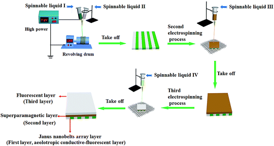 |
| | Fig. 1 Device diagram and electro-spinning process for preparation of the sandwich-configurational composite film. | |
The contrastive samples were fabricated to illustrate the preponderance of the structure of JAEF/MF/LF sandwich-configurational composite film. The electro-spinning process and schematic diagrams of contrastive samples are presented in Table S1.† Moreover, the constituents of spinnable liquids, spinnerets and electro-spinning conditions for fabricating the contrastive samples are also systematically summed up in Table S2.†
Characterization
The characterization methods are described in the ESI† section.
Results and discussion
Phase analysis
The phase compositions of the Fe3O4 NPs and JAEF/MF/LF sandwich-configurational composite film were studied by X-ray diffractometry (Fig. 2). XRD patterns of Fe3O4 NPs are in conformity with the cubic-structured Fe3O4 (PDF 89-0691) and characteristic peaks of other impurities do not exist, which indicates that Fe3O4 NPs are single and pure phase. When the aeolotropic conductive-fluorescent layer and the fluorescent layer of JAEF/MF/LF sandwich-configurational composite film face the X-ray source, characteristic diffraction peaks of Fe3O4 can be observed also. However, the reflection peaks of Fe3O4 are weaker because Fe3O4 NPs merely disperse throughout the middle layer of JAEF/MF/LF sandwich-configurational composite film and low contents of Fe3O4 NPs in the samples. The broad diffraction peaks at ca. 22° of the samples are also found, indicating the existence of amorphous substances, such as PMMA, PVP and rare earth complexes.
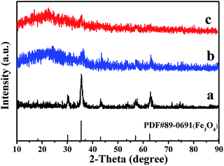 |
| | Fig. 2 XRD patterns of (a) Fe3O4 NPs, (b) the aeolotropic conductive-fluorescent layer and (c) the fluorescent layer of the JAEF/MF/LF sandwich-configurational composite film ([LI-3//LII-3]/LIII-2/LIV-3). | |
Morphological and structural analysis
As demonstrated in Fig. 3a, the intersecting surface of JAEF/MF/LF sandwich-configurational composite film can be clearly seen in scanning electron microscope (SEM) images with low magnification. It can be seen that the composite film is made up of three layers. Fig. 3b depicts the energy dispersive spectrum (EDS). The JAEF/MF/LF sandwich-configurational composite film is made of elements Fe, S, Eu, Tb, C, and O. Fig. 3c shows the SEM image of the Janus nanobelts. It is clear that all the width directions of these nanobelts in the aeolotropic conductive layer arrange upwards, almost without exception, due to the fact that this structure helps the nanobelts lay in a state of low energy and more stability onto the revolving drum. The average width of Janus nanobelts is 10.25 μm (Fig. 3d). The internal structure of a Janus nanobelt in the aeolotropic conductive layer can be expressly seen using the optical microscope (OM). As indicated in Fig. 3e, an obvious Janus structure can be observed, and one side of the Janus nanobelt is PANI/PMMA, which is dark-colored. In contrast, the other side is transparent Eu(BA)3phen/PMMA. In order to further examine the Janus structure of the nanobelt, EDS line-scan analysis was carried out (Fig. 3f), where the S and Eu elements delegate CSA doped PANI and Eu(BA)3phen, respectively. Elemental S only exists on one side, and elemental Eu merely appears in the other side of Janus nanobelt. Based on the analysis of the above results, we can surely conclude that aeolotropic conductive Janus nanobelts array film (namely the first layer) has been successfully prepared. SEM images (Fig. 3g and i) of the fluorescent layer and the superparamagnetic layer, which are composed of nanofibers, are also provided, respectively. The histograms of the diameter distribution of the nanofibers in fluorescent layer and superparamagnetic layer are severally demonstrated in Fig. 3h and j, and their average diameters are 630 nm and 480 nm, respectively.
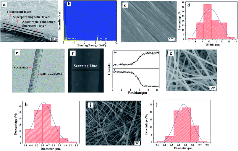 |
| | Fig. 3 SEM images of (a) intersecting surface, (c) aeolotropic conductive-fluorescent layer, (g) fluorescent layer and (i) superparamagnetic layer; (b) EDS spectrum of JAEF/MF/LF sandwich-configurational composite film; (d) histogram of width of Janus nanobelts in aeolotropic conductive-fluorescent layer; (e) OM image and (f) EDS line-scan analysis of single Janus nanobelt; (h) diameter distribution of nanofibers in fluorescent layer and (j) superparamagnetic layer. | |
The JAEF/[M–L]F two-layer composite film is also presented. The intersecting surface of the two-layer composite film is shown in Fig. S1a.† Fig. S1b† presents the SEM image of the superparamagnetic-fluorescent layer in the JAEF/[M–L]F two-layer composite film. The average diameter of the nanofibers in superparamagnetic-fluorescent layer is 390 nm (Fig. S1c†). Meanwhile, the first layers of JNEF/MF/LF, CNEF/MF/LF and CAEF/MF/LF sandwich-configurational composite film were examined also. The SEM images (Fig. S1d–f†) demonstrate the arrangement of nanobelts in these contrastive samples. The nanobelts in the JNEF/MF/LF and CNEF/MF/LF sandwich-configurational composite films are out of order (Fig. S1d and e†), but nanobelts in the CAEF/MF/LF sandwich-configurational composite film are ordered (Fig. S1f†).
Physical photos of the sandwich-configurational composite films are shown in Fig. 4. It is obvious that the aeolotropic conductive-fluorescent layer of the sandwich-configurational composite film is blackish green (Fig. 4b) owing to the existence of PANI in the aeolotropic conductive-fluorescent layer, and the fluorescent layer is white (Fig. 4d). It was found that the product (Fig. 4a) has a plain and neoteric three-layered structure: different layers show different colors due to the presence of different components. It can be seen in Fig. 4c and e that aeolotropic conductive-fluorescent layer and the fluorescent layer emit red fluorescence under 290 nm UV irradiation and green fluorescence under 314 nm UV illumination in darkness, respectively.
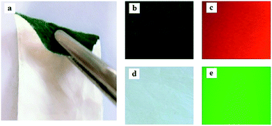 |
| | Fig. 4 Images: (a) a folded film, (b) the aeolotropic conductive-fluorescent layer, (c) red fluorescence emission under 290 nm excitation of the aeolotropic conductive-fluorescent layer in darkness (d) the fluorescent layer, and (e) green fluorescence emission under 314 nm excitation of the fluorescent layer in darkness. | |
Fluorescence performance
The fluorescence properties of sandwich-configurational composite film were further explored via modulating the contents of PANI and Fe3O4 NPs. Fig. 5 demonstrates the fluorescence spectra of the aeolotropic conductive-fluorescent layer (first layer) of the sandwich-configurational composite film. As shown in Fig. S2,† the optimum excitation (abbreviated as EX) wavelength is 290 nm. It can be found that the emission (abbreviated as EM) intensities of the aeolotropic conductive-fluorescent layer of the film decrease with the increase of PANI content. This phenomenon is caused by the light absorption of dark-colored PANI. The Eu(BA)3phen/PMMA sides of the Janus nanobelts absorb two kinds of EX light. The first is direct ultraviolet radiation on the Eu(BA)3phen/PMMA sides, and the second is ultraviolet light reflected or refracted on the PANI/PMMA sides. It is easy to infer that the former plays a major role in stimulating Eu(BA)3phen complexes in the Eu(BA)3phen/PMMA sides while the latter secondarily contributes to the EX process. As for the latter, since PANI absorbs ultraviolet light (<400 nm), as demonstrated by the UV-Vis absorption spectrum of PANI in Fig. 5c, more PANI leads to an increase in light absorption and weak reflection or refraction of ultraviolet light to Eu(BA)3phen/PMMA sides. Therefore, when more PANI is added, the EX light and EM light are partly weakened, resulting in the reduced fluorescence intensity of the aeolotropic conductive-fluorescent layer. On the contrary, the superparamagnetic layer (namely the second layer) has no effect on the fluorescence intensity of the aeolotropic conductive-fluorescent layer (Fig. 5b). This result is caused by the unique structure of the sandwich-configurational composite film. Because the three layers in the sandwich structure are independent of each other and it is difficult for the EX light to pass from the aeolotropic conductive-fluorescent layer to the superparamagnetic layer of the film, the dark-colored Fe3O4 NPs in the superparamagnetic layer cannot absorb the EX light and EM light, leading to no change in fluorescence intensity when the amount of Fe3O4 NPs increases. This result reveals the structural superiority of the sandwich-configurational composite film.
 |
| | Fig. 5 (a and b) EM spectra of the aeolotropic conductive-fluorescent layer (first layer) doped with different contents of PANI (a) and the superparamagnetic layer (second layer) doped with different ratios of Fe3O4 NPs (b); (c) UV-Vis absorbance spectrum of PANI. | |
As shown in Fig. S3,† the optimum EX wavelength is 314 nm for the fluorescent layer of the sandwich-configurational composite film. The fluorescence spectra of the fluorescent layer (third layer) of the sandwich-configurational composite film are displayed in Fig. 6. It is satisfactory to find that the fluorescence intensity of the sandwich-configurational composite film remained almost constant when the contents of PANI and Fe3O4 NPs were changed. The aeolotropic conductive-fluorescent layer and superparamagnetic layer have little effect on fluorescence properties of the fluorescent layer in the sandwich-configurational composite film, despite the changed contents of PANI in the aeolotropic conductive-fluorescent layer and the presence of Fe3O4 NPs in the superparamagnetic layer. The new findings result from the fact that the new-typed sandwich-configurational composite film high effectively separates the fluorescent layer from the aeolotropic conductive-fluorescent layer and the superparamagnetic layer, so that the two layers have almost no detrimental influence on the fluorescent layer.
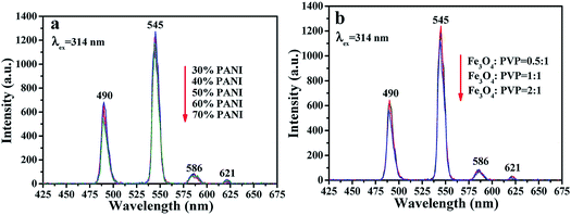 |
| | Fig. 6 (a and b) EM spectra of the fluorescent layer doped with different ratios of PANI in the aeolotropic conductive-fluorescent layer (a) and doped with different ratios of Fe3O4 NPs in the superparamagnetic layer (b). | |
The fluorescence properties of the first layer of JAEF/MF/LF sandwich-configurational composite film were also compared with those of the first layer of JNEF/MF/LF, CAEF/MF/LF and CNEF/MF/LF sandwich-configurational composite film, as displayed in Fig. 7. Compared with JAEF/MF/LF sandwich-configurational composite film, the EX and EM intensities of the JNEF/MF/LF sandwich-configurational composite film slightly decrease, while the fluorescent intensities of CAEF/MF/LF and CNEF/MF/LF sandwich-configurational composite films are very weak under the same compositions. Fig. 8 is the diagram showing the comparison of fluorescence characteristics of the four samples. As shown in Fig. 8, since the first layer of JAEF/MF/LF sandwich-configurational composite film is composed of highly aligned Janus nanobelts, the surface of the film is densified. The EX light is difficult to pass from the upper nanobelts to the lower ones, so the EM light generated is mainly emitted from the upper Janus nanobelts without reduction. As for the first layer of JNEF/MF/LF sandwich-configurational composite film demonstrated in Fig. 8, the Janus nanobelts are disordered, resulting in a loose surface of the film. In such case, part of the EX light will reach the lower Janus nanobelts through the voids of the loose upper Janus nanobelts, leading to the consequence that this part of EX light is weakened by the absorption of the upper Janus nanobelts. In the same way, the EM light is also absorbed when passing through the voids in the upper Janus nanobelts. As a result, the film has lower fluorescent intensity than JAEF/MF/LF sandwich-configurational composite film. For the same reason as stated above, the first layer of CAEF/MF/LF sandwich-configurational composite film has stronger fluorescent intensity than that of the first layer of CNEF/MF/LF sandwich-configurational composite film. As observed in Fig. 7A, the fluorescent intensity of the first layer of JAEF/MF/LF sandwich-configurational composite film and JNEF/MF/LF sandwich-configurational composite film are significantly higher than those of CAEF/MF/LF sandwich-configurational composite film and CNEF/MF/LF sandwich-configurational composite film. As for JAEF/MF/LF sandwich-configurational composite film and JNEF/MF/LF sandwich-configurational composite film, the constituent units are Janus nanobelts that effectively isolate Eu(BA)3phen complexes from PANI, resulting in greatly reduced absorption of EX light and EM light by PANI. Composite nanobelts are building units of CAEF/MF/LF sandwich-configurational composite film and CNEF/MF/LF sandwich-configurational composite film, in which the uniform distribution of the Eu(BA)3phen and PANI leads to the consequence that the dark-colored PANI strongly absorbs and weakens the EX light and the EM light. From the above analysis, it is found that JAEF/MF/LF sandwich-configurational composite film has the highest fluorescent intensity compared with the three contrastive samples. Hence, we can reasonably conclude that the structures of nanobelts and films significantly affect the fluorescent intensity, and Janus nanobelt array composite film has better performance than other contrastive samples. We also explored the EM spectra of the fluorescent layer of the JAEF/MF/LF, JNEF/MF/LF, CAEF/MF/LF and CNEF/MF/LF sandwich-configurational composite film. It can be seen from Fig. 7B that the fluorescent property of the fluorescent layer is not affected by the change of the first layer. It can be concluded that three layers in the sandwich structure are independent of each other, and the EX light is hard to pass through the fluorescent layer to the superparamagnetic layer and first layer of the film, leading to the result that the fluorescent layer is not affected by other layers.
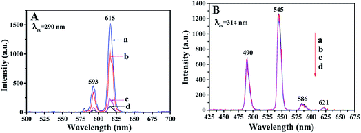 |
| | Fig. 7 EM spectra of (A) the first layer and (B) the fluorescent layer of (a) JAEF/MF/LF, (b) JNEF/MF/LF, (c) CAEF/MF/LF and (d) CNEF/MF/LF sandwich-configurational composite film. | |
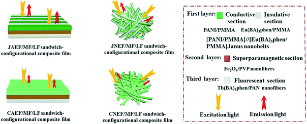 |
| | Fig. 8 Schematic of the EX light and EM light in JAEF/MF/LF, JNEF/MF/LF, CAEF/MF/LF and CNEF/MF/LF sandwich-configurational composite film. | |
Besides, to further demonstrate the advantages of the unique structure of the JAEF/MF/LF sandwich-configurational composite film, fluorescence studies of the JAEF/MF/LF sandwich-configurational composite film and JAEF/[M–L]F two-layer composite film were performed. Compared with the fluorescent layer of the JAEF/MF/LF sandwich-configurational composite film, JAEF/[M–L]F two-layer composite film (superparamagnetic-fluorescent layer) exhibits extremely weak emissions of Tb3+. Fig. 9 shows the emission spectra of the JAEF/MF/LF sandwich-configurational composite film (fluorescent layer) and JAEF/[M–L]F two-layer composite film (superparamagnetic-fluorescent layer). In order to explain these results, in Fig. 10 we present the schematic diagrams of the fluorescent properties of JAEF/MF/LF sandwich-configurational composite film and JAEF/[M–L]F two-layer composite film. Tb(BA)3phen of the JAEF/[M–L]F two-layer composite film directly contacts the dark-colored Fe3O4 NPs which strongly absorb EX and EM light, resulting in a serious decrease in fluorescent intensity. On the other hand, many researches have shown that elemental Fe can cause fluorescence quenching of RE fluorescent compounds, which also leads to a decrease of fluorescence intensity.43 On the contrary, the fluorescent layer is separated from the superparamagnetic layer and the aeolotropic conductive-fluorescent layer in the JAEF/MF/LF sandwich-configurational composite film. The fluorescent intensity of the fluorescent layer is almost unaffected by the other two layers. It can be seen from the above analysis that the JAEF/MF/LF sandwich-configurational composite film possesses better fluorescence properties than the JAEF/[M–L]F two-layer composite film, strongly implying that the sandwich-configurational composite film is better than the two-layer composite film for constructing peculiar materials with multi-functionalities.
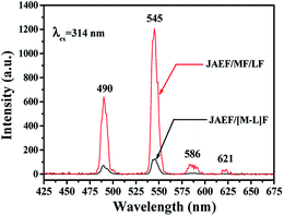 |
| | Fig. 9 Emission spectra of the fluorescent layer in JAEF/MF/LF sandwich-configurational composite film and the superparamagnetic-fluorescent layer in JAEF/[M–L]F two-layer composite film. | |
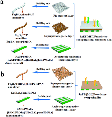 |
| | Fig. 10 Schematic of the EX light and EM light of (a) the fluorescent layer in JAEF/MF/LF sandwich-configurational composite film and (b) the superparamagnetic-fluorescent layer in JAEF/[M–L]F two-layer composite film. | |
Electrical conduction analysis
The electrical properties of the layers containing PANI of the JAEF/MF/LF sandwich-configurational composite film and four contrastive samples were researched. For all specimens, the mass percentages of Eu(BA)3phen to PMMA, Tb(BA)3phen to PAN and the mass ratio of Fe3O4 to PVP were fixed at 15%, 15% and 1![[thin space (1/6-em)]](https://www.rsc.org/images/entities/char_2009.gif) :
:![[thin space (1/6-em)]](https://www.rsc.org/images/entities/char_2009.gif) 1, respectively. Moreover, the mass percentages of PANI to PMMA were varied from 30% to 70%. In the two orthogonal orientations on the horizontal surface of the film, the length orientation (conductive orientation) and width orientation (insulative orientation) of the nanobelts were labeled as A and B, respectively. The test methods for the films are shown in Fig. 11. Two pieces of soldering tin (1 × 0.45 cm2) as electrodes were attached to the sample (cut into 1 cm × 1 cm) via conductive adhesive. The distance between two pieces of soldering tin was 0.1 cm. The electrical conductances of JAEF/MF/LF sandwich-configurational composite film (aeolotropic conductive-fluorescent layer) and four contrastive samples are listed in Table 5. It is reported that the charge transport capacity provided by connective conductive network is a key factor for the conduction of PANI.44 For the JAEF/MF/LF sandwich-configurational composite film, it can be seen from Table 5 that the higher is the content of PANI in the Janus nanobelts in aeolotropic conductive-fluorescent layer, the higher electrical conductance of A orientation can be obtained, while the conductance changes within B orientation is very small. Accordingly, by regulating the ratio of PANI to PMMA, the conductance of the product can be adjusted so that the aeolotropic ability also can be tailored. The diagrammatic sketch of the conductive mechanism of JAEF/MF/LF sandwich-configurational composite film with various amounts of PANI in the Janus nanobelts array layer (aeolotropic conductive-fluorescent layer) is displayed in Fig. 12. Electrons can move unhindered along the length orientation of the Janus nanobelts when current is generated in the film. As the PANI content increases, the increase in conductance is due to the formation of a more continuous PANI network structure which results in a more effective charge transport. Moreover, with an increase of PANI content, the green color of the conductive side of Janus nanobelts becomes deeper. The conductance along with the width orientation still retains ca. −10 orders of magnitude, regardless of how much the PANI content increases. As seen in Table 5, for the JAEF/MF/LF sandwich-configurational composite film, with the change of Fe3O4 NPs content in the superparamagnetic layer, the conductance of the film does not change significantly. Fig. 13 displays the diagrammatic sketch of the conduction mechanism of JAEF/MF/LF sandwich-configurational composite film with various ratios of Fe3O4. Owing to the same content of PANI and the same structure in the aeolotropic conductive-fluorescent layer, they have similar conductance and the same color in the aeolotropic conductive-fluorescent layer of the film. For the fluorescent layer, the conductance value cannot be acquired (lower than the detection limit), which means that the fluorescent layer is insulated. Hence, the peculiarity of each layer is mutually independent, which is ascribed to the exceptional sandwich structure of the film.
1, respectively. Moreover, the mass percentages of PANI to PMMA were varied from 30% to 70%. In the two orthogonal orientations on the horizontal surface of the film, the length orientation (conductive orientation) and width orientation (insulative orientation) of the nanobelts were labeled as A and B, respectively. The test methods for the films are shown in Fig. 11. Two pieces of soldering tin (1 × 0.45 cm2) as electrodes were attached to the sample (cut into 1 cm × 1 cm) via conductive adhesive. The distance between two pieces of soldering tin was 0.1 cm. The electrical conductances of JAEF/MF/LF sandwich-configurational composite film (aeolotropic conductive-fluorescent layer) and four contrastive samples are listed in Table 5. It is reported that the charge transport capacity provided by connective conductive network is a key factor for the conduction of PANI.44 For the JAEF/MF/LF sandwich-configurational composite film, it can be seen from Table 5 that the higher is the content of PANI in the Janus nanobelts in aeolotropic conductive-fluorescent layer, the higher electrical conductance of A orientation can be obtained, while the conductance changes within B orientation is very small. Accordingly, by regulating the ratio of PANI to PMMA, the conductance of the product can be adjusted so that the aeolotropic ability also can be tailored. The diagrammatic sketch of the conductive mechanism of JAEF/MF/LF sandwich-configurational composite film with various amounts of PANI in the Janus nanobelts array layer (aeolotropic conductive-fluorescent layer) is displayed in Fig. 12. Electrons can move unhindered along the length orientation of the Janus nanobelts when current is generated in the film. As the PANI content increases, the increase in conductance is due to the formation of a more continuous PANI network structure which results in a more effective charge transport. Moreover, with an increase of PANI content, the green color of the conductive side of Janus nanobelts becomes deeper. The conductance along with the width orientation still retains ca. −10 orders of magnitude, regardless of how much the PANI content increases. As seen in Table 5, for the JAEF/MF/LF sandwich-configurational composite film, with the change of Fe3O4 NPs content in the superparamagnetic layer, the conductance of the film does not change significantly. Fig. 13 displays the diagrammatic sketch of the conduction mechanism of JAEF/MF/LF sandwich-configurational composite film with various ratios of Fe3O4. Owing to the same content of PANI and the same structure in the aeolotropic conductive-fluorescent layer, they have similar conductance and the same color in the aeolotropic conductive-fluorescent layer of the film. For the fluorescent layer, the conductance value cannot be acquired (lower than the detection limit), which means that the fluorescent layer is insulated. Hence, the peculiarity of each layer is mutually independent, which is ascribed to the exceptional sandwich structure of the film.
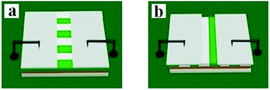 |
| | Fig. 11 Schematic for the conductance test of samples: (a) parallel orientation test and (b) perpendicular orientation test of the nanobelts in the JAEF/MF/LF sandwich-configurational composite film. | |
Table 5 Conductance of the JAEF/MF/LF sandwich-configurational composite film with different amounts of PANI and various ratios of Fe3O4 to PVP and the four contrastive samples
| Samples |
Conductance (S) |
A/B ratios |
Aeolotropism degree |
| A |
B |
| JAEF/MF/LF sandwich-configurational composite film [LI-1//LII-3]/LIII-2/LIV-3 (30% PANI) |
7.82 × 10⁻⁶ |
2.63 × 10⁻¹⁰ |
2.97 × 10⁴ |
Medium |
| JAEF/MF/LF sandwich-configurational composite film [LI-2//SII-3]/LIII-2/LIV-3 (40% PANI) |
6.43 × 10⁻⁵ |
2.58 × 10⁻¹⁰ |
2.49 × 10⁵ |
Strong |
| JAEF/MF/LF sandwich-configurational composite film [LI-3//LII-3]/LIII-2/LIV-3 (50% PANI) |
6.85 × 10⁻⁴ |
3.24 × 10⁻¹⁰ |
2.11 × 10⁶ |
Strong |
| JAEF/MF/LF sandwich-configurational composite film [LI-4//LII-3]/LIII-2/SIV-3 (60% PANI) |
8.62 × 10⁻³ |
2.75 × 10⁻¹⁰ |
3.13 × 10⁷ |
Very strong |
| JAEF/MF/LF sandwich-configurational composite film [LI-5//LII-3]/LIII-2/SIV-3 (70% PANI) |
7.62 × 10⁻² |
3.36 × 10⁻¹⁰ |
2.27 × 10⁸ |
Very strong |
JAEF/MF/LF sandwich-configurational composite film [LI-3//LII-3]/LIII-1/LIV-3 (Fe3O4![[thin space (1/6-em)]](https://www.rsc.org/images/entities/char_2009.gif) : :![[thin space (1/6-em)]](https://www.rsc.org/images/entities/char_2009.gif) PVP = 0.5 PVP = 0.5![[thin space (1/6-em)]](https://www.rsc.org/images/entities/char_2009.gif) : :![[thin space (1/6-em)]](https://www.rsc.org/images/entities/char_2009.gif) 1) 1) |
6.34 × 10⁻⁴ |
2.89 × 10⁻¹⁰ |
2.19 × 10⁶ |
Strong |
JAEF/MF/LF sandwich-configurational composite film [LI-3//LII-3]/LIII-3/SIV-3 (Fe3O4![[thin space (1/6-em)]](https://www.rsc.org/images/entities/char_2009.gif) : :![[thin space (1/6-em)]](https://www.rsc.org/images/entities/char_2009.gif) PVP = 2 PVP = 2![[thin space (1/6-em)]](https://www.rsc.org/images/entities/char_2009.gif) : :![[thin space (1/6-em)]](https://www.rsc.org/images/entities/char_2009.gif) 1) 1) |
5.89 × 10⁻⁴ |
2.64 × 10⁻¹⁰ |
2.23 × 10⁶ |
Strong |
| JNEF/MF/LF sandwich-configurational composite film ([LI-3//LII-3]/LIII-2/LIV-3) |
3.05 × 10⁻⁴ |
2.96 × 10⁻⁴ |
1.03 |
None |
| CAEF/MF/LF sandwich-configurational composite film (LV/LIII-2/LIV-3) |
2.58 × 10⁻⁷ |
8.31 × 10⁻¹⁰ |
310 |
Weak |
| CNEF/MF/LF sandwich-configurational composite film (LV/LIII-2/LIV-3) |
2.68 × 10⁻⁷ |
2.92 × 10⁻⁷ |
0.92 |
None |
| JAEF/[M–L]F two-layer composite film ([LI-3//LII-3]/LVI) |
5.73 × 10⁻⁴ |
3.05 × 10⁻¹⁰ |
1.88 × 10⁶ |
Strong |
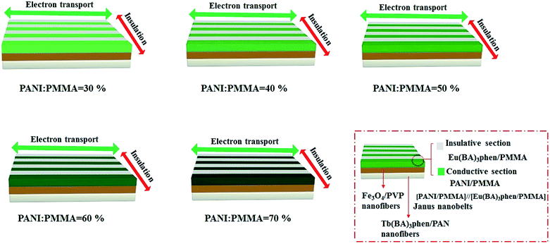 |
| | Fig. 12 Schematic of conductive mechanism and color variation with different amounts of PANI in the aeolotropic conductive-fluorescent layer of the JAEF/MF/LF sandwich-configurational composite film. | |
 |
| | Fig. 13 Schematic of conductive mechanism with various ratios of Fe3O4 to PVP in the superparamagnetic layer of the JAEF/MF/LF sandwich-configurational composite film. | |
It is also shown in Table 5 that the JAEF/MF/LF sandwich-configurational composite film and the JAEF/[M–L]F two-layer composite film possess almost the same electrical properties, but the conductance of their conductive orientation is higher than that of JNEF/MF/LF, CAEF/MF/LF and CNEF/MF/LF sandwich-configurational composite film with the same ingredients. The conduction mechanism diagrams of the JAEF/MF/LF sandwich-configurational composite film and four contrastive samples are shown in Fig. 14. In the Janus nanobelts array layer (first layer) of the JAEF/MF/LF sandwich-configurational composite film, the Janus nanobelts are arrayed in the same orientation, causing the flow orientation of current to stay fixed. On the contrary, because Janus nanobelts in the JNEF/MF/LF sandwich-configurational composite film are not ordered, the orientation of current flow is disordered. Under these conditions, all orientations of the film possess similar electrical conduction, resulting in a decrease in conductance in a specific orientation. CAEF/MF/LF and the CNEF/MF/LF sandwich-configurational composite films exhibit observably lower conductance owing to the presence of an insulating material, (Eu(BA)3phen/PMMA), in the PANI/Eu(BA)3phen/PMMA composite nanobelts, leading to blocking the construction of a continuous conductive network. The JAEF/[M–L]F two-layer composite film has almost the same electrical properties as the JAEF/MF/LF sandwich-configurational composite film because insulating materials such as Tb(BA)3phen, Fe3O4, PVP and PAN are dispersed in the superparamagnetic-fluorescent layer. The conductance ratios (namely A/B values) between the two orientations for different samples are also listed in Table 5 in detail. The conductance ratios between A and B are almost the same when the PANI content is fixed. When the content of Fe3O4 varies, the conductance does not change significantly. Nevertheless, with the increase of PANI contents, the A/B ratios markedly increase and the level of conductive aeolotropism also increases. In other words, tunable conductive aeolotropism can be realized. Most important of all, the A/B ratios reach up to ca. 108 times when the mass percentage of PANI is settled at 70%. As far as we know, this is the highest reported value for the nanobelts array films.
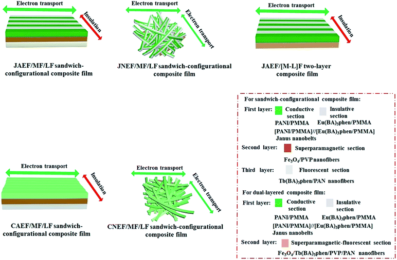 |
| | Fig. 14 Conductive schematic diagrams of the JAEF/MF/LF sandwich-configurational composite film along with four contrastive samples. | |
In order to find the outstanding aeolotropic conduction of the JAEF/MF/LF sandwich-configurational composite film, conductance values of contrastive samples were also measured, using the same methods (depicted in Fig. 11). The current direction of the JAEF/MF/LF sandwich-configurational composite film is settled such that the direction parallel to the length of the nanobelts is conductive and the vertical orientation is insulative; therefore, the film exhibits high conductance ratio. That is to say, this type of film displays strong aeolotropism ([LI-3//LII-3]/LIII-2/LIV-3, 50% PANI, A/B ≈ 106). The JNEF/MF/LF sandwich-configurational composite film exhibits no electrically conductive aeolotropism, as seen in Table 5, because the film has electrical conduction in all orientations. The conductance ratio of A/B (two perpendicular orientations) is ca. 1. Although the CAEF/MF/LF sandwich-configurational composite film possesses aeolotropism, the aeolotropism is relatively weak (A/B ≈ 310). The interfaces between the nanobelts can serve as the insulative media, but the insulation is not strong enough, leading to weak aeolotropism. For the CNEF/MF/LF sandwich-configurational composite film, both high conductance and aeolotropism (A/B ≈ 0.92) are not acquired. The above results fully demonstrate that the JAEF/MF/LF sandwich-configurational composite film possesses the highest degree of aeolotropism compared with the three sandwich-configurational contrastive samples.
Superparamagnetic properties
The hysteresis loops of the JAEF/MF/LF sandwich-configurational composite film containing different mass ratios of Fe3O4 NPs and the JAEF/[M–L]F two-layer composite film are demonstrated in Fig. 15, and Table 6 summarizes their saturation magnetizations.
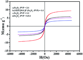 |
| | Fig. 15 Hysteresis loops of JAEF/MF/LF sandwich-configurational composite film of different Fe3O4 NPs mass ratios and JAEF/[M–L]F two-layer composite film. | |
Table 6 Saturation magnetization of JAEF/MF/LF sandwich-configurational composite film of different Fe3O4 NPs mass ratios and JAEF/[M–L]F two-layer composite film
| Samples (emu g−1) |
Saturation magnetization (Ms) |
JAEF/MF/LF [LI-3//LII-3]/LIII-3/SIV-3 (Fe3O4![[thin space (1/6-em)]](https://www.rsc.org/images/entities/char_2009.gif) : :![[thin space (1/6-em)]](https://www.rsc.org/images/entities/char_2009.gif) PVP = 2 PVP = 2![[thin space (1/6-em)]](https://www.rsc.org/images/entities/char_2009.gif) : :![[thin space (1/6-em)]](https://www.rsc.org/images/entities/char_2009.gif) 1) 1) |
9.3 |
JAEF/MF/LF [LI-3//LII-3]/LIII-2/SIV-3 (Fe3O4![[thin space (1/6-em)]](https://www.rsc.org/images/entities/char_2009.gif) : :![[thin space (1/6-em)]](https://www.rsc.org/images/entities/char_2009.gif) PVP = 1 PVP = 1![[thin space (1/6-em)]](https://www.rsc.org/images/entities/char_2009.gif) : :![[thin space (1/6-em)]](https://www.rsc.org/images/entities/char_2009.gif) 1) 1) |
5.1 |
JAEF/MF/LF [LI-3//LII-3]/LIII-1/SIV-3 (Fe3O4![[thin space (1/6-em)]](https://www.rsc.org/images/entities/char_2009.gif) : :![[thin space (1/6-em)]](https://www.rsc.org/images/entities/char_2009.gif) PVP = 0.5 PVP = 0.5![[thin space (1/6-em)]](https://www.rsc.org/images/entities/char_2009.gif) : :![[thin space (1/6-em)]](https://www.rsc.org/images/entities/char_2009.gif) 1) 1) |
3.4 |
JAEF/[M–L]F (Fe3O4![[thin space (1/6-em)]](https://www.rsc.org/images/entities/char_2009.gif) : :![[thin space (1/6-em)]](https://www.rsc.org/images/entities/char_2009.gif) PVP = 1 PVP = 1![[thin space (1/6-em)]](https://www.rsc.org/images/entities/char_2009.gif) : :![[thin space (1/6-em)]](https://www.rsc.org/images/entities/char_2009.gif) 1) 1) |
5.8 |
With the increase of Fe3O4 NPs content, the saturation magnetization of the JAEF/MF/LF sandwich-configurational composite film increases from 3.4 to 9.3 emu g−1, indicating that the composite film possesses tunable superparamagnetism. The superparamagnetic performance of the JAEF/MF/LF sandwich-configurational composite film {[LI-3//LII-3]/LIII-2/LIV-3} is similar to that of the JAEF/[M–L]F two-layer composite film due to the fact that they have the same quantity of Fe3O4 NPs in theory. The diagrammatic sketch of the JAEF/MF/LF sandwich-configurational composite film, containing different mass ratios of Fe3O4 NPs to PVP, is revealed in Fig. 16. The color of the superparamagnetic layer becomes darker with the increase of Fe3O4 NPs content. This is because Fe3O4 NPs are black, and the presence of more Fe3O4 NPs contributes to the darker color of the superparamagnetic layer in the JAEF/MF/LF sandwich-configurational composite film.
 |
| | Fig. 16 Schematic of the JAEF/MF/LF sandwich-configurational composite film with various mass ratios of Fe3O4 NPs to PVP. | |
Conclusions
A brand-new sandwich-configurational composite film has been successfully fabricated for the first time using a facile three-step electrospinning technology. The aeolotropic conductive-fluorescent layer (first layer) of the sandwich-configurational composite film is composed of orderly arranged Janus nanobelts which consist of a conductive side and an insulating side, making the film possess electrically conductive aeolotropism. The degree of conduction aeolotropism on the aeolotropic conductive-fluorescent layer can be adjusted by regulating the content of PANI, and the conductivity of conductive orientation is about 108 orders of magnitude higher than that of the insulating orientation. Disordered nanofibers severally form superparamagnetic and fluorescent layers containing Fe3O4 NPs and Eu(BA)3phen, achieving excellent superparamagnetic and fluorescent properties. The superparamagnetic properties of the composite film are tailored by varying the content of Fe3O4 NPs. Moreover, it is very satisfying to find that the fluorescent layer exhibits excellent fluorescence properties which are not influenced by Fe3O4 NPs and PANI. Microscopic partition and macroscopic partition simultaneously exist in the 2D sandwich-configurational composite film, and a highly efficient combination of microscopic partition with macroscopic partition is actualized in the novel film. Microscopic partition, actualized in the Janus nanobelt and used as a building unit, ensures that the film possesses high conductive aeolotropism, while the macroscopic partition, realized in the whole 2D film, guarantees no mutual interference among electricity, superparamagnetism and fluorescence. Macroscopically, electrically conductive aeolotropism, superparamagnetism and fluorescence are highly integrated, meanwhile, the three functions are also mutually independent in the novel 2D film. Namely, the three functions are highly integrated as well as absolutely mutually independent. The neoteric sandwich-configurational composite film also can be popularized to assemble various three functions to realize multi-functionalization without mutual pernicious interferences among single functions. This neoteric sandwich-configurational composite film has a great potential for nanodevice construction, microwave absorption and other fields. Even more importantly, the design idea and preparative means presented in this work are of great significance towards new-typed aeolotropic conductive films with multifunctionality.
Conflicts of interest
There are no conflicts of interest to declare.
Acknowledgements
This study was financially supported by National Natural Science Foundation of China (51573023, 50972020), Natural Science Foundation of Jilin Province (20170101101JC, 20180520011JH), Industrial Technology Research and Development Project of Jilin Province Development and Reform Commission (2017C052-4), Science and Technology Research Planning Project of the Education Department of Jilin Province during the 13th five-year plan period (JJKH20170608KJ, JJKH20181122KJ), and Innovative Foundation (XJJLG-2017-04) and Youth Foundation (XQNJJ-2016-01, XQNJJ-2017-17) of Changchun University of Science and Technology.
Notes and references
- S. W. Li, Y. Y. Feng, P. Long, C. Q. Qin and W. Feng, J. Mater. Chem., 2017, 5, 5068–5075 CAS.
- S. Fujii, Y. Suzuki, J. Kawamata and R. Tsunashima, J. Mater. Chem. C, 2015, 3, 7153–7158 RSC.
- H. Kang, D. Kim and S. Baik, Phys. Chem. Chem. Phys., 2014, 16, 18759–18764 RSC.
- Y. W. Chen, Y. H. Guo, S. Batra, E. Wang, Y. P. Wang, X. Q. Liu, Y. M. Wang and M. Cakmak, Nanoscale, 2015, 7, 14636–14642 RSC.
- C. Mao, J. R. Huang, Y. T. Zhu, W. Jiang, Q. X. Tang and X. J. Ma, J. Phys. Chem. Lett., 2013, 4, 43–47 CrossRef CAS PubMed.
- Q. H. Tang, Y. F. Wang, M. Zou and W. J. Guo, Nanoscale, 2018, 10, 4344–4353 RSC.
- J. R. Huang, Y. T. Zhu, W. Jiang, J. H. Yin, Q. X. Tang and X. D. Yang, ACS Appl. Mater. Interfaces, 2014, 6, 1754–1758 CrossRef CAS PubMed.
- Q. L. Ma, J. X. Wang, X. T. Dong, W. S. Yu and G. X. Liu, Adv. Funct. Mater., 2015, 25, 2436–2443 CrossRef CAS.
- Y. T. Geng, P. Zhang, Q. T. Wang, Y. X. Liu and K. Pan, J. Mater. Chem. A, 2017, 5, 5390–5396 RSC.
- J. Y. Liu, Q. L. Ma, J. Tian, X. Xi, D. Li, X. T. Dong, W. S. Yu, X. L. Wang, J. X. Wang and G. X. Liu, RSC Adv., 2018, 8, 22887–22896 RSC.
- Q. L. Ma, W. S. Yu, X. T. Dong, J. X. Wang and G. X. Liu, Nanoscale, 2014, 6, 2945–2952 RSC.
- Z. J. Wang, Q. L. Ma, X. T. Dong, D. Li, X. Xi, W. S. Yu, J. X. Wang and G. X. Liu, ACS Appl. Mater. Interfaces, 2016, 8, 26226–26234 CrossRef CAS PubMed.
- Y. W. Liu, Q. L. Ma, M. Yang, X. T. Dong, Y. Yang, J. X. Wang, W. S. Yu and G. X. Liu, Chem. Eng. J., 2016, 284, 831–840 CrossRef CAS.
- C. Y. Wen, H. Y. Xie, Z. L. Zhang, L. L. Wu, J. Hu, M. Tang, M. Wu and D. W. Pang, Nanoscale, 2016, 8, 12406–12429 RSC.
- S. L. Gai, P. P. Yang, C. X. Li, W. X. Wang, Y. L. Dai, N. Niu and J. Lin, Adv. Funct. Mater., 2010, 20, 1166–1172 CrossRef CAS.
- P. Li, S. P. Zhang, K. Li, J. X. Wang, M. L. Liu, X. N. Gu and Y. B. Fan, J. Mater. Chem. A, 2018, 6, 4952–4962 CAS.
- C. C. Liu, X. H. Jiang, Y. Y. Zhao, W. W. Jiang, Z. M. Zhang and L. M. Yu, Electrochim. Acta, 2017, 231, 53–60 CrossRef CAS.
- K. L. Zhou, H. Wang, J. T. Jiu, J. B. Liu, H. Yan and K. Suganuma, Chem. Eng. J., 2018, 345, 290–299 CrossRef CAS.
- X. B. Liu, Z. P. Wu and Y. H. Yin, Chem. Eng. J., 2017, 323, 330–339 CrossRef CAS.
- T. K. Gupta, B. P. Singh, R. B. Mathur and S. R. Dhakate, Nanoscale, 2013, 6, 842–851 RSC.
- X. Xi, W. S. Yu, Q. L. Ma, D. Li, X. T. Dong, J. X. Wang and G. X. Liu, RSC Adv., 2018, 8, 31608–31617 RSC.
- Q. H. Li, S. L. Zhou, S. W. Wang, X. C. Zhu, L. J. Zhang, Z. J. Feng, L. P. Guo, F. H. Wang and Y. Wei, Dalton Trans., 2013, 42, 2861–2869 RSC.
- B. Yan, L. M. Zhao, X. M. Wang and Y. Zhao, RSC Adv., 2011, 1, 1064–1071 RSC.
- D. Liu and Z. G. Wang, RSC Adv., 2012, 2, 10085–10090 RSC.
- L. B. Fan, Q. L. Ma, J. Tian, D. Li, X. Xi, X. T. Dong, W. S. Yu, J. X. Wang and G. X. Liu, J. Mater. Sci., 2018, 53, 2290–2302 CrossRef CAS.
- R. X. Gao, X. R. Mu, J. J. Zhang and Y. H. Tang, J. Mater. Chem. A, 2014, 2, 783–792 CAS.
- J. C. Feng, S. R. Yu, J. Li, T. Mo and P. Li, Chem. Eng. J., 2016, 286, 216–222 CrossRef CAS.
- S. M. Zhu, J. C. Fu, H. L. Li, L. Zhu, Y. Hu, W. X. Xia, X. X. Zhang, Y. Peng and J. L. Zhang, ACS Nano, 2018, 12, 3442–3448 CrossRef CAS PubMed.
- F. Chen, C. Li, Y. J. Zhu, X. Y. Zhao, B. Q. Lu and J. Wu, Biomater. Sci., 2013, 1, 1074–1081 RSC.
- C. Luo, X. X. Wang, J. Q. Wang and K. Pan, Compos. Sci. Technol., 2016, 133, 97–103 CrossRef CAS.
- X. Xi, J. X. Wang, X. T. Dong, Q. L. Ma, W. S. Yu and G. X. Liu, Chem. Eng. J., 2014, 254, 259–267 CrossRef CAS.
- N. Lv, Z. G. Wang, W. Z. Bi, G. M. Li, J. L. Zhang and J. Z. Ni, J. Mater. Chem. A, 2016, 4, 4402–4409 RSC.
- N. Lv, J. L. Zhang, G. M. Li, X. Wang and J. Z. Ni, J. Phys. Chem. C, 2017, 121, 11926–11931 CrossRef CAS.
- P. Zhang, C. L. Shao, X. H. Li, M. Y. Zhang, X. Zhang, C. Y. Su, N. Lu, K. X. Wang and Y. C. Liu, Phys. Chem. Chem. Phys., 2013, 25, 10453–10458 RSC.
- Y. C. Chou, C. L. Shao, X. H. Li, C. Y. Su, H. C. Xu, M. Y. Zhang, P. Zhang, X. Zhang and Y. C. Liu, Appl. Surf. Sci., 2013, 285, 509–516 CrossRef CAS.
- H. Ji, R. Zhao, N. Zhang, C. X. Jin, X. F. Lu and C. Wang, NPG Asia Mater., 2018, 10, 749–760 CrossRef CAS.
- M. Q. Chi, S. H. Chen, M. X. Zhong, C. Wang and X. F. Lu, Chem. Commun., 2018, 54, 5827–5830 RSC.
- X. Xi, Q. L. Ma, X. T. Dong, D. Li, W. S. Yu, J. X. Wang and G. X. Liu, ChemPlusChem, 2018, 83, 108–116 CrossRef CAS.
- Q. L. Ma, J. X. Wang, X. T. Dong, W. S. Yu, G. X. Liu and J. Xu, J. Mater. Chem., 2012, 22, 14438–14442 RSC.
- Z. J. Li, Z. L. Hou, W. L. Song, X. D. Liu, W. Q. Cao, X. H. Shao and M. S. Cao, Nanoscale, 2016, 8, 10415–10424 RSC.
- L. L. Gao, X. Chen, H. Gao and S. B. Zhang, Mater. Sci. Eng., A, 2010, 527, 5115–5121 CrossRef.
- J. Tian, Q. L. Ma, X. T. Dong, M. Yang, Y. Yang, J. X. Wang, W. S. Yu and G. X. Liu, J. Mater. Sci.: Mater. Electron., 2015, 26, 8413–8420 CrossRef CAS.
- X. Shen and B. Yan, RSC Adv., 2014, 5, 6752–6757 RSC.
- X. B. Li, Q. L. Ma, J. Tian, X. Xi, D. Li, X. T. Dong, W. S. Yu, X. L. Wang, J. X. Wang and G. X. Liu, Nanoscale, 2017, 9, 18918–18930 RSC.
Footnote |
| † Electronic supplementary information (ESI) available. See DOI: 10.1039/c8na00351c |
|
| This journal is © The Royal Society of Chemistry 2019 |
Click here to see how this site uses Cookies. View our privacy policy here.  Open Access Article
 *,
Qianli
Ma
*,
Guixia
Liu
*,
Qianli
Ma
*,
Guixia
Liu
 and
Jinxian
Wang

![[thin space (1/6-em)]](https://www.rsc.org/images/entities/char_2009.gif) :
:![[thin space (1/6-em)]](https://www.rsc.org/images/entities/char_2009.gif) PVP (mass ratio)
PVP (mass ratio)![[thin space (1/6-em)]](https://www.rsc.org/images/entities/char_2009.gif) :
:![[thin space (1/6-em)]](https://www.rsc.org/images/entities/char_2009.gif) 1
1![[thin space (1/6-em)]](https://www.rsc.org/images/entities/char_2009.gif) :
:![[thin space (1/6-em)]](https://www.rsc.org/images/entities/char_2009.gif) 1
1![[thin space (1/6-em)]](https://www.rsc.org/images/entities/char_2009.gif) :
:![[thin space (1/6-em)]](https://www.rsc.org/images/entities/char_2009.gif) 1
1![[thin space (1/6-em)]](https://www.rsc.org/images/entities/char_2009.gif) :
:![[thin space (1/6-em)]](https://www.rsc.org/images/entities/char_2009.gif) 1 (named spinnable liquid V); the other two spinnable liquids for superparamagnetic layer and fluorescent layer were spinnable liquids LIII-2 and LIV-3. The spinnable liquid for superparamagnetic-fluorescent layer of JAEF/[M–L]F two-layer composite film was prepared by mixing equivoluminal spinnable liquids LIII-2 and LIV-3 (named spinnable liquid VI), and spinnable liquids for Janus nanobelts array layer of JAEF/[M–L]F two-layer composite film were spinnable liquids LI-3, LII-3. Table S2† summarizes the constituents of spinnable liquids in detail.
1 (named spinnable liquid V); the other two spinnable liquids for superparamagnetic layer and fluorescent layer were spinnable liquids LIII-2 and LIV-3. The spinnable liquid for superparamagnetic-fluorescent layer of JAEF/[M–L]F two-layer composite film was prepared by mixing equivoluminal spinnable liquids LIII-2 and LIV-3 (named spinnable liquid VI), and spinnable liquids for Janus nanobelts array layer of JAEF/[M–L]F two-layer composite film were spinnable liquids LI-3, LII-3. Table S2† summarizes the constituents of spinnable liquids in detail.


![[thin space (1/6-em)]](https://www.rsc.org/images/entities/char_2009.gif) :
:![[thin space (1/6-em)]](https://www.rsc.org/images/entities/char_2009.gif) 1, respectively. Moreover, the mass percentages of PANI to PMMA were varied from 30% to 70%. In the two orthogonal orientations on the horizontal surface of the film, the length orientation (conductive orientation) and width orientation (insulative orientation) of the nanobelts were labeled as A and B, respectively. The test methods for the films are shown in Fig. 11. Two pieces of soldering tin (1 × 0.45 cm2) as electrodes were attached to the sample (cut into 1 cm × 1 cm) via conductive adhesive. The distance between two pieces of soldering tin was 0.1 cm. The electrical conductances of JAEF/MF/LF sandwich-configurational composite film (aeolotropic conductive-fluorescent layer) and four contrastive samples are listed in Table 5. It is reported that the charge transport capacity provided by connective conductive network is a key factor for the conduction of PANI.44 For the JAEF/MF/LF sandwich-configurational composite film, it can be seen from Table 5 that the higher is the content of PANI in the Janus nanobelts in aeolotropic conductive-fluorescent layer, the higher electrical conductance of A orientation can be obtained, while the conductance changes within B orientation is very small. Accordingly, by regulating the ratio of PANI to PMMA, the conductance of the product can be adjusted so that the aeolotropic ability also can be tailored. The diagrammatic sketch of the conductive mechanism of JAEF/MF/LF sandwich-configurational composite film with various amounts of PANI in the Janus nanobelts array layer (aeolotropic conductive-fluorescent layer) is displayed in Fig. 12. Electrons can move unhindered along the length orientation of the Janus nanobelts when current is generated in the film. As the PANI content increases, the increase in conductance is due to the formation of a more continuous PANI network structure which results in a more effective charge transport. Moreover, with an increase of PANI content, the green color of the conductive side of Janus nanobelts becomes deeper. The conductance along with the width orientation still retains ca. −10 orders of magnitude, regardless of how much the PANI content increases. As seen in Table 5, for the JAEF/MF/LF sandwich-configurational composite film, with the change of Fe3O4 NPs content in the superparamagnetic layer, the conductance of the film does not change significantly. Fig. 13 displays the diagrammatic sketch of the conduction mechanism of JAEF/MF/LF sandwich-configurational composite film with various ratios of Fe3O4. Owing to the same content of PANI and the same structure in the aeolotropic conductive-fluorescent layer, they have similar conductance and the same color in the aeolotropic conductive-fluorescent layer of the film. For the fluorescent layer, the conductance value cannot be acquired (lower than the detection limit), which means that the fluorescent layer is insulated. Hence, the peculiarity of each layer is mutually independent, which is ascribed to the exceptional sandwich structure of the film.
1, respectively. Moreover, the mass percentages of PANI to PMMA were varied from 30% to 70%. In the two orthogonal orientations on the horizontal surface of the film, the length orientation (conductive orientation) and width orientation (insulative orientation) of the nanobelts were labeled as A and B, respectively. The test methods for the films are shown in Fig. 11. Two pieces of soldering tin (1 × 0.45 cm2) as electrodes were attached to the sample (cut into 1 cm × 1 cm) via conductive adhesive. The distance between two pieces of soldering tin was 0.1 cm. The electrical conductances of JAEF/MF/LF sandwich-configurational composite film (aeolotropic conductive-fluorescent layer) and four contrastive samples are listed in Table 5. It is reported that the charge transport capacity provided by connective conductive network is a key factor for the conduction of PANI.44 For the JAEF/MF/LF sandwich-configurational composite film, it can be seen from Table 5 that the higher is the content of PANI in the Janus nanobelts in aeolotropic conductive-fluorescent layer, the higher electrical conductance of A orientation can be obtained, while the conductance changes within B orientation is very small. Accordingly, by regulating the ratio of PANI to PMMA, the conductance of the product can be adjusted so that the aeolotropic ability also can be tailored. The diagrammatic sketch of the conductive mechanism of JAEF/MF/LF sandwich-configurational composite film with various amounts of PANI in the Janus nanobelts array layer (aeolotropic conductive-fluorescent layer) is displayed in Fig. 12. Electrons can move unhindered along the length orientation of the Janus nanobelts when current is generated in the film. As the PANI content increases, the increase in conductance is due to the formation of a more continuous PANI network structure which results in a more effective charge transport. Moreover, with an increase of PANI content, the green color of the conductive side of Janus nanobelts becomes deeper. The conductance along with the width orientation still retains ca. −10 orders of magnitude, regardless of how much the PANI content increases. As seen in Table 5, for the JAEF/MF/LF sandwich-configurational composite film, with the change of Fe3O4 NPs content in the superparamagnetic layer, the conductance of the film does not change significantly. Fig. 13 displays the diagrammatic sketch of the conduction mechanism of JAEF/MF/LF sandwich-configurational composite film with various ratios of Fe3O4. Owing to the same content of PANI and the same structure in the aeolotropic conductive-fluorescent layer, they have similar conductance and the same color in the aeolotropic conductive-fluorescent layer of the film. For the fluorescent layer, the conductance value cannot be acquired (lower than the detection limit), which means that the fluorescent layer is insulated. Hence, the peculiarity of each layer is mutually independent, which is ascribed to the exceptional sandwich structure of the film.

![[thin space (1/6-em)]](https://www.rsc.org/images/entities/char_2009.gif) :
:![[thin space (1/6-em)]](https://www.rsc.org/images/entities/char_2009.gif) PVP = 0.5
PVP = 0.5![[thin space (1/6-em)]](https://www.rsc.org/images/entities/char_2009.gif) :
:![[thin space (1/6-em)]](https://www.rsc.org/images/entities/char_2009.gif) 1)
1)![[thin space (1/6-em)]](https://www.rsc.org/images/entities/char_2009.gif) :
:![[thin space (1/6-em)]](https://www.rsc.org/images/entities/char_2009.gif) PVP = 2
PVP = 2![[thin space (1/6-em)]](https://www.rsc.org/images/entities/char_2009.gif) :
:![[thin space (1/6-em)]](https://www.rsc.org/images/entities/char_2009.gif) 1)
1)


![[thin space (1/6-em)]](https://www.rsc.org/images/entities/char_2009.gif) :
:![[thin space (1/6-em)]](https://www.rsc.org/images/entities/char_2009.gif) PVP = 2
PVP = 2![[thin space (1/6-em)]](https://www.rsc.org/images/entities/char_2009.gif) :
:![[thin space (1/6-em)]](https://www.rsc.org/images/entities/char_2009.gif) 1)
1)![[thin space (1/6-em)]](https://www.rsc.org/images/entities/char_2009.gif) :
:![[thin space (1/6-em)]](https://www.rsc.org/images/entities/char_2009.gif) PVP = 1
PVP = 1![[thin space (1/6-em)]](https://www.rsc.org/images/entities/char_2009.gif) :
:![[thin space (1/6-em)]](https://www.rsc.org/images/entities/char_2009.gif) 1)
1)![[thin space (1/6-em)]](https://www.rsc.org/images/entities/char_2009.gif) :
:![[thin space (1/6-em)]](https://www.rsc.org/images/entities/char_2009.gif) PVP = 0.5
PVP = 0.5![[thin space (1/6-em)]](https://www.rsc.org/images/entities/char_2009.gif) :
:![[thin space (1/6-em)]](https://www.rsc.org/images/entities/char_2009.gif) 1)
1)![[thin space (1/6-em)]](https://www.rsc.org/images/entities/char_2009.gif) :
:![[thin space (1/6-em)]](https://www.rsc.org/images/entities/char_2009.gif) PVP = 1
PVP = 1![[thin space (1/6-em)]](https://www.rsc.org/images/entities/char_2009.gif) :
:![[thin space (1/6-em)]](https://www.rsc.org/images/entities/char_2009.gif) 1)
1)


