 Open Access Article
Facile synthesis of a nanoporous sea sponge architecture in a binary metal oxide
Avijit
Biswal
a,
Prasanna
Panda
bc,
Zhong-Tao
Jiang
 d,
Bankim
Tripathy
bc and
Manickam
Minakshi
 *d
*d
aDepartment of Chemistry, College of Engineering & Technology, Bhubaneswar 751029, India
bCSIR-Institute of Minerals and Materials Technology, Bhubaneswar 751013, India
cAcademy of Scientific and Innovative Research, Ghaziabad, 201 002, India
dSchool of Engineering and Information Technology, Murdoch University, WA 6150, Australia. E-mail: minakshi@murdoch.edu.au
First published on 5th March 2019
Abstract
A novel galvanostatic electrochemical technique has been employed to synthesize a cobalt–nickel mixed oxide, a binary metal oxide, via a two-step route involving electrodeposition followed by calcination. A diaphragm cell was used for the electro-deposition of the binary hydroxide at room temperature in which the electrolyte comprises a nitrate and/or sulphate bath of the corresponding metal ions at pH 4. The electrodeposited product was calcined at 300 °C to obtain the desired oxide material. The formation of the binary metal oxide has been confirmed by X-ray diffraction analysis. The scanning electron microscopy images associated with energy dispersive analysis (EDS) suggest the formation of a nanoporous sea sponge architecture consisting of an interconnected array of nanosheets aligned perpendicular to each other. The elemental mapping analysis of the binary oxide illustrated the uniformity in the distribution of Co and Ni in the composite material. The TEM image shows that binary oxides are nanocrystalline materials. A nitrogen adsorption–desorption study supports the pore size distribution behaviour of the synthesized material. The hybrid capacitor based on the binary metal oxide cathode and activated carbon anode displayed a capacitive behaviour with a capacitance of 76 F g−1 at a current rate of 2 mA with 98% efficiency after 1000 cycles. Due to the unique interconnected porous network and the role of binary cations, Co–Ni oxide exhibits superior electrochemical behaviour. The synthesis of binary oxides forming various morphologies, such as hexagonal, flower-shape, and sea sponge has been discussed.
1. Introduction
In recent years with the development of renewable energy, clean and highly efficient electrochemical energy storage devices have become crucial, as it will be more important in the future. Among various energy storage devices, electrochemical supercapacitors have drawn great attention due to their attractive features such as fast recharge, long-term cycling stability, and low maintenance cost but with limited energy density. A lot of research efforts have been devoted to improving the energy performance of supercapacitors through synthesizing efficient electrode materials possessing a high capacitance for their use in emerging power delivery systems. In the last decade, the rare-earth element based RuO2 had been considered as a promising electrode material due to its high theoretical specific capacitance, but its cost and toxic nature restrict its wide use.1,2 Thus, recently, transition metal oxides/hydroxides have drawn attention as a conventional and inexpensive electrode material with the aim of achieving a high specific capacitance with improved rate capability and long cycle life.2–7 Among the various transition metal oxides, nickel and cobalt oxides have made a significant contribution as electrode materials for the supercapacitor device irrespective of some of their limitations. The low conductivity and limited cycling stability are considered as major drawbacks for metal oxides or hydroxides. Nevertheless, a Co-based oxide has long been considered as a promising electrode material for its high theoretical capacity and excellent pseudocapacitive properties, while nickel oxide with a lower theoretical capacity is less expensive than its Co counterpart. Therefore, various attempts have been made to overcome the drawbacks of NiO by coupling with other transition metal oxides8–12 and carbon-based materials13 to improve its performance. Consequently, this resulted in the significant contribution made by mixed transition metal oxides owing to their high energy density and specific capacitance.14–18 The mixed transition metal oxide can be formed either by the combination of two transition metal oxides or a transition metal oxide along with a carbon-containing material in stoichiometric or non-stoichiometric compositions. These mixed transition metal oxides are evolving as promising electrode materials for all forms of energy storage devices.19–21 The reported mixed transition metal oxides perform exceptionally well with a high specific capacity, exceeding those of carbon/graphite based electrode materials. This is due to the complex chemical compounds of the mixed oxides. Especially, binary transition metal oxides due to the multiple oxidation states present in their cations take part in electrochemical processes, giving better capacity and cycle life stability than monometallic transition metal oxides.22–24 Mixed transition metal oxides exhibit significantly higher electrical conductivity than monometallic transition metal oxides, as they need relatively low activation energy for electron transfer between cations.17,25 Among the range of available transition metal cations, it is worth developing metal oxides of nickel combined with cobalt to utilize the synergistic effect of both metal ions26 resulting in high electrical conductivity to realize a high rate capability.Various methods including sol–gel,27,28 potentiostatic electrodeposition,17,29 the hydrothermal method,22,30 and co-precipitation26,31 have been reported for the synthesis of Co–Ni binary oxides. However, galvanostatic electrodeposition methods are more versatile owing to the simplicity of the process and possibility of tailoring the material to the need. However, a study on the synthesis of nanomaterials using galvanostatic electrodeposition has not been widely reported. The electrochemical method is an eco-friendly, cost-effective novel method as the deposition process can be tweaked through the applied current as compared to the previously reported methods. Additionally, the galvanostatic electrochemical deposition produces nanostructured particles with controlled characteristics, namely, the particle size, crystallographic orientation, mass, thickness, and morphology by adjusting the operating conditions and bath chemistry.32 A high surface area of the desired product can be obtained by calcining the electrodeposited porous binary metal hydroxide materials. Such a type of binary metal oxide has been synthesized and examined for energy storage viability.
A hybrid capacitor comprising a binary transition metal oxide as a battery-type faradaic electrode coupled with activated carbon as a capacitor-type electrode to bridge the gap between rechargeable batteries and supercapacitors has been reported here with enhanced energy density. Electrode materials with a porous architecture facilitate easy electron transport for faradaic reactions at the electrode–electrolyte interface leading to high energy density for SCs.33 Hence, the material properties of the synthesized product provide sufficient electroactive sites to play a crucial role in supercapacitor cell performance.
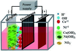
In this work, electrolytic production of Co–Ni binary oxides from aqueous solutions of two sets of electrolytes containing nitrate and sulphate in a two-compartment diaphragm cell (see Scheme 1) has been carried out using a novel galvanostatic electrodeposition at room temperature with subsequent calcination at 300 °C. Very little work appears to have been done on the electrodeposition of binary metal hydroxides followed by calcination to obtain binary metal oxides having various morphologies. The porous architecture of highly pure Ni–Co binary oxides with a hierarchical sea sponge-like morphology is obtained by this facile two-step method. The morphologies of the material are observed to vary from hexagonal to flower shaped and then to a sea sponge architecture while varying the electrolytic bath. The obtained materials were tested as electrodes for supercapacitors ensuring that features like fast charge and discharge rates, and high cycling stability have been met as a primary pre-requisite.
2. Experimental
2.1 Preparation of metal hydroxides and binary metal oxides by electrodeposition
All the chemicals used in this study were of pure analytical grade and were used as received without any further purification. A two-compartment diaphragm cell (shown in Scheme 1) was used for the electrodeposition process. A current was supplied from a constant current DC source (Aplab rectifier) in galvanostatic mode. Pure cobalt hydroxides and/or mixed Co–Ni hydroxides were deposited from two sets of an electrolyte containing nitrate and sulphate aqueous salt solution. Deposition of cobalt hydroxide and mixed Co–Ni hydroxides was carried out from nitrate medium containing 30 g dm−3 Co(NO3)2·7H2O and 30 g dm−3 Co(NO3)2·7H2O + 30 g dm−3 Ni(NO3)2 respectively. A sulphate bath composed of 30 g dm−3 CoSO4·7H2O + 10 g dm−3 NaNO3 was used for cobalt hydroxide deposition. NaNO3 was used as the supporting electrolyte in sulphate medium.The cathodic reduction of Co2+ to Co(OH)2 and/or Ni2+ to Ni(OH)2 was carried out on a stainless steel (SS) cathode placed in parallel to an iridium oxide coated titanium (IrO2–Ti) anode at a cathodic current density of 200 A m−2. All experiments were carried out at room temperature for 2 h. The electrodeposited materials were removed from the cathode after the deposition and washed thoroughly with deionized water before drying in an oven. Subsequently, the resultant product was finally dried and cooled in a desiccator and subjected to physical tests such as X-ray diffraction (XRD) and other microscopy analyses.
2.2 Calcination step and sample labelling
Monometallic and binary hydroxides were calcined at 300 °C to convert them to their respective oxides. Then the materials were subjected to physical and electrochemical characterization. Cobalt hydroxide samples prepared from a nitrate and sulphate bath were labeled CH-nitrate and CH-sulphate respectively. Similarly, Co–Ni mixed hydroxides deposited from a nitrate bath were labeled CNH-nitrate. After calcination, these samples were labeled CO-nitrate, CO-sulphate, and CNO-nitrate, respectively.2.3 Materials characterization
Various physicochemical characterization techniques were carried out to identify the phase, surface morphology and porous nature of the prepared monometallic oxides and mixed oxides. Phase analysis was carried out using a Phillips powder diffractometer (PAN ANALYTICAL PW 1830) using Cu Kα radiation. Nitrogen adsorption–desorption studies were carried out using a Micromeritics Tristar II surface area and porosity analyser. Before analysing, the samples were degassed at 100 °C overnight. The surface morphology of the samples was determined using field emission scanning electron microscopy (FESEM, ZEISS SUPRA 55) together with energy dispersive analysis. High-resolution transmission electron microscopy images and selected area diffraction patterns of the binary metal oxide were obtained using a JEOL JEM 2100 operated at 200 kV.2.4 Electrochemical characterization
For electrochemical measurements, the electrode was prepared by mixing the active material (metal oxide), carbon black and polyvinylidene fluoride (PVDF) in a 75![[thin space (1/6-em)]](https://www.rsc.org/images/entities/char_2009.gif) :
:![[thin space (1/6-em)]](https://www.rsc.org/images/entities/char_2009.gif) 15
15![[thin space (1/6-em)]](https://www.rsc.org/images/entities/char_2009.gif) :
:![[thin space (1/6-em)]](https://www.rsc.org/images/entities/char_2009.gif) 10 wt% ratio. All ingredients were mixed in N-methyl-2-pyrrolidone (NMP, 250 μL) to make a slurry which was coated on a small piece of graphite sheet with a coating area of 1 cm2. The coated electrode was then dried on a hot plate (at 40 °C for an hour) to evaporate the solvent before any electrochemical testing.
10 wt% ratio. All ingredients were mixed in N-methyl-2-pyrrolidone (NMP, 250 μL) to make a slurry which was coated on a small piece of graphite sheet with a coating area of 1 cm2. The coated electrode was then dried on a hot plate (at 40 °C for an hour) to evaporate the solvent before any electrochemical testing.
The electrochemical behaviour of metal oxide materials was investigated by cyclic voltammetry and impedance spectroscopy using an SP-150, Bio-Logic instrument and galvanostatic charge–discharge and rate capability measurements were carried out by using a Battery Analyser (MTI corp, USA) operated using a battery testing system (BTS). Electrochemical behaviour of both monometallic and binary metal oxides was investigated by using three-electrode cells with 2 M NaOH as the electrolyte and Pt wire and Hg/HgO as the counter and reference electrodes, respectively, over a potential range from 0.0–0.6 V at different sweep rates. Galvanostatic charge/discharge curves in the potential range of 0.2–1.6 V at various current densities were recorded. Electrochemical impedance spectroscopy (EIS) was carried out with an amplitude of 5 mV over a frequency range of 10 MHz to 700 kHz at an open circuit potential. The specific capacitance (SC) and energy density (E) of the device were calculated using the following equations:
| SC (F g−1) = IΔt/mΔV | (1) |
| E (W h kg−1) = E = 1/2SCΔV2 | (2) |
| m+/m− = (SC− × ΔV−)/(SC+ × ΔV+) | (3) |
3. Results and discussion
3.1 Electrodeposition
During the electrolysis of Co(NO3)2 solution, nitrate ions from the bath play a vital role in the deposition of cobalt hydroxide.34 Initially, on applying a potential to the electrochemical diaphragm cell, nitrate ions get reduced to nitrite and hydroxyl ions are formed. The process during reduction is given as:| NO3− + H2O + 2e− → NO2− + 2OH− (aq.) | (4) |
Hydroxyl groups formed via electrochemical reduction are expected to react with Co2+ ions present in the electrolyte. As a result, cobalt hydroxide is deposited on the substrate according to the following reaction:
| Co2+ + 2OH− → Co(OH)2 | (5) |
Nickel is also deposited in a similar manner
| Ni2+ + 2OH− → Ni(OH)2 | (6) |
| Electrolyte | Current efficiency (CE) (%) | Energy consumption (EC) (kW h kg−1) |
|---|---|---|
| 30 g dm−3 Co(NO3)2 | 98 | 2.24 |
| 30 g dm−3 CoSO4 + 10 g dm−3 NaNO3 | 100 | 2.20 |
| 30 g L−1 CoCl2 + 10 g L−1 NaNO3 | 100 | 2.11 |
| Electrolyte | Current efficiency (CE) (%) | Energy consumption (EC) (kW h kg−1) |
|---|---|---|
| 30 g dm−3 CoSO4 + 5 g dm−3 NaNO3 | 86 | 2.86 |
| 30 g dm−3 CoSO4 + 10 g dm−3 NaNO3 | 100 | 2.20 |
| 30 g dm−3 CoSO4 + 20 g dm−3 NaNO3 | 100 | 2.22 |
![[E with combining low line]](https://www.rsc.org/images/entities/b_char_0045_0332.gif) ffect of the binary electrolyte.
Basically, as our aim is to synthesize cobalt–nickel binary hydroxide, electrolytic baths containing nickel nitrate and nickel sulphate along with cobalt nitrate and cobalt sulphate were chosen. The result (in Table 3) revealed that the sulphate bath leads to consumption of less energy than the nitrate bath with about 100% current efficiency in both the cases. This may be due to the presence of the supporting electrolyte which increases the conductance of the solution resulting in a decrease in voltage of the deposition process. However, in this work, we have investigated the mixed cobalt–nickel oxide deposited from the nitrate bath only.
ffect of the binary electrolyte.
Basically, as our aim is to synthesize cobalt–nickel binary hydroxide, electrolytic baths containing nickel nitrate and nickel sulphate along with cobalt nitrate and cobalt sulphate were chosen. The result (in Table 3) revealed that the sulphate bath leads to consumption of less energy than the nitrate bath with about 100% current efficiency in both the cases. This may be due to the presence of the supporting electrolyte which increases the conductance of the solution resulting in a decrease in voltage of the deposition process. However, in this work, we have investigated the mixed cobalt–nickel oxide deposited from the nitrate bath only.
| Electrolyte | Current efficiency (CE) (%) | Energy consumption (EC) (kW h kg−1) |
|---|---|---|
| 30g dm−3 Co(NO3)2 + 30 g dm−3 Ni(NO3)2 | 100 | 1.99 |
| 30 g dm−3 CoSO4 + 30 g dm−3 NiSO4 + 10 g dm−3 NaNO3 | 100 | 1.96 |
3.2 Structural analysis of metal hydroxides and binary metal oxides
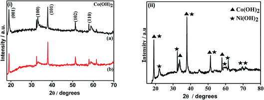
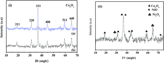
The X-ray diffraction patterns of the electrodeposited samples and subsequent to calcination are shown in Fig. 1 and 2, respectively. The cobalt hydroxides deposited from nitrate and sulphate baths prior to calcination (CH-nitrate, CH-sulphate) shown in Fig. 1i have diffraction peaks at 2θ values with the respective (h k l) indices, 19.00 (001), 33.080 (100), 37.89 (101), 51.34 (102), and 57.92 (110) without any second phase as an impurity. This indicates that the electrodeposited product in both the cases of an electrolytic bath (such as nitrate and sulphate) can be well indexed to a pure phase of Co(OH)2 having a hexagonal crystal structure (JCPDS card no. 30-0443). Fig. 1(ii) shows the X-ray diffraction pattern of the electrodeposited material from a bath containing cobalt nitrate and nickel nitrate mixed solution prior to calcination. The XRD pattern revealed the formation of mixed phases of Co(OH)2 and Ni(OH)2 with the hexagonal crystal structure (JCPDS card no. 30-0443, 74-2075) indicating that the binary metal hydroxides have been formed as expected in the presence of two electrolytes.XRD analysis of the cobalt hydroxides (CO-nitrate, CO-sulphate) after calcination was carried out and the results are shown in Fig. 2(i) a and b. The XRD pattern revealed the formation of cubic cobalt oxide (Co3O4) (JCPDS card no. 76-1802) for both the samples. The diffraction peaks at angles (2θ) of about 19.175, 31.225, 36.775, 44.725 and 59.425 are assigned to the (111), (220), (311), (102) and (110) planes of the Co3O4 crystal lattice, respectively. Fig. 2(ii) shows the X-ray diffraction pattern of binary cobalt–nickel oxide (CNO-nitrate) with diffraction peaks of 19.185, 31.245, 36.776, 44.375 and 59.442 (JCPDS card no. 76-1802) corresponding to the Co3O4 crystal lattice. However diffraction peaks at about 36.975, 43.375, 72.075 and at 30.825 and 64.775 correspond to the different planes of NiO and Ni2O3 crystal lattices (JCPDS card no. 47-1049) respectively. These results suggest the fact that the binary oxide materials contain the phases of Co3O4 along with different phases of nickel such as NiO and Ni2O3. The mean crystallite size (L) of the CNO-nitrate sample was calculated using the Debye–Scherrer equation (eqn (7)) and found to be 23.40 nm.
L = Kλ/(β![[thin space (1/6-em)]](https://www.rsc.org/images/entities/char_2009.gif) cos cos![[thin space (1/6-em)]](https://www.rsc.org/images/entities/char_2009.gif) θ) θ) | (7) |
3.3 FE-SEM and TEM analyses: hexagonal, flower-shape, and sea sponge morphologies
The microstructures and the surface morphologies of the cobalt oxides (CO-nitrate and CO-sulphate) and cobalt–nickel mixed oxide (CNO-nitrate) samples are shown in Fig. 3. Fig. 3 shows the typical SEM images of metal oxides and the observed significant difference in the morphology during the electrodeposition process. The results revealed that the CO-nitrate sample shows hexagonal plate-like crystals with a maximum size of 1 μm along with various smaller hexagonal plate-like crystallites within the nanosize range.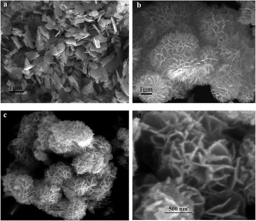 | ||
| Fig. 3 FE-SEM images of (a) CO-nitrate, (b) CO-sulphate, and CNO-nitrate samples at (c) lower and (d) higher magnifications. | ||
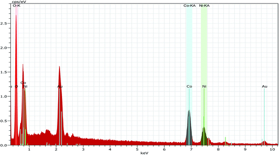
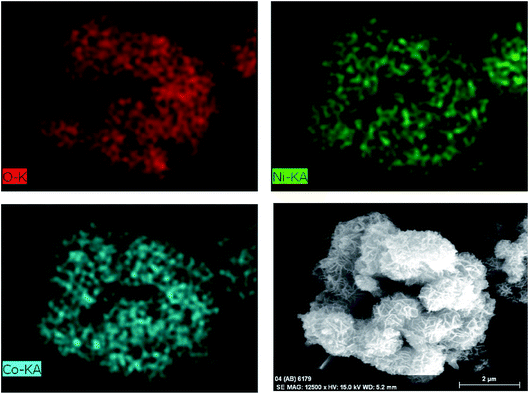
Fig. 3b shows the SEM image of the CO-sulphate sample with quite different morphological changes indicating a flower-like porous structure. The SEM images of binary metal oxides under different magnifications, shown in Fig. 3c and d, exhibit a sea sponge-like architecture highly porous in nature. On a close view, it was observed that each spongy architecture is composed of nanoplate like crystallites with a fairly uniform thickness, giving highly porous texture to the crystal. Thus, an interconnected porous network may lead to a high surface area resulting in an excellent performance for electrochemical applications due to easy ionic/electronic transport.35Fig. 4 shows the corresponding energy dispersive analysis of the CNO-nitrate sample. The relative intensities of the EDS spectra showed that the mixed oxide material consists of an approximately equal metal molar ratio of cobalt to nickel ions in the crystal lattice. The elemental mapping analysis of the CNO-nitrate sample is illustrated in Fig. 5 and the area of the analysed region is shown in the FE-SEM image. It is clearly seen that the two elements Co and Ni have been distributed uniformly on each crystal along with oxygen. Generally, the brighter the colour, the higher is the elemental concentration of Ni and Co. The unique structure of the resultant binary oxide with the homogeneity of the metal atom distribution aids the increase of the specific capacitance and energy density.
The transmission electron microscopy (TEM) images of the binary metal oxide (CNO-nitrate) are shown in Fig. 6. The bright field images at different magnifications (Fig. 6a and b) show individual particles with a crystallite size in the range 10–25 nm, which is consistent with the values of the XRD data obtained using Scherrer's formula. Fig. 6c shows striations illustrating the nanocrystallinity of the binary oxide material. The corresponding selected area diffraction pattern (SADP in Fig. 6d) is not a representative of the whole material, however, it shows bright spots in the diffraction rings confirming the crystallinity. The d-values obtained from the SADP pattern are in accordance with the results of the X-ray diffraction.
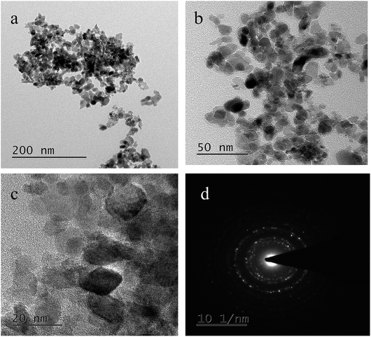 | ||
| Fig. 6 Transmission electron microscopy (TEM) images of the CNO-nitrate sample (a–c) at different magnifications and (d) the corresponding selected area diffraction pattern (SADP). | ||
3.4 Pore-size analysis
To examine the pore size distribution of the metal oxides, nitrogen gas-sorption measurement was performed for CO-nitrate, CO-sulphate, and CNO-nitrate samples. Fig. 7 shows the nitrogen adsorption–desorption isotherms and the corresponding Barrett–Joyner–Halenda (BJH) pore-size distribution curves of CO-nitrate, CO-sulphate, and CNO-nitrate samples. The N2 physisorption isotherms of all the samples show a type-IV isotherm with an H2-type hysteresis loop indicating the mesoporous nature of the materials.36 Cobalt–nickel mixed oxide i.e. CNO-nitrate showed a shift in the loop to a higher relative pressure approaching P/P0 = 0.99, signifying the fact that a large number of mesopores are present compared to that of the pure cobalt oxide samples (CO-nitrate, CO-sulphate) and hence the higher surface area of 62 m2 g−1.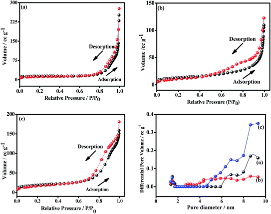 | ||
| Fig. 7 Nitrogen adsorption–desorption and pore-size distribution plots of (a) CO-nitrate, (b) CO-sulphate, and (c) CNO-nitrate samples. | ||
The BJH pore-size distribution curve showed a significant difference between the CNO-nitrate, CO-nitrate and CO-sulphate samples. CO-nitrate and CO-sulphate showed a pore-size distribution curve centered at about 8.63 nm; however, the pore-size distribution curve shifted to a higher pore volume and centered at about 9.31 nm for the CNO-nitrate sample, suggesting that a larger pore size is required for easy transfer of the electrolyte through the mixed oxide material matrix. Based on the above results, CNO-nitrate may correspond to an excellent candidate, as the mesopores reduce the diffusion distance for electrolyte ion transport while enhancing the adsorption of ions during the electrochemical energy storage.2,35
3.5 Electrochemical characterisation
| Electrodes | R s | R ct | W | C dl | CPE |
|---|---|---|---|---|---|
| Ω cm2 | Ω cm2 | Ω cm2 s−1/2 | F cm−2 | 10−3 Ω−1 cm−2 s | |
| CO-nitrate | 213.7856 | 28.5683 | 5.87 | 0.61 | 6.72 |
| CO-sulphate | 173.1564 | 15.3276 | 4.53 | 0.60 | 4.32 |
| CNO nitrate (before cycling) | 103.9819 | 9.5274 | 2.72 | 0.63 | 3.68 |
| CNO nitrate (after cycling | 79.5307 | 6.3926 | 1.73 | 0.45 | 1.46 |
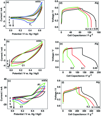
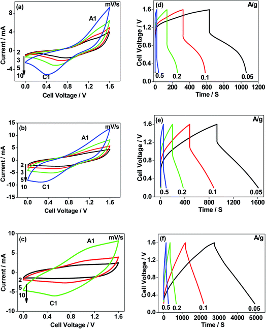
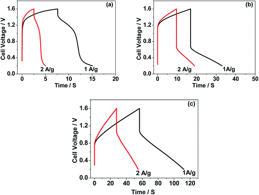
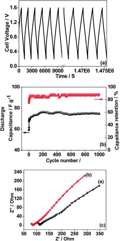
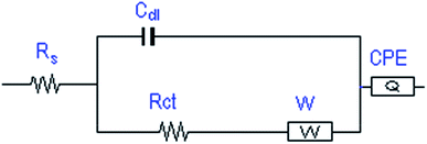
The CNO nitrate hybrid capacitor (shown in Fig. 9f) delivers a specific capacitance of 76 F g−1 with an energy density of 75 W h kg−1 at a power density of 125 W kg−1. The electrochemical performance of the binary metal oxide reported in this work compares well with similar materials reported in the literature like Co3O4 (57 F g−1),40 NiCo2O4 (64 F g−1),33 Co–Ni oxides (82 F g−1),1 CoMoO4 (25 F g−1),41 NiMoO4 (100 F g−1),42 and other ternary metal oxides.43 Furthermore, the device constructed using the binary metal oxide exhibited long-term stability, reproducing a similar linear charge–discharge curve after 1000 cycles (Fig. 11a) which is a typical requirement for a hybrid capacitor suitable for any practical applications. The cycling stability test conducted by means of repeated charge–discharge over 1000 cycles at a current density of 0.1 A g−1 revealed (Fig. 11b) excellent stability with a capacitance retention of 98%. During the initial ten cycles, the discharge capacitance was low (60 F g−1) and then the capacitance was increased to 76 F g−1 during 100 cycles and then stabilized thereon. This could be attributed to the activation of mesopores occurring after a few cycles to provide an accessible area for charge accommodation. This is further confirmed by the Nyquist plots (in Fig. 11c) that compare the electrodes before and after cycling. The equivalent circuit for the Nyquist plots is shown in Fig. 12 and the fitting values are presented in Table 4. Both the plots (in Fig. 11c) were composed of a distorted semicircle in the high-frequency region and a linear part in the low-frequency region, illustrating a typical capacitive type behaviour. This is described by the parallel circuit of Rct (charge-transfer resistance) and Cdl (double layer capacitance) while Cp (pseudo capacitance) is for the steep inclined line, which is replaced by a constant phase element (CPE) while including the chemical properties of the metal oxides. The chemical diffusion impedance is referred to as the Warburg impedance (W).44 In both the high frequency and low frequency areas, the cycled CNO nitrate electrode exhibited low Rs (solution resistance of 79.53 Ω cm2) and Rct (diameter of the semicircle, 6.39 Ω cm2) values (tabulated in Table 4), indicating the lower ion diffusion resistance due to the nanoporous network (as illustrated in the TEM images, Fig. 6) for the binary metallic oxides with a sea-sponge architecture. The slope line at the low-frequency region for the cycled electrode is steeper implying the capacitive like behaviour ascribed to the low mass transfer resistivity of the electrolyte3 within the nanoporous structure of CNO nitrate. In the case of CO-nitrate and CO-sulphate electrodes, the intrinsic resistance of the electrode (Rs) and kinetic resistance (Rct and CPE) to ion transfer at the interface between the metal oxide surface and electrolyte are relatively higher (see Table 4) than those for CNO nitrate. Therefore, the surface electrochemical reaction (Rs, Rct), formation of the double layer at the interface (Cdl), and sequential electron transfer from the surface to the bulk (W and CPE) all appear to be favourable for the CNO nitrate electrode which confirms the experimental values of higher discharge specific capacitance.
4. Conclusions
Facile synthesis of a sea sponge architecture in the binary metal oxide, Co–Ni mixed oxide, is achieved by electrodeposition using a diaphragm cell comprising a nitrate and sulphate bath with a pH of 4 followed by calcination. A maximum current efficiency of 100% was obtained from the galvanostatic electrodeposition. After calcination, monometallic and binary metal oxide electrodes showed various morphologies and the bath chemistry played a crucial role in determining the overall capacitive behaviours. The morphology and pore size distribution of the obtained metal oxides could easily be tweaked with the operating conditions. The electrochemical tests demonstrate that CNO nitrate exhibits superior characteristics with a specific discharge capacitance of 250 F g−1 (three-electrode configuration) and 76 F g−1 (two-electrode configuration) and excellent rate capability delivering an energy density of 75 W h kg−1 at a power density of 125 W kg−1, with long-term cyclability of 98% retention of its initial capacitance. The results establish that the hybrid capacitor using CNO nitrate as the positive electrode and activated carbon as the negative electrode can work at 1.6 V and is a potential candidate for supercapacitor applications.Conflicts of interest
There are no conflicts to declare.Acknowledgements
One of the authors (AB) would like to acknowledge the grant body, Technical Education Quality Improvement Program (TEQIP – III), Department of Higher Education, Government of India for funding this work.References
- J. Zhang, F. Liu, J. P. Cheng and X. B. Zhang, Binary Nickel-cobalt Oxides Electrode Materials for High-performance Supercapacitors: Influence of its Composition and Porous Nature, ACS Appl. Mater. Interfaces, 2015, 7, 17630–17640 CrossRef CAS PubMed.
- D. Dong, Y. Liu and J. Li, Co3O4 hollow polyhedrons as bifunctional electrocatalysts for reduction and evolution reactions of oxygen, Part. Part. Syst. Charact., 2016, 33, 887–895 CrossRef CAS.
- G. Wang, L. Zhang and J. Zhang, A Review of Electrode Materials for Electrochemical Supercapacitors, Chem. Soc. Rev., 2012, 41, 797–828 RSC.
- H. Chen, L. Hu, Y. Yan, R. Che, M. Chen and L. Wu, One-Step Fabrication of Ultrathin Porous Nickel Hydroxide-Manganese Dioxide Hybrid Nanosheets for Supercapacitor Electrodes with Excellent Capacitive Performance, Adv. Energy Mater., 2013, 3, 1636–1646 CrossRef CAS.
- C. Maria Magdalene, K. Kaviyarasu, J. Judith Vijaya, B. Siddhardha, B. Jeyaraj, J. Kennedy and M. Maaza, Evolution on the heterostructured CeO2/Y2O3 binary metal oxide nanocomposites for UV/Vis light induced photocatalytic degradation of Rhodamine – B dye for textile engineering application, J. Alloys Compd., 2017, 727, 1324–1337 CrossRef.
- A. Mobeen Amanulla, S. K. Jasmine Shahna, R. Sundaram, C. Maria Magdalane, K. Kaviyarasu, D. Letsholathebe, S. B. Mohamed, J. Kennedy and M. Maaza, Antibacterial, magnetic, optical and humidity sensor studies of β-CoMoO4 – Co3O4 nanocomposites and its synthesis and characterization, J. Photochem. Photobiol., B, 2018, 183, 233–241 CrossRef CAS PubMed.
- H. Chen, S. Zhou and L. Wu, Porous Nickel Hydroxide-Manganese Dioxide-Reduced Graphene Oxide Ternary Hybrid Spheres as Excellent Supercapacitor Electrode Materials, ACS Appl. Mater. Interfaces, 2014, 6, 8621–8630 CrossRef CAS PubMed.
- J. Liu, J. Jiang, M. Bosman and H. J. Fan, Three-Dimensional Tubular Arrays of MnO2–NiO Nanoflakes with High Areal Pseudocapacitance, J. Mater. Chem., 2012, 22, 2419–2426 RSC.
- N. Padmanathan and S. Selladurai, Electrochemical Capacitance of Porous NiO–CeO2 Binary Oxide Synthesized via Sol–Gel Technique for Supercapacitor, Ionics, 2014, 20, 409–420 CrossRef CAS.
- J.-H. Kim, K. Zhu, Y. Yan, C. L. Perkins and A. J. Frank, Microstructure and Pseudocapacitive Properties of Electrodes Constructed of Oriented NiO-TiO2 Nanotube Arrays, Nano Lett., 2010, 10, 4099–4104 CrossRef CAS PubMed.
- M. C. Liu, L. B. Kong, C. Lu, C. Li, X. M. Li, Y. C. Luo and L. Kang, A Sol-Gel Process for Fabrication of NiO/NiCo2O4/Co3O4 Composite with Improved Electrochemical Behaviour for Electrochemical Capacitors, ACS Appl. Mater. Interfaces, 2012, 4, 4631–4636 CrossRef CAS PubMed.
- J.-H. Yang, Y. Qingtao, Y. Li, L. Mao and D. Ma, Batch Fabrication of Mesoporous Boron-Doped Nickel Oxide Nanoflowers for Electrochemical Capacitors, Mater. Res. Bull., 2014, 59, 382–386 CrossRef CAS.
- X. X. Tu, Y. Mai, R. Chen, X. Wang, C. Gu and X. Zhao, Graphene Sheet/Porous NiO Hybrid Film for Supercapacitor Applications, Chem.–Eur. J., 2011, 17, 10898–10905 CrossRef PubMed.
- C. Yuan, H. B. Wu, Y. Xie and X. W. Lou, Mixed Transition-Metal Oxides: Design, Synthesis, and Energy-Related Applications, Angew. Chem., Int. Ed., 2014, 53, 1488–1504 CrossRef CAS PubMed.
- Y. Zhang, Y. Liu, J. Chen, Q. Guo, T. Wang and H. Pang, Cobalt Vanadium Oxide Thin Nanoplates: Primary Electrochemical Capacitor Application, Sci. Rep., 2014, 4, 5687 CrossRef CAS PubMed.
- M.-T. Lee, J.-K. Chang, W.-T. Tsai and C.-K. Lin, In situ X-ray Absorption Spectroscopic Studies of Anodically Deposited Binary Mn–Fe Mixed Oxides with Relevance to Pseudocapacitance, J. Power Sources, 2008, 178, 476–482 CrossRef CAS.
- X. Lu, X. Huang, S. Xie, T. Zhai, C. Wang, P. Zhang, M. Yu, W. Li, C. Liang and Y. Tong, Controllable Synthesis of Porous Nickel–Cobalt Oxide Nanosheets for Supercapacitors, J. Mater. Chem., 2012, 22, 13357–13364 RSC.
- J. Gomez, E. E. Kalu, R. Nelson, M. H. Weatherspoon and J. P. Zheng, Binder-Free Co–Mn Composite Oxide for Li–Air Battery Electrode, J. Mater. Chem. A, 2013, 1, 3287–3294 RSC.
- L. Zhou, D. Zhao and X. W. Lou, Double-shelled CoMn2O4 Hollow Microcubes as High-Capacity Anodes for Lithium-Ion Batteries, Adv. Mater., 2012, 24, 745–748 CrossRef CAS PubMed.
- T.-Y. Wei, C.-H. Chen, H.-C. Chien, S.-Y. Lu and C.-C. Hu, A Cost-Effective Supercapacitor Material of Ultrahigh Specific Capacitances: Spinel Nickel Cobaltite Aerogels from an Epoxide-Driven Sol-Gel Process, Adv. Mater., 2010, 22, 347–351 CrossRef CAS PubMed.
- G. Zhang, L. Yu, H. B. Wu, H. E. Hoster and X. W. Lou, Formation of ZnMn2O4 Ball-in-Ball Hollow Microspheres as a High-Performance Anode for Lithium-ion Batteries, Adv. Mater., 2012, 24, 4609–4613 CrossRef CAS PubMed.
- X. Wang, C. Yan, A. Sumboja and P. S. Lee, High Performance Porous Nickel Cobalt Oxide Nanowires for Asymmetric Supercapacitor, Nano Energy, 2014, 3, 119–126 CrossRef CAS.
- J. Zhang, J. P. Cheng, M. Li, L. Liu, F. Liu and X. B. Zhang, Flower-Like Nickel–Cobalt Binary Hydroxides with High Specific Capacitance: Tuning the Composition and Asymmetric Capacitor Application, J. Electroanal. Chem., 2015, 743, 38–45 CrossRef CAS.
- U. M. Patil, J. S. Sohn, S. B. Kulkarni, S. C. Lee, H. G. Park, K. V. Gurav, J. H. Kim and S. C. Jun, Enhanced Supercapacitive Performance of Chemically Grown Cobalt-Nickel Hydroxides on Three-Dimensional Graphene Foam Electrodes, ACS Appl. Mater. Interfaces, 2014, 6, 2450–2458 CrossRef CAS PubMed.
- L. Hu, L. Wu, M. Liao, X. Hu and X. Fang, Electrical Transport Properties of Large, Individual NiCo2O4 Nanoplates, Adv. Funct. Mater., 2012, 22, 998–1004 CrossRef CAS.
- C. Tang, Z. Tang and H. Gong, Hierarchically Porous Ni-Co Oxide for High Reversibility Asymmetric Full-Cell Supercapacitors, J. Electrochem. Soc., 2012, 159, A651–A656 CrossRef CAS.
- G. Hu, C. Tang, C. Li, H. Li, Y. Wang and H. Gong, The Sol-Gel-Derived Nickel-Cobalt Oxides with High Supercapacitor Performances, J. Electrochem. Soc., 2011, 158, A695–A699 CrossRef CAS.
- R. Wang and X. Yan, Superior Asymmetric Supercapacitor Based on Ni-Co Oxide Nanosheets and Carbon Nanorods, Sci. Rep., 2014, 4, 3712 CrossRef PubMed.
- B. Sarma, R. S. Ray, S. K. Mohanty and M. Misra, Synergistic Enhancement in the Capacitance of Nickel and Cobalt Based Mixed Oxide Supercapacitor Prepared by Electrodeposition, Appl. Surf. Sci., 2014, 300, 29–36 CrossRef CAS.
- L. Shen, Q. Che, H. Li and X. Zhang, Mesoporous NiCo2O4 Nanowire Arrays Grown on Carbon Textiles as Binder-Free Flexible Electrodes for Energy Storage”, Adv. Funct. Mater., 2014, 24, 2630–2637 CrossRef CAS.
- H. B. Wu, H. Pang and X. W. Lou, Facile Synthesis of Mesoporous Ni0.3Co2.7O4 Hierarchical Structures for High-Performance Supercapacitors, Energy Environ. Sci., 2013, 6, 3619–3626 RSC.
- U. S. Mohanty, Electrodeposition: a versatile and inexpensive tool for the synthesis of nanoparticles, nanorods, nanowires, and nanoclusters of metals, J. Appl. Electrochem., 2011, 41, 257–270 CrossRef CAS.
- J. Zhu, J. Jiang, Z. Sun, J. Luo, Z. Fan, X. Huang, H. Zhang and T. Yu, 3D Carbon/Cobalt-Nickel Mixed-Oxide Hybrid Nanostructured Arrays for Asymmetric Supercapacitors, Small, 2014, 10, 2937–2945 CrossRef CAS PubMed.
- J. R. S. Brownson and C. L. Clément, Electrodeposition of α- and β-cobalt hydroxide thin films via dilute nitrate solution reduction, Phys. Status Solidi, 2008, 245, 1785–1791 CrossRef CAS.
- Z. Wu, L. Li, J.-M. Yan and X. Zhang, Materials Design and System Construction for Conventional and New Concept Supercapacitors, Adv. Sci., 2017, 4, 1600382 CrossRef PubMed.
- G. Aranovich and M. Donohue, Analysis of adsorption isotherms: lattice theory predictions, classifications of isotherms for gas-solid equilibria, and similarities in gas and liquid adsorption behaviour, J. Colloid Interface Sci., 1998, 200, 273–290 CrossRef CAS.
- M. J. Barmi and M. Minakshi, Tuning the redox properties of the nanostructured CoMoO4 electrode: effects of surfactant content and synthesis temperature, ChemPlusChem, 2016, 9, 964–977 CrossRef.
- T. Watcharatharapong, M. Minakshi, S. Chakraborty, D. Li, G. M. Shafiullah, R. D. Aughterson and R. Ahuja, Effect of transition metal cations on stability enhancement for molybdate-based hybrid supercapacitor, ACS Appl. Mater. Interfaces, 2017, 9, 17977–17991 CrossRef CAS PubMed.
- H. Liu, P. He, Z. Li, Y. Liu and J. Li, A novel nickel-based mixed rare-earth oxide/activated carbon supercapacitor using room temperature ionic liquid electrolyte, Electrochim. Acta, 2006, 51, 1925–1931 CrossRef CAS.
- W. Liu, X. Li, M. Zhu and X. He, High-performance all-solid state asymmetric supercapacitor based on Co3O4 nanowires and carbon aerogel, J. Power Sources, 2015, 282, 179–186 CrossRef CAS.
- M. J. Barmi and M. Minakshi, Role of polymeric surfactant in the synthesis of cobalt molybdate nanospheres for hybrid capacitor applications, RSC Adv., 2016, 6, 36152–36162 RSC.
- T. Chen, R. Shi, Y. Zhang and Z. Wang, A MnCo2O4@NiMoO4 Core-Shell Composite Supported on Nickel Foam as a Supercapacitor Electrode for Energy Storage, ChemPlusChem, 2019, 84, 69–77 CrossRef CAS.
- Y.-Y. Huang and L.-Y. Lin, Synthesis of ternary metal oxides for battery-supercapacitor devices: influences of metal species on redox reaction and electrical conductivity, Adv. Energy Mater., 2018, 1, 2979–2990 CAS.
- S.-B. Yoon, J.-P. Jegal, K. C. Roh and K.-B. Kim, Electrochemical impedance spectroscopic investigation of sodium ion diffusion in MnO2 using a constant phase element active in desired frequency ranges, J. Electrochem. Soc., 2014, 161, H207–H213 CrossRef CAS.
| This journal is © The Royal Society of Chemistry 2019 |

