 Open Access Article
Hydrogen generation from a sodium borohydride–nickel core@shell structure under hydrolytic conditions†
Qiwen
Lai
a,
Damien
Alligier
b,
Kondo-François
Aguey-Zinsou
 *a and
Umit B.
Demirci
 *b
*b
aMERLin, School of Chemical Engineering, The University of New South Wales, Sydney, NSW 2052, Australia. E-mail: f.aguey@unsw.edu.au
bInstitut Européen des Membranes, IEM – UMR 5635, ENSCM, CNRS, Univ Montpellier, Montpellier, France. E-mail: umit.demirci@umontpellier
First published on 12th June 2019
Abstract
Sodium borohydride (NaBH4) is an attractive hydrogen carrier owing to its reactivity with water: it can generate 4 equivalents of H2 by hydrolysis (NaBH4 + 4H2O → NaB(OH)4 + 4H2). Since using NaBH4 in the solid state is the most favorable way to achieve a high gravimetric hydrogen storage capacity (theoretical maximum of 7.3 wt%), we have investigated the possibility of developing a core@shell nanocomposite (NaBH4@Ni) where a metallic nickel catalyst facilitating the hydrolysis is directly supported onto NaBH4 nanoparticles. Following our initial work on core–shell hydrides, the successful preparation of NaBH4@Ni has been confirmed by TEM, EDS, IR, XRD and XPS. During hydrolysis, the intimately combined Ni0 and NaBH4 allow the production of H2 at high rates (e.g. 6.1 L min−1 g−1 at 39 °C) when water is used in excess. After H2 generation, the spent fuel is composed of an aqueous solution of NaB(OH)4 and a nickel-based agglomerated material in the form of Ni(OH)2 as evidenced by TEM, XPS and XRD. The effective gravimetric hydrogen storage capacity of nanosized NaBH4@Ni has been optimized by adjusting the required amount of water for hydrolysis and an effective hydrogen capacity of 4.4 wt% has been achieved. This is among the best reported values.
Introduction
Sodium borohydride NaBH4 re-emerged about 20 years ago as an attractive hydrogen carrier. Nothing new had been discovered in comparison with the findings made by Schlesinger and co-workers during the World War II years,1 but the current energy context has opened a new window of opportunity for a carrier that is able to readily generate H2 under ambient conditions.2Sodium borohydride offers several advantages. The four hydrides Hδ− it carries readily react with protic hydrogen Hδ+ coming from water (or an alcohol like methanol). During hydrolysis,1 the reaction is exothermic (ΔH = 210–270 kJ mol−1) and follows the common path:3
| NaBH4 + 4H2O → NaB(OH)4 + 4H2 | (1) |
Interestingly, water contributes to generating half of the four molecules of H2. According to the stoichiometry shown by eqn (1), the theoretical gravimetric hydrogen storage capacity of the couple NaBH4–H2O is as high as 7.3 wt%. The release of H2 can be accelerated by an acid (e.g. formic and acetic acid) or a metal (e.g. cobalt and nickel)-based catalyst.4,5 The only by-product that forms upon hydrolysis is sodium tetrahydroxyborate NaB(OH)4 (also depicted as NaBO2·2H2O), a water-soluble compound (solubility of 3.5 mol L−1).6 The released H2 is relatively pure, albeit the presence of a small amount of borates in the steam simultaneously generated because of the reaction exothermicity.7 For reaching high levels of H2 purity, the evolving borates have to be trapped (with a “wash tank”, consisting of a flask filled with water) or filtered with the aid of a membrane.7–10 Sodium borohydride has also few drawbacks that are related to: (i) the precipitation of borates, resulting in clogging of the piping, (ii) the exothermicity of the reaction requiring heat management, and (iii) the deactivation of metal-based catalysts after cyclic use.4,11–13
Generation of H2 based on the hydrolysis of NaBH4 can be designed in three distinct ways, depending on how the hydride is handled.14 The most investigated design is based on the use of an alkaline aqueous solution of NaBH4. The hydrolysis reaction is started by putting the solution in contact with a heterogeneous metal-based catalyst. At the lab scale, the catalyst is generally introduced into the flask containing the NaBH4 fuel.5,15 At the demonstrator scale, the aqueous solution is stored in a tank and pumped into a catalytic reactor when H2 is needed.8–11,16 Considering this design, two important comments should be made. First, the large number of articles about NaBH4 hydrolysis available in the open literature has mainly focused on the synthesis, characterization and assessment of catalysts.5,17 Second, because of the low solubility of NaB(OH)4 (3.5 mol L−1) in water, the concentration of NaBH4 has to be kept at a maximum of 3.5 mol L−1 to avoid the precipitation of the by-product. This means that an excess of water has to be used in the order of 15.9 mol per mol NaBH4, and thus a theoretical gravimetric hydrogen storage capacity of 2.5 wt% can at best be achieved (the catalyst weight here is not considered).14 In an alternative design, solid-state NaBH4 is put in contact with “catalytic” water (e.g. acetic acid solution or containing metal cations like Co2+) to initiate the hydrolysis reaction.4,18 Solid-state NaBH4 can also be premixed with a solid-state metal-based catalyst and H2 generation is started by injecting water into the mixture.19 Each of these three designs presents advantages and drawbacks,14 but the direct reaction of solid-state NaBH4 with water in a stoichiometric amount (eqn (1)) is the best path to reach the theoretical gravimetric hydrogen storage capacity of 7.3 wt% and we recently reported on a demonstrator to evaluate the potential of the approach.20
Taking into account that the hydride and catalyst should be intimately mixed in order to reach fast reaction rates whilst optimizing the amount of hydrogen generated, we investigated the potential of the reported NaBH4@Ni core@shell approach in leading to improved H2 generation by hydrolysis. Herein, we thus report on the synthesis and characterization of the NaBH4@Ni nanocomposite and its performance during hydrolysis. The post-hydrolysis state of the nickel catalyst and the by-product are also reported in the context of the possible regeneration of the hydride.
Experimental
Synthetic procedure
The synthesis of NaBH4@Ni was performed in two stages as previously reported.21,22 Here, the first step was modified to simplify the synthesis process of nanosized NaBH4 particles.In the first step, nanoparticles of NaBH4 were prepared by dissolving 200 mg of NaBH4 (98%; Sigma-Aldrich) in 10 mL of anhydrous diethylene glycol dimethyl ether (diglyme; 99.5%; Sigma-Aldrich). Then, 10 mg (0.002 M) of tetraoctylammonium bromide (TOAB; 98%; Sigma-Aldrich), acting as a stabilizing agent, was dissolved under 500 rpm magnetic stirring at room temperature. The solution was aged for 2 h and placed under vacuum to remove the solvent. A white solid was obtained and characterized without further purification. The sample is denoted as 1.
In the second step, 200 mg of 1 was suspended in 20 mL of anhydrous tetrahydrofuran (THF; HPLC grade; Fisher Scientific; dried using a LC Technology SP-1 Solvent Purification System), and 18 mg of tetrabutylammonium bromide (TBAB; 98%; Sigma-Aldrich) was added to stabilize the nanoparticles during coating. In parallel, 100 mg of nickel chloride NiCl2 (99.99%; Sigma-Aldrich) was suspended in 10 mL of THF. Both suspensions were placed under magnetic stirring at 500 rpm at room temperature. The NiCl2 solution appeared cloudy with a light yellow color. It was then slowly added to the suspension of 1 (at a rate of 500 μL min−1). The mixed solution turned grey after a few minutes, and was aged for approximately 15 h. The suspension was then centrifuged at 13![[thin space (1/6-em)]](https://www.rsc.org/images/entities/char_2009.gif) 500 rpm for 30 min. The resulting wet blackish solid was washed with THF and vacuum dried for at least 5 h. The as-obtained solid, i.e. the NaBH4-supported Ni core@shell nanocomposite, was finally characterized without further purification. It is denoted as 2.
500 rpm for 30 min. The resulting wet blackish solid was washed with THF and vacuum dried for at least 5 h. The as-obtained solid, i.e. the NaBH4-supported Ni core@shell nanocomposite, was finally characterized without further purification. It is denoted as 2.
Catalytic tests
The H2 evolution (hydrolysis) experiments were performed as follows. In an argon-filled glove box (MBraun M200B; O2 < 0.1 ppm and H2O < 0.1 ppm), 35 mg of 2 was weighed and transferred into a tubular Schlenk flask. The flask was connected to an inverted burette (filled with blue-colored water) via a cold trap (maintained at 0 °C), and immersed in a water bath (at 10 or 17 °C) or an oil bath (at 25, 39, 53 or 60 °C). The hydrolysis reaction was started by injecting onto 2 a given volume of water. The volume of water was determined according to the value of x as:| NaBH4 + xH2O → NaB(OH)4 + 4H2 + (x − 4)H2O | (2) |
For the calculation of the water volume from x, it was assumed that the 35 mg of 2 were composed of 23.5 mg of NaBH4 and 11.5 mg of NiCl2 (in agreement with the proportions of each reactant during the synthesis). The catalytic tests were mainly performed with an excess of water (i.e. x = 64), which implies a volume of 720 μL. The experiments aiming at optimizing the effective gravimetric hydrogen storage capacity were carried out with a lower amount of water, namely x = 32, 16, 8 and 4, implying volumes of 360, 180, 90 and 45 μL, respectively. Upon the injection of water, H2 rapidly evolved. The inverted burette was video-recorded during the catalytic test. At the end of the experiment, the video was computationally scrutinized and exploited to plot the volume of H2 as a function of time.
After the reaction, the nickel-based material and the spent fuel (aqueous solution of borates) were separated by centrifugation (18![[thin space (1/6-em)]](https://www.rsc.org/images/entities/char_2009.gif) 000 rpm; 5 min). The former was subsequently washed two times with water and one time with ethanol (with intermediate centrifugation steps) and dried at 60 °C before analysis. The as-obtained dry nickel-based material is denoted as 3. Half of the spent fuel was also characterized in the solution-state. It is denoted as 4a. The other half was subjected to water removal and drying at 60 °C to lead to solid-state borate (denoted as 4b).
000 rpm; 5 min). The former was subsequently washed two times with water and one time with ethanol (with intermediate centrifugation steps) and dried at 60 °C before analysis. The as-obtained dry nickel-based material is denoted as 3. Half of the spent fuel was also characterized in the solution-state. It is denoted as 4a. The other half was subjected to water removal and drying at 60 °C to lead to solid-state borate (denoted as 4b).
Characterization
1 was analyzed by transmission electron microscopy (TEM; Philips CM200 operated at 200 kV), infrared (IR) spectroscopy (Bruker Vertex 70V equipped with a Harrick diffuse reflectance infrared Fourier-transform spectroscope and a Praying Mantis accessory), and powder X-ray diffraction (XRD; PANalytical X'pert Multipurpose; CuKα radiation with λ = 1.5406 Å). For all of these analyses, the sample was protected from air and moisture. For the IR analysis, loading in an air-tight chamber was done in an argon-filled glove box (LC Technology Solutions Inc.; O2 < 1 ppm, H2O < 1 ppm). For the XRD experiment, Kapton foil was used. The grid (carbon-coated copper) for TEM was prepared as follows. The sample was dispersed in cyclohexane (HPLC grade; Fisher Scientific; dried using a LC Technology SP-1 Solvent Purification System), sonicated, dropped onto the grid, and dried in a glove box. The transfer to the microscope was fast to minimize air exposure.2 and 3 were analyzed by the aforementioned techniques as well as by energy dispersive X-ray spectroscopy (EDS; Philips CM200 operated at 200 kV) and X-ray photoelectron spectroscopy (XPS; ESCALAB250Xi from Thermo Scientific; monochromatic Al Kα with 1486.7 keV, an X-ray source at 150 W power and a spot size of 50 μm; data analyzed using Advantage software). For all of these analyses, 2 was protected from air and moisture. The grid for EDS (and TEM) was realized as described in the previous paragraph. For XPS, a pellet was prepared inside the glove box, put in an argon-filled vial, and rapidly transferred into the instrument.
4a was analyzed by inductively coupled plasma optical emission spectrometry (ICP-OES; Perkin Elmer OPTIMA 7300) to detect whether nickel cations were present in the spent fuel. It was also analyzed by 11B nuclear magnetic resonance spectroscopy (NMR; Bruker AVANCE-300; probe head BBO10, 96.29 MHz, 30 °C, D2O).
4b was analyzed by Fourier transform IR spectroscopy (Nicolet 710; 128 scans) and powder XRD (PANalytical X'Pert diffractometer equipped with an X'Celerator detector; CuKα radiation with λ = 1.5406 Å).
Results and discussion
Syntheses
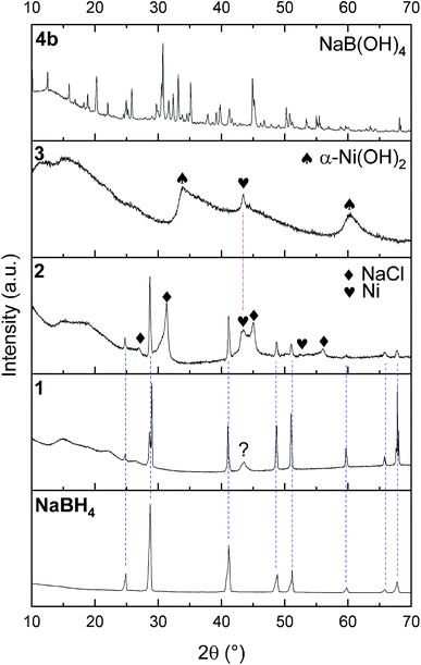
The successful preparation of 1 (i.e. the NaBH4 nanoparticles) was first verified by TEM (Fig. 1). Isolated spherical nanoparticles with a size between 5 and 40 nm were obtained (Fig. S1†). This particle size distribution is narrower than the previously reported one (2–60 nm).21,22 The molecular structure of 1 (Fig. 2) was verified by IR spectroscopy and was found to be consistent with that of bulk NaBH4. Vibration bands between 3000 and 2800 cm−1 (C–H bonds) were also seen, which are due to the stabilizing agent TOAB. The crystal structure of 1 (Fig. 3) was favorably compared to that of cubic NaBH4 (α phase; ref. code 00-009-0386). A Scherrer analysis suggested crystallites with an average size of 38 ± 2 nm and this may be associated with the larger NaBH4 nanoparticles in the sample (Fig. S2†). As for the micro-sized NaBH4 particles (i.e. bulk NaBH4),1–31 solubilizes in water (pH ≥ 7) and slowly evolves by spontaneous hydrolysis (eqn (1)). For having potential for hydrogen storage and generation, 1 has to be catalysed.4,5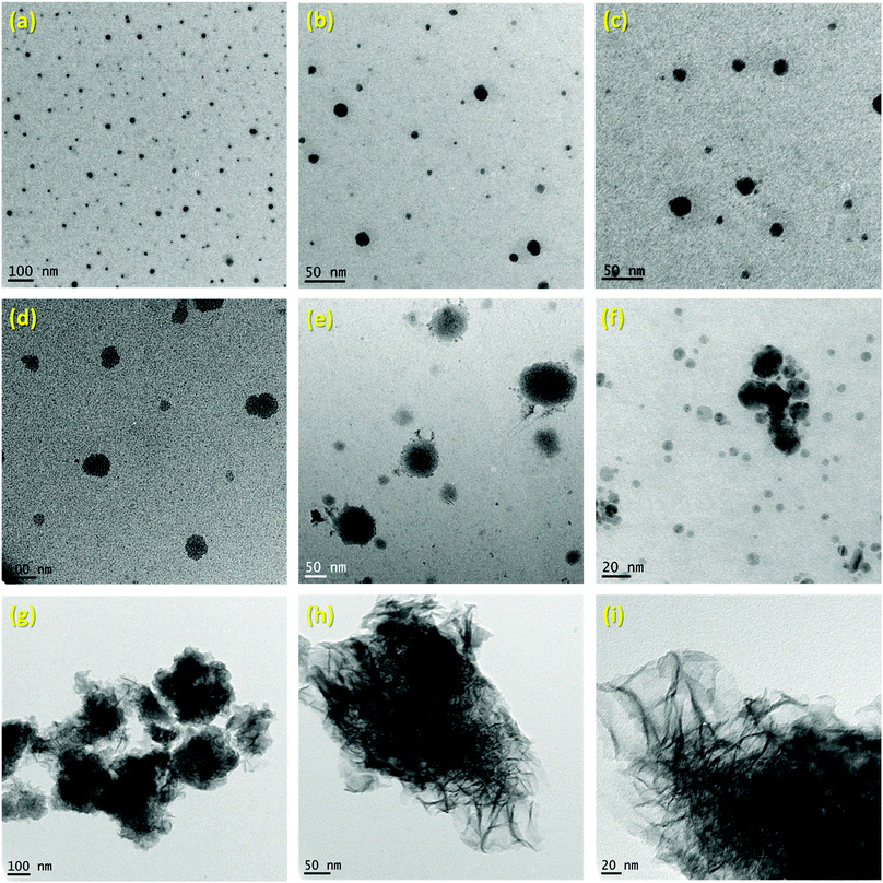 | ||
| Fig. 1 TEM images of: (a–c) 1i.e. the NaBH4 nanoparticles; (d–f) 2i.e. NaBH4@Ni; (g–i) 3i.e. the nickel-based catalyst recovered after hydrolysis. | ||
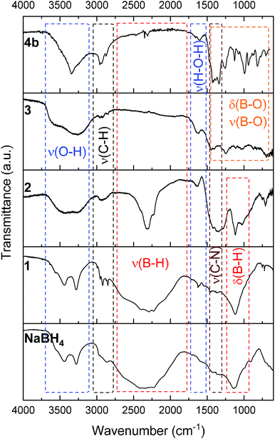 | ||
| Fig. 2 IR spectra of (from bottom to top): bulk NaBH4; 1 (the NaBH4 nanoparticles); 2 (NaBH4@Ni); 3 (the nickel-based catalyst recovered after hydrolysis); 4b (the solid-state spent fuel). | ||
1 was thus used to prepare 2 (i.e. the NaBH4-supported Ni core@shell nanocomposite) by transmetalation, which is a sacrificial method by which the surface of the nanoparticles of 1 is coated with a nickel shell via partial consumption of the surface NaBH4 molecules.21,22 This is an effective strategy to support the catalyst onto the nanosized hydrogen carrier while putting in intimate contact both components. After the transmetalation operation, 2 showed a blackish color (vs. white for 1) which is a visual indication of the reduction of Ni2+ of NiCl2 to Ni0. The successful preparation of 1 was scrutinized by TEM (Fig. 1). Spherical isolated nanoparticles (light grey) with a size between 11 and 119 nm were obtained (Fig. S3†). The size range is larger than for 1, implying coalescence of NaBH4 nanoparticles during the coating process.21 This is in agreement with our previous report, but herein the particle size distribution is narrower (11–119 nm vs. 10–200 nm).22 Darker small nanoparticles due to an element with higher electron density like Ni were observed while recovering the aforementioned spherical nanoparticles. By EDS (Fig. 4), the coexistence of both Na and Ni within each of the composite nanoparticle was confirmed; the two elements were found to be homogeneously distributed, which indicates the possible formation of a Ni shell on the surface of the NaBH4 nanoparticles. The close vicinity of Na and Ni was also confirmed by XPS. Within the 10 nm penetration depth, which allowed analyzing the surface and subsurface of the nanoparticles of 2, the elements Ni, B and Na were all detected. Even Br of TOAB and/or TBAB was detected (Fig. S4†). The binding energy (BE) of Ni 2p3/2 is 852.4 eV (Fig. 5); this is typical of the metal Ni0 (confirming the reduction of Ni2+ by NaBH4).23 For B 1s, two peaks were observed, at 188 and 192.5 eV (Fig. 6). The former BE is much likely due to NaBH4,24 although nickel boride Ni2B is at the same binding energy.23 With respect to the BE of 192.5 eV, it is generally attributed to B–O bonds,25 but the formation of borates under our experimental conditions is unlikely (which is besides supported by the absence of oxidized nickel). Such a BE is also typical of B bound to Cl.24 The formation of B–Cl bonds most likely occurs during the reduction of Ni2+ of NiCl2 by BH4− of NaBH4.26 With respect to Na 1s (Fig. 7), the BE of 1072.5 eV can be ascribed to Na+ in NaBH4 and NaCl.24 Indeed, the XRD pattern of 2 (Fig. 3) shows diffraction peaks ascribed to NaBH4 (ref. code 00-009-0386), NaCl (ref. pattern 04-002-1178) and cubic Ni (ref. code 03-065-0380). The fingerprint of NaBH4 was confirmed by IR spectroscopy (Fig. 2), discarding the presence of borate species. It is worth mentioning that the stretching bands of the B–H bonds are narrower than that for bulk NaBH4, which may be due to a lower degree of freedom because of the metallic shell (assimilated to a confinement effect).27 Consistent with our previous achievement,21,22 all of these results (i.e. small Ni0 nanoparticles coating larger NaBH4 spherical nanoparticles and close vicinity of Ni and Na as confirmed by both EDS and XPS) are in good agreement with the formation of 2, a nanocomposite mainly consisting of a core of NaBH4 and a shell of Ni0.
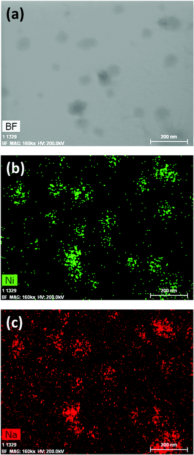 | ||
| Fig. 4 EDS results of 2 (NaBH4@Ni): (a) bright field (BF) image; (b) mapping of nickel (Ni); (c) mapping of sodium (Na). | ||
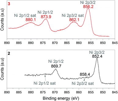 | ||
| Fig. 5 XPS analyses of 2 (NaBH4@Ni) and 3 (the nickel-based catalyst recovered after hydrolysis): focus on the Ni 2p spectra. | ||
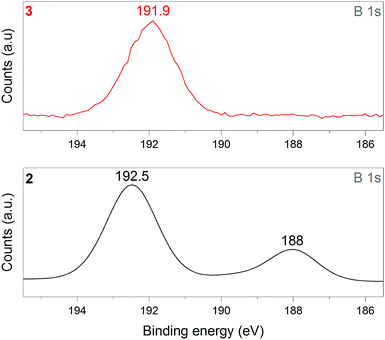 | ||
| Fig. 6 XPS analyses of 2 (NaBH4@Ni) and 3 (the nickel-based catalyst recovered after hydrolysis): focus on the B 1s spectra. | ||
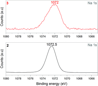 | ||
| Fig. 7 XPS analyses of 2 (NaBH4@Ni) and 3 (the nickel-based catalyst recovered after hydrolysis): focus on the Na 1s spectra. | ||
Catalytic study
The preliminary H2 evolution experiment was performed under conditions that are favorable for hydrolysis, namely at 39 °C and in the presence of an excess of water (x = 64). As the 35 mg of 2 are theoretically composed of 23.5 mg of NaBH4 and 5.3 mg of nickel (theoretical molar ratio NaBH4/Ni of 6.9), a total conversion of NaBH4 (eqn (1)) should have produced 59.7 mL of H2 (with Vm = 24 L mol−1). The H2 evolution curve (Fig. 8) however shows a final volume of 42 mL, which is equivalent to 70.4% of the theoretical target of 59.7 mL. The measured volume of 42 mL suggests therefore a molar ratio NaBH4/Ni of 4.9 (i.e. 70.4% of the aforementioned theoretical ratio of 6.9). In other words, 2 moles of NaBH4 per mole of Ni are “missing” for H2 generation. The value of 2 moles of NaBH4 is in fact typical of the amount of NaBH4 required to reduce a metal(II) cation like Ni2+.23,28 Under our conditions, the synthesis of 2 implies thus the consumption of two equivalents of the starting NaBH4 for reducing one equivalent of NiCl2. Accordingly one may assume that the content of unreacted NaBH4 in 2 is effectively 47.3 wt% (i.e. 70.4% of 23.5 mg NaBH4 in the weighed 35 mg of 2). In view of this assumption, the weight of unreacted NaBH4 in our 35 mg of 2 would be 16.55 mg and a total conversion would result in the evolution of 42 mL (Fig. 8). The spent fuel 4a (which is in the liquid state) was analyzed by 11B NMR to ensure the total conversion of NaBH4 (Fig. 9). The spectrum features two signals with positive chemical shifts belonging to B(OH)3 under alkaline conditions (δ = 11.9 ppm) and B(OH)4− (δ = 4.2 ppm).29 These results confirm a total conversion of NaBH4 under our hydrolytic conditions. It is thus reasonable to conclude that each Ni2+ cation is reduced by two equivalents of NaBH4 for forming 2, and that 2 is composed of 47.3 wt% NaBH4. As mentioned above, this implies, for 2, a NaBH4![[thin space (1/6-em)]](https://www.rsc.org/images/entities/char_2009.gif) :
:![[thin space (1/6-em)]](https://www.rsc.org/images/entities/char_2009.gif) Ni0 stoichiometry of 4.9
Ni0 stoichiometry of 4.9![[thin space (1/6-em)]](https://www.rsc.org/images/entities/char_2009.gif) :
:![[thin space (1/6-em)]](https://www.rsc.org/images/entities/char_2009.gif) 1 (which takes into account the amount of NaBH4 consumed for reducing N2+ to Ni0).
1 (which takes into account the amount of NaBH4 consumed for reducing N2+ to Ni0).
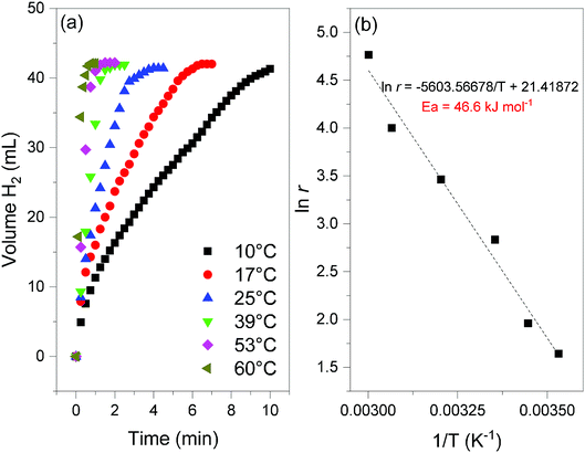 | ||
Fig. 8 (a) Hydrogen evolution curves of 2 (NaBH4@Ni; 35 mg) obtained at different temperatures (from 10 to 60 °C) and for x = 64 (cf.eqn (2)). (b) Determination of the apparent activation energy (Ea, in kJ mol−1) from the slope of the linear evolution of the natural logarithm of the H2 generation rate (ln![[thin space (1/6-em)]](https://www.rsc.org/images/entities/char_2009.gif) r, with r in mL min−1) as a function of the inverse of the temperature (T in Kelvin). r, with r in mL min−1) as a function of the inverse of the temperature (T in Kelvin). | ||
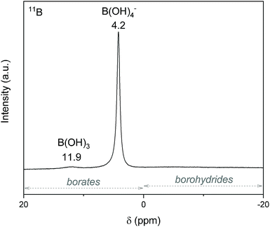 | ||
| Fig. 9 11B NMR spectrum of 4a (the liquid-state spent fuel). The typical chemical shift ranges for borohydrides and borates are indicated by the arrows. | ||
At 39 °C and in an excess of water (x = 64), the hydrogen generation rate, calculated from the linear part of the curve, was determined to be 31.9 mL min−1. Expressed per gram of Ni, the rate is 6.1 L min−1 g−1. This is one of the highest rates ever reported for a nickel catalyst and it is comparable to the rates reported for the best unsupported cobalt-based catalysts (5–10 L min−1 g−1).5,30,31 The temperature was varied to tune the hydrogen generation rate (Fig. 8). It was found to be as high as 22.5 L min−1 g−1 at 60 °C, and as low as 1 L min−1 g−1 at 10 °C. In addition, rates of about 1.4, 3.3 and 10.6 L min−1 g−1 were measured at 17, 25 and 53 °C respectively. These rates confirm the good to very good performance of 2, over a wide range of temperature (10–60 °C).5,30,31 With the help of the Arrhenius equation, the apparent activation energy was determined to be 46.6 kJ mol−1 (Fig. 8). This is consistent with the energies reported so far for the catalytic hydrolysis of NaBH4.32 The results discussed above show that 2 is an attractive and performing nanocomposite to be used as a catalyzed hydrogen carrier in a demonstrator designed using solid-state NaBH4. The total conversion of the borohydride and high hydrogen generation rates can be achieved.
Post-hydrolysis analyses
After hydrolysis, the nickel-based solid 3 was separated from the liquid-state spent fuel 4a by centrifugation. 3 was washed several times and dried before analysis by TEM, EDS, XPS, IR and XRD. 3 consisted of big agglomerates (hundreds of nm) where the initial nanoparticles cannot be distinguished anymore (Fig. 1). The images show a difference of brightness suggesting a light-grey matrix of lighter elements (i.e. B and Na) surrounding the metal-based agglomerates. This behavior is typical of nickel- and cobalt-based catalysts upon hydrolysis.33,34 Although initially they were in the form of nanoparticles, they generally form agglomerates of metal oxide/hydroxide surrounded by a matrix mainly containing hydrated sodium (poly-)borates (NanBmOpHp·qH2O).25 By EDS (Fig. 10), the presence of nickel and sodium in 3 was confirmed. According to the XPS results (Fig. 5–7),24 these elements are oxidized (NiII and Na+). The Ni 2p BEs (i.e. 2p3/2, 2p3/2 sat, 2p1/2 and 2p1/2 sat) all suggest Ni(OH)2 (Fig. 5), which is in agreement with the post-hydrolysis oxidation of nickel (Ni0 → NiII) as reported elsewhere.35 The Na 1s BE is typical of Na+ (Fig. 7), compensating the negative charge of Cl− and/or that of borates. With respect to Cl−, it (Cl 2p3/2 BE of 198.3 eV) was detected by XPS (Fig. S5†). The borates were revealed by XPS (Fig. 6, with a B 1s BE of 191.9 eV)25 as well as by IR analysis (Fig. 2) which shows vibration bands ascribed to B–O and O–H bonds in the hydrated sodium polyborates (NanBmOpHp·qH2O).363 was found to be mainly amorphous (Fig. 3),33,34 with a few peaks belonging to the α phase of Ni(OH)2,37,38 in agreement with the XPS analysis. It can thus be concluded that 3 consists of agglomerated Ni(OH)2 particles surrounded by a matrix made of NanBmOpHp·qH2O and NaCl.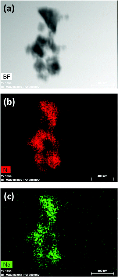 | ||
| Fig. 10 EDS results of 3 (the nickel-based catalyst recovered after hydrolysis): (a) bright field (BF) image; (b) mapping of nickel (Ni); (c) mapping of sodium (Na). | ||
As discussed above, the liquid-state spent fuel 4a (Fig. 9) is an alkaline aqueous solution of B(OH)4− in equilibrium with a small fraction of its acidic form B(OH)3 (pKa = 9.3). The solution was also subjected to chemical analysis by ICP-OES to check for the presence of Ni2+. No trace of this cation was found (within the detection limit of the spectrometer). In other words, leaching of Ni of 2 did not take place under our hydrolysis conditions. Water of 4a was then extracted. A white solid, 4b, was obtained (i.e. the solid-state spent fuel) and analyzed. The IR spectrum (Fig. 2) was found to be typical of NaB(OH)4.36 The vibration bands due to C–H stretching between 3000 and 2800 cm−1 may be ascribed to TOAB and/or TBAB. The XRD pattern is comparable to the reference pattern of NaB(OH)4 (ref. code. 04-011-2875). This is in good agreement with the occurrence of the reaction depicted by eqn (1).
Hydrogen storage capacities
Additional H2 evolution experiments were performed with 2 to optimize the gravimetric hydrogen storage capacity of the couple NaBH4–H2O. To this end, the amount of H2O (characterized by x in eqn (2)) was decreased from x = 64 to x = 4 while the temperature was 39 °C (Fig. 11).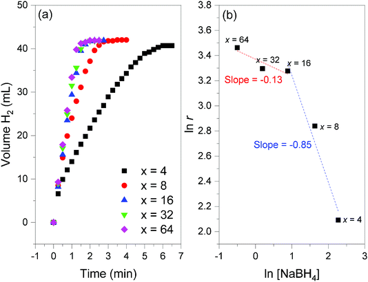 | ||
Fig. 11 (a) Hydrogen evolution curves of 2 (NaBH4@Ni; 35 mg) obtained at 39 °C and for different x values (from 4 to 64; cf.eqn (2)). (b) Determination of the reaction order versus the concentration of NaBH4 ([NaBH4]) from the slope of the linear evolution of natural logarithm of [NaBH4] as a function of the natural logarithm of the H2 generation rates (ln![[thin space (1/6-em)]](https://www.rsc.org/images/entities/char_2009.gif) r); the slopes are indicated. r); the slopes are indicated. | ||
Prior to the discussion about the storage capacities, two preliminary observations have to be reported. First, the final volume of H2 detected was 42 mL, and this suggested a total conversion of NaBH4 amounting to 47.3 wt% 2. Second, the kinetics of H2 release was impacted by the water amount, especially for x < 16. The lower the value x, the longer the reaction. For example, the experiment was completed after 6 min for x = 4 whereas it took ∼2 min for x ≥ 16. The differences are much less important for x = 16, 32 and 64. Hydrogen generation rates of 8.1, 17.1, 26.5, 27 and 31.9 mL min−1 (or 1.6, 3.3, 5.1, 5.2 and 6.1 L min−1 g−1) were determined for x = 4, 8, 16, 32 and 64, respectively. By plotting the natural logarithm of the rate as a function of the logarithm of the concentration of NaBH4 (Fig. 11), the reaction order versus the concentration of NaBH4 was found to be −0.13 for x ≥ 16 ([BH4−] ≤ 2.4 mol L−1) and −0.85 for x ≤ 16 ([BH4−] ≥ 2.4 mol L−1). A negative reaction order is generally explained by hardly desorbing borate by-products,39 because of water deficit and the relatively low solubility of NaB(OH)4 (3.5 mol L−1). This is in line with our results for x ≤ 16. The near-zero order found for x ≥ 16 is quite typical of diluted NaBH4 solutions.32,40 The catalytic behavior of Ni0 of 2 is thus comparable to that of previously reported metal-based catalysts.5,30,31,39–41
The best gravimetric hydrogen storage capacity was expected for the reaction involving the lower amount of H2O (x = 4). By taking into account the weight of 2, that of H2O, and the content of NaBH4 in 2, an effective gravimetric hydrogen storage capacity of 4.4 wt% can be proposed. This is a high effective capacity.14 As a comparison one may cite a commercial device based on an alkaline solution of 20 wt% NaBH4: the theoretical gravimetric hydrogen storage capacity of the fuel is 4.2 wt%, whereas the weight of the catalyst is not taken into consideration in the calculation of the capacity.11 It is worth mentioning that, under our conditions, when x = 8, the effective gravimetric hydrogen storage capacity is about 2.8 wt%, which is quite attractive when the hydrogen generation rate (3.3 L min−1 g−1) is also regarded.
Prospects
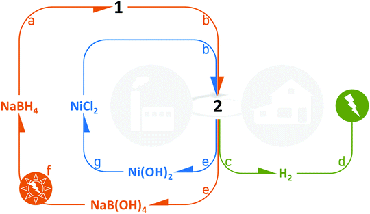
We have shown that 2 is easily prepared and is an attractive all-in-one solution to be used as a solid-state catalyzed hydrogen-rich nanocomposite based on both NaBH4 and the cheap metal Ni0. Indeed, NaBH4 of 2 is totally converted into H2 and NaB(OH)4 over the temperature range 10–60 °C, and the hydrogen generation rates are high. From a technological point of view, the sample offers several other advantages (Fig. 12). In 2, the hydrogen carrier and the catalyst are combined, which avoids the user handling two separate chemicals. 2 can be easily loaded into a cartridge/reactor and the hydrolysis reaction can be triggered simply by adding the required amount of water.14After the reaction, the cartridge/reactor is filled with Ni(OH)2 and borates. An additional amount of water can be added to the mixture to allow separation by centrifugation. The former solid can be industrially/chemically valorized under acidic conditions to reform NiCl2.42 The aqueous solution can be handled for isolating NaB(OH)4 and recycling it following one of the processes under investigation.43,44 The viability of the regeneration of NaBH4 from NaB(OH)4 strongly depends on how the energy cost can be lowered; this clearly implies the use of renewable energy sources.452 is thus a candidate for relevantly closing the H2 cycle with NaBH4 and control the life cycle of the Ni-based catalytic material.
Irrespective of the hydrogen generation rates, quite high effective gravimetric hydrogen storage capacities (material-based) can be achieved. Under our conditions, the best performance was found to be 4.4 wt%, which may be seen as being outstanding.46 Installed on a device for which the weight of 2 would represent 50% of the weight of the storage system (taken as a whole, i.e. including all of the components), one may expect a neat (i.e. system-based) gravimetric hydrogen storage capacity of 2.2 wt%. This should open implementation prospects for portable and mobile fuel cell-powered devices like laptop computers, power generators, and electric bicycles.
Conclusions
The potential of a hybrid structure where a Ni catalyst is supported on the surface of NaBH4 nanoparticles, i.e. core@shell nanocomposite, was investigated for hydrogen generation through hydrolysis of NaBH4. By hydrolysis at temperatures varying from 10 to 60 °C, H2 was successfully generated from this core–shell structure but with some notable features. In particular, high hydrogen generation rates were recorded in the presence of an excess of water (such as H2O/NaBH4 = 64). For example, the rates were found to be 6.1 and 22.5 L min−1 g−1 at 39 and 60 °C, respectively, and these values are among the fastest hydrogen generation rates reported so far. Upon the completion of the H2 generation, the hydrolysis by-product was identified as NaB(OH)4 and the nickel-based catalyst evolved into agglomerates of Ni(OH)2. In other words, recycling the end-product to regenerate the starting materials, NaBH4 and NiCl2, would be possible through conventional chemical routes. Besides the attractive catalytic performance of the proposed core–shell approach for hydrogen generation, another advantage of our NaBH4@Ni0 nanocomposite is the possibility to get high effective gravimetric hydrogen storage capacities by decreasing the amount of water necessary to the hydrolysis reaction. We optimized the conditions to achieve an effective capacity of 4.4 wt%, which is a very attractive value that may open technological application prospects for portable and mobile fuel cell-powered devices, for example.Conflicts of interest
There are no conflicts to declare.Acknowledgements
UBD and DA thank the Agence Nationale de la Recherche (ANR), Paris, France (project MobiDiC; ANR-16-CE05-0009) for funding. QL and KFAZ gratefully acknowledge financial support by the UNSW Internal Research Grant program as well as the Office of Naval Research (Award No: ONRG – NICOP – N62909-16-1-2155). QL and KFAZ appreciate the use of instruments in the Mark Wainwright Analytical Centre at UNSW as well as equipment funded by the Australian Research Council (ARC).Notes and references
- H. I. Schlesinger, H. C. Brown, A. E. Finholt, J. R. Gilbreath, H. R. Hoekstra and E. K. Hyde, J. Am. Chem. Soc., 1953, 75, 215 CrossRef CAS.
- Q. L. Zhu and Q. Xu, Energy Environ. Sci., 2015, 8, 478 RSC; M. Yadav and Q. Xu, Energy Environ. Sci., 2012, 5, 9698 RSC.
- J. Zhang, T. S. Fisher, J. P. Gore, D. Hazra and P. V. Ramachandran, Int. J. Hydrogen Energy, 2006, 31, 2292 CrossRef CAS.
- H. J. Kim, K. J. Shin, H. J. Kim, M. K. Han, H. Kim, Y. G. Shul and K. T. Jung, Int. J. Hydrogen Energy, 2010, 35, 12239 CrossRef CAS.
- P. Brack, S. E. Dann and K. G. U. Wijayantha, Energy Sci. Eng., 2015, 3, 174 CrossRef CAS.
- E. Y. Marrero-Alfonso, J. R. Gray, T. A. Davis and M. A. Matthews, Int. J. Hydrogen Energy, 2007, 32, 4723 CrossRef CAS.
- E. Petit, P. Miele and U. B. Demirci, ChemSusChem, 2016, 9, 1777 CrossRef CAS PubMed.
- J. H. Kim, K. H. Choi and Y. S. Choi, Int. J. Hydrogen Energy, 2010, 35, 4015 CrossRef CAS.
- J. Kim and T. Kim, Appl. Energy, 2015, 160, 945 CrossRef CAS.
- H. Kim, T. H. Oh and S. Kwon, Int. J. Hydrogen Energy, 2016, 41, 1018 CrossRef CAS.
- N. Lapeña-Rey, J. A. Blanco, E. Ferreyra, J. L. Lemus, S. Pereira and E. Serrot, Int. J. Hydrogen Energy, 2017, 42, 6926 CrossRef.
- E. Okumus, F. G. B. San, O. Okur, B. E. Turk, E. Cengelci, M. Kilic, C. Karadag, M. Cavdar, A. Turkmen and M. S. Yazici, Int. J. Hydrogen Energy, 2017, 42, 2691 CrossRef CAS.
- F. C. Wang and W. H. Fang, Int. J. Hydrogen Energy, 2017, 42, 10376 CrossRef CAS.
- U. B. Demirci, Energy Technol., 2018, 6, 470 CrossRef CAS.
- G. M. Arzac, M. Paladini, V. Godinho, A. M. Beltrán, M. C. Jiménez de Haro and A. Fernández, Sci. Rep., 2018, 8, 9755 CrossRef CAS PubMed.
- E. S. Jung, H. Kim, S. Kwon and T. H. Oh, Int. J. Green Energy, 2018, 15, 385 CrossRef CAS.
- U. B. Demirci, Int. J. Hydrogen Energy, 2015, 40, 2673 CrossRef CAS.
- O. V. Netskina, O. V. Komova and V. I. Simagina, Catal. Ind., 2018, 10, 166 CrossRef.
- P. P. Prosini and P. Gislon, J. Power Sources, 2006, 161, 290 CrossRef CAS.
- Project in progress at the University of Montpellier, Institut Européen des Membranes, IEM, not yet published Search PubMed.
- M. L. Christian and K. F. Aguey-Zinsou, ACS Nano, 2012, 6, 7739 CrossRef CAS PubMed.
- M. Christian and K. F. Aguey-Zinsou, Chem. Commun., 2013, 49, 6794 RSC.
- J. Legrand, S. Gota, M. J. Guittet and C. Petit, Langmuir, 2002, 18, 4131 CrossRef CAS.
- A. V. Naumkin, A. Kraut-Vass, S. W. Gaarenstroom, and C. J. Powell, NIST Standard Reference Database 20, Version 4.1, web version, http:/srdata.nist.gov/xps/, 2012 Search PubMed.
- U. B. Demirci and P. Miele, Phys. Chem. Chem. Phys., 2014, 16, 6872 RSC.
- S. B. Kalidindi, J. Joseph and B. R. Jagirdar, Energy Environ. Sci., 2009, 2, 1274 RSC.
- A. V. Iogansen, Spectrochim. Acta, Part A, 1999, 55, 1585 CrossRef.
- G. N. Glavee, K. J. Klabunde, C. M. Sorensen and G. C. Hadjipanayis, Langmuir, 1994, 10, 4726 CrossRef CAS.
- K. Ishihara, A. Nagasawa, K. Umemoto, H. Ito and K. Saito, Inorg. Chem., 1994, 33, 3811 CrossRef CAS.
- U. B. Demirci, O. Akdim, J. Andrieux, J. Hannauer, R. Chamoun and P. Miele, Fuel Cells, 2010, 3, 335 CrossRef.
- S. S. Muir and X. Yao, Int. J. Hydrogen Energy, 2011, 36, 5983 CrossRef CAS.
- R. Retnamma, A. Q. Novais and C. M. Rangel, Int. J. Hydrogen Energy, 2011, 36, 9772 CrossRef CAS.
- J. Andrieux, D. Swierczynski, L. Laversenne, A. Garron, S. Bennici, C. Goutaudier, P. Miele, A. Auroux and B. Bonnetot, Int. J. Hydrogen Energy, 2009, 34, 938 CrossRef CAS.
- Z. Wu, X. Mao, Q. Zi, R. Zhang, T. Dou and A. C. K. Yip, J. Power Sources, 2014, 268, 596 CrossRef CAS.
- J. H. Kim, K. T. Kim, Y. M. Kang, H. S. Kim, M. S. Song, Y. J. Lee, P. S. Lee and J. Y. Lee, J. Alloys Compd., 2004, 379, 222 CrossRef CAS.
- L. Jun, X. Shuping and G. Shiyang, Spectrochim. Acta, Part A, 1995, 51, 519 CrossRef.
- H. Y. Wu, Y. L. Xie and Z. A. Hu, Int. J. Electrochem. Sci., 2013, 8, 1839 CAS.
- D. S. Hall, D. J. Lockwood, C. A. Bock and B. R. MacDougall, Proc. R. Soc. A, 2014, 471, 20140792 CrossRef PubMed.
- F. Baydaroglu, E. Özdemir and A. Hasimoglu, Int. J. Hydrogen Energy, 2014, 39, 1516 CrossRef CAS.
- N. Patel, R. Fernandes and A. Miotello, J. Power Sources, 2009, 188, 411 CrossRef CAS.
- U. B. Demirci and P. Miele, C. R. Chim., 2014, 17, 707 CrossRef CAS.
- B. Beverskog and I. Puigdomenech, Corros. Sci., 1997, 39, 969 CrossRef CAS.
- M. Rivarolo, O. Improta, L. Magistri, M. Panizza and A. Barbucci, Int. J. Hydrogen Energy, 2018, 43, 1606 CrossRef CAS.
- H. Zhong, L. Z. Ouyang, J. S. Ye, J. W. Liu, H. Wang, X. D. Yao and M. Zhu, Energy Storage Materials, 2017, 7, 222 CrossRef.
- M. Monteverde and L. Magistri, Int. J. Hydrogen Energy, 2012, 37, 5452 CrossRef CAS.
- J. Ren, N. M. Musyoka, H. W. Langmi, M. Mathe and S. Liao, Int. J. Hydrogen Energy, 2017, 42, 289 CrossRef CAS.
Footnote |
| † Electronic supplementary information (ESI) available: Fig. S1–S4. See DOI: 10.1039/c9na00037b |
| This journal is © The Royal Society of Chemistry 2019 |

