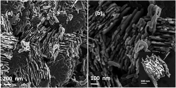
 Open Access Article
Substrate-independent and catalyst-free synthesis of magnesium nanowires†
Haritha
Vijayakumar Sheela
,
Vimal
Madhusudhanan
and
Gopi
Krishnan
 *
*
Amrita Centre for Nanosciences and Molecular Medicine, Amrita Vishwa Vidyapeetham, Kochi, Kerala 682041, India. E-mail: gopi.k.krish@gmail.com
First published on 15th February 2019
Abstract
We report a catalyst free and substrate independent synthesis of magnesium nanowires using a simple thermal evaporation method. The produced Mg nanowires have a size of 8–60 nm with a crystalline MgO shell of ∼2–5 nm thickness. The synthesized nanowires grow along the [001] direction and horizontal to the substrate. Moreover, from ex situ TEM investigation the various sequential stages involved in the nanowire formation process were identified. The experimental outcome indicates the sequential stages including (i) formation of Mg nanoparticles, (ii) coarsening of Mg nanoparticles to microparticles via deposition diffusion aggregation (DDA) and the orientation attachment (OA) process, and (iii) nucleation and growth of Mg nanowires. In depth analysis confirms two types of nanowires, straight and serpentine-like, where the latter dominates as the holding duration/temperature of the synthesis increases. The straight nanowires are formed by the direct attachment of nanodroplets from the core to the surface and serpentine-like wires are formed on the surface of a microparticle which is in a quasi-melted state. Moreover, nanowires were produced by confining the Mg vapour to the substrate using a curved quartz bottle, thereby controlling the supersaturation in the absence of any inert/reactive gas during the synthesis. Our synthesis method is cost effective and can be applied to other low melting point elements for producing various nanostructures. Finally based on the experimental results a possible growth mechanism is proposed.
Introduction
Magnesium (Mg), an environmentally friendly, low cost, light and abundant element in the Earth's crust, is found to have a wide variety of applications in areas like the automotive, biomedical, aerospace industries, hydrogen storage and batteries.1–9 Nanostructures of Mg are gaining a lot of interest in the field of energy storage10 and as nanoplasmonic materials.11Synthesis of one-dimensional structures of Mg, including columnar arrays of rods, blades and sea-urchin like structures, was reported by adopting various PVD techniques like glancing angle deposition, oblique angle deposition, vapour transport,10,12,13etc. Nevertheless, synthesis of Mg nanowires is least explored to date. It is particularly very interesting for hydrogen storage applications as reported both theoretically and experimentally. Moreover a quantum chemical study on ∼1 nm thick MgH2 nanowires has shown a reduction in desorption energy to half of that of bulk MgH2, a lower desorption temperature of 287 K and an identical theoretical hydrogen storage capacity of 7.6 wt%.14,15 Interestingly, experimental investigations on thinner Mg nanowires of size between 30 to 50 nm show a lower desorption energy and an improved absorption kinetics compared to thicker nanowires of size varying from 150 to 170 nm, indicating the necessity for size reduction.16 However, size reduction of Mg/MgH2 nanowires is considered as a great challenge and not much research has been conducted yet. This is clearly owing to Mg's high affinity towards oxygen, which can lead to hollow MgO or MgO nanowire formation. On the other hand, the direct synthesis of one dimensional MgH2 nanostructures is possible; however, to create a possible interaction of Mg (g) and H2 (g) generally a higher H2 pressure (∼30 bar) is required. Moreover such synthesis based on high pressure CVD has resulted in the formation of MgH2 fibres that show sizes in the range of several hundreds of nanometres.17–19 Furthermore, in the synthesis of Mg nanoparticles it was reported that homogeneous nucleation of Mg is difficult and the presence of trace impurities is necessary for the nucleation of Mg.20,21 All these drawbacks make it difficult to synthesize the nanostructures of Mg. Although there have been reports on the synthesis of thicker Mg nanowires by PVD methods,22,23 there is still a lack of complete understanding on the formation, growth, control over the nanowire dimensions, effect of the substrate and void formation during oxidation.
Mostly nanowires rely on growth mechanisms that are assisted by a solid or a liquid catalyst, generally termed vapour solid solid (VSS) and vapour liquid solid (VLS) growth mechanisms.24 Though more focus has been placed on the nucleation and growth of nanowires on a catalyst, there are plenty of reports on other growth mechanisms which do not involve a catalyst like the vapour-solid growth mechanism,25,26 where the one-dimensional crystallization will be assisted by the surface energy anisotropy of the crystal.27 Although there are numerous reports on the synthesis of metal oxide nanowires by the vapour solid mechanism, there are only a few reports on the synthesis of metal nanowires by VS growth.28,29 Metal nanowires, having a great demand in areas like sensors, interconnects, magnetic recording, catalysis, etc, mostly depend on synthesis techniques like template assisted electrodeposition, glancing angle deposition (GLAD) and chemical vapour deposition (CVD) for the growth.30–32 There are some limitations or shortcomings associated with these techniques, such as the removal of templates, shadowing and contamination due to the use of organometallic precursors. The use of a direct metal powder as the source can prevent some of the issues; however, confining metal vapor in the case of Mg (i.e., low melting point elements) on to the substrate is a key limitation that has to be overcome. Moreover, introducing the carrier gas during evaporation of the metal powder is useful in controlling the supersaturation but producing nanostructures of Mg that are sensitive to oxygen will be challenging. Furthermore, this will require an ultra-high vacuum based setup in order to prevent the effect of impurities on nanowire formation, which will increase the production cost. So, in this report we demonstrate a simple and cost-effective thermal evaporation technique to produce Mg nanowires via the vapour solid mechanism through a catalyst free and substrate independent approach.33 Also, we demonstrate a simple strategy by using a curved quartz bottle to confine Mg vapour to control the supersaturation and deposition on to various substrates.
Results and discussion
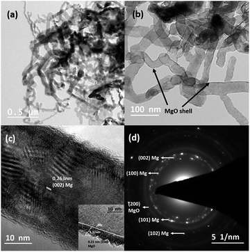
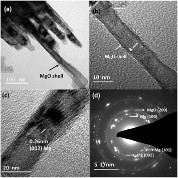
Fig. 1(a) and (b) depict the bright-field TEM images of Mg nanowires that were produced at an evaporation temperature of 700 °C and deposited directly on a carbon coated copper TEM grid. The deposited nanowires show a serpentine like appearance as commonly observed for low melting elements, e.g. Zn and Cd.28,34,35Fig. 1(c) shows the HRTEM image of a Mg nanowire with a resolved interplanar distance (d) of 0.263 nm, which matches with the (002) plane of Mg. Moreover, a crystalline MgO shell of ∼3–4 nm thickness is observed in all the nanowires as shown in Fig. 1(b) and the inset of Fig. 1(c) presents the reconstruction of MgO, where the {220} plane of MgO transforms into stable {200} planes in order to reduce its surface energy under electron beam.36 The (200) plane of MgO has the lowest surface energy compared to MgO (220). The formation of the MgO shell occurs during its exposure to the outside atmosphere and not during the synthesis as mentioned for gas phase synthesized Mg nanoparticles.36 However the crystalline oxide shell shows similarity to previously reported Mg nanoparticles.20,21,36 The formation of this self-limiting MgO shell follows the oxidation mechanism that is well explained by the widely accepted Cabrera–Mott theory for low temperature oxidation.36–38 The selected area electron diffraction (SAED) pattern shown in Fig. 1(d) shows the characteristic reflection of HCP Mg and a faint MgO reflection that are indexed to Mg (JCPDS file 044-1288) and MgO (JCPDS file 019-0771). Mg nanowires produced at 700 °C show a size range from 25 to 60 nm with an average diameter of 43 nm and a length of 1–2 micrometres. It is observed that nanowires align in-plane to the substrate and grow in the [001] direction, as commonly observed for the HCP crystal structure due to its anisotropy in the C axis.35 Moreover; nanowires do not show any void formation in the process of oxide shell formation.Now in order to observe the effect of temperature and to reduce the nanowire diameter and size distribution, we have reduced the evaporation temperature to 600 °C. In contrast to that observed in Fig. 1 this sample shows a uniform distribution of short and straight Mg nanowires with an average diameter of 27 nm and a length less than 1 μm as shown in Fig. 2(a). Moreover, it can be observed that the nanowires appear to be free from void and hollow formation even when the size of the nanowires has been reduced to less than 10 nm. Fig. 2(b) shows a high magnification TEM image of a void-free Mg nanowire of ∼8 nm diameter. This observation is in contrast to Mg nanoparticles that are prone to void and hollow formation as the size of the particle decreases <10 nm.39 Furthermore, the HRTEM image shown in Fig. 2(c) confirms the direction of growth along [001] as the (002) basal plane of Mg was resolved. This also confirms that the growth directions for both straight and serpentine like nanowires produced at 700 °C and 600 °C are similar. Moreover, the SAED pattern shown in Fig. 2(d) also confirms the smaller size distribution of Mg nanowires from the diffused nature of the pattern.
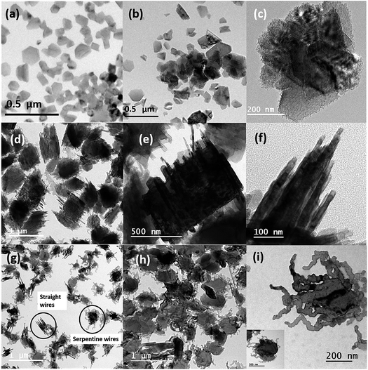
From Fig. 1 and 2 it can be observed that there is a considerable effect of temperature on the synthesis of Mg nanowires; more importantly, at 600 °C straight and short nanowires with reduced diameters were observed. In order to understand this difference in the formation of nanowires, we have performed ex situ TEM analysis at the different sequential stages involved in the synthesis of nanowires. When the holding time was reduced to 1 minute at 600 °C, instead of Mg nanowires, Mg nanoparticles with sizes varying from 30 to 100 nm and with an average size of 61.88 nm were observed. These Mg nanoparticles were also found to show a crystalline oxide shell of thickness <∼3 nm, similar to previously reported Mg nanoparticles.36Fig. 3(a) shows the bright-field TEM image of Mg nanoparticles that were produced at 600 °C for 1 minute. It also shows that in addition to nanoparticle formation there appears to be a coarsening of the nanoparticles to reduce the overall surface energy. Moreover, due to the high mobility of Mg atoms a rapid coarsening of nanoparticles can easily occur at higher temperatures (∼100–150 °C). Fig. 3(b) and (c) shows the bright-field TEM images of Mg nanoparticle during coarsening/growth at other regions of the grid. It can be observed that these smaller particles are finally transforming into bigger Mg structures as shown in Fig. 3(c). This difference in some regions of the grid is due to the temperature difference that exists during the holding duration on the substrate but most importantly it shows the sequential transformation of Mg nanoparticles into microparticles before nanowire formation. Moreover, the coarsening of nanoparticles clearly indicates that the oxide shell on these particles is developing only when the samples are exposed to the outside atmosphere. In contrast, if the oxidation of Mg was initiated inside the furnace then the coarsening would have stopped due to the presence of the oxide shell and microparticles would not have formed. Subsequently from the images it can be understood that once Mg vapour deposits on to the substrate, the atoms nucleate on the substrate to form clusters which further grow into small nanoparticles and finally transform into a stable hexagonal prismatic shape as commonly observed for Mg nanoparticles. The transformation of spherical nanoparticles into hexagonal prismatic shaped particles is governed by the HCP crystal structure of Mg as well as due to surface energy minimization.40
This overall process can be understood by the deposition–diffusion–aggregation (DDA) model for smaller particles, orientation attachment (OA) for medium sized particles and grain rotation coalescence (GRC) for bigger structures. Smaller particles, once formed on the substrates or after being deposited directly on to the substrate from vapour, will try to aggregate through the DDA process41 to form bigger nanoparticles. Moreover, smaller nanoparticles (≤5 nm) can easily diffuse on the substrate to grow bigger as reported earlier for Mg at room temperature.42 But in our case as the substrate temperature is higher a high mobility of the particles can be expected. Also, the growth of lower melting point elements (like Mg and Zn) on the substrates is determined by the ratio of the substrate temperature to the melting temperature, denoted as the homologous temperature (Th). At an evaporation temperature of 600 °C and a holding duration of 1 min, the homologous temperature is calculated to be Th = 373 K/923 K = 0.40, which indicates that the growth of Mg will come under the zone II in accordance with the structural zone model and which in turn indicates a high atomic mobility for the Mg atoms.13,43 Now once the particles grow bigger, the diffusion of the particles on the substrate slows down and the particles further grow by orientation attachment (OA) as shown in Fig. S1 (ESI†), which clearly shows the orientation attachment of two particles, and the HRTEM image exhibits a mirror-like twin boundary that forms during particle attachment in the (101) plane. This occurs by the coordinated rotation of particles to attach in the particular orientation to eliminate the particle interface and reduce the overall surface/interface energy of the particles. Our observation shows a certain similarity to previously reported coarsening of Mg nanoparticles produced by the gas phase method at room temperature;42 however, in our case the temperature is above room temperature and formation of nanoparticles occurs on the substrate.
To further investigate the effect of holding time on the growth of particles into Mg nanowires, the holding duration is increased from 1 minute to 2 minutes 30 seconds at the same evaporation temperature of 600 °C. Once the holding duration is increased to 2 minutes 30 seconds, the faceted Mg nanoparticles are completely absent and rather large Mg particles are observed as shown in Fig. S2 (ESI†). Moreover, these Mg particles appear to be quasi melted or in the liquid state, which could be due to a combined effect of (i) the increase in substrate temperature, as a result of increased holding duration, and (ii) the heat generated due to the reduction in surface energy/area during the coarsening process. Moreover, from Fig. S2 (ESI†) it can be noticed that there is also nucleation of nanoparticles on the core/surface of the microparticles, indicating high degree of supersaturation on the substrate for the nucleation of the nanoparticles. Furthermore, when the holding time is increased to 5 minutes, growth of Mg nanowires is observed as shown in Fig. 3(d)–(f).
From Fig. 3 it can be seen that the nanowires are formed from the bulk of the microparticles and the complete transformation of microparticles into nanowires is not yet finished; moreover, a closer inspection of the TEM images confirms that the wires have a diameter range from 8 to 20 nm. Although the formation of straight Mg nanowires starts to appear at 5 minutes of deposition the serpentine like nanowires are still absent. Now in order to observe this transition, we again increased the holding duration to 15 minutes and as shown in Fig. 3(g) serpentine like Mg nanowires were observed in addition to straight wires and they grew from the surface of the particles unlike straight nanowires that grew from the core of the particles. Furthermore, as the evaporation temperature was increased to 700 °C, only the growth of serpentine like Mg nanowires was observed and it was only dominant on the surface of the microparticles as seen from Fig. 3(h) and (i). Subsequently, the complete transformation of microparticles into nanowires at 700 °C is reflected in Fig. 1. Finally, these observations indicate that the formation processes and growth of these two types of nanowires are completely different.
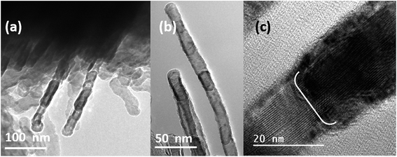
In order to understand this difference in growth, we have evaporated Mg at 600 °C and deposited it for 3.5 minutes. From Fig. 4 it can be seen that the straight nanowires are growing by the attachment of nanoparticles. A closer look at the high magnification HRTEM images shown in Fig. 4(b) and (c) confirms that this is not similar to the orientation-attachment of particles that is commonly observed for the growth of nanowires. Moreover, the nanoparticles observed here are in the liquid state, so called nanodroplets, and the growth of the nanowires takes place by the attachment of the droplets on top of each other. Furthermore, from Fig. 4 it can be observed that these individual nanoparticles which are aligning to form nanowires have an oxide shell. This provides an indirect evidence that the droplets are attaching to form nanowires and the droplets that are not completely merged into wires develops an oxide shell during outside exposure. Other evidence that we could find in support of the above observation is that once the substrate is moved 1 cm towards the hot zone of the furnace from the current position the particles appeared to be completely hollow as sublimation of the nanoparticles occurs.38 Besides this, during the formation of nanowires these particles are trying to align in the direction of nanowire growth as shown in Fig. 4(b), which also indicates that these particles are nanodroplets. Moreover, the nanodroplets after attachment grow into bigger droplets and try to get aligned in the one-dimensional form to merge in the process of nanowire formation. However, in the case of serpentine-like nanowires, the growth tends to occur from the surface and in comparison the length also appears to be longer. A closer inspection of the TEM images shown in Fig. 3(h) and (i) reveals that the whole microparticles are transforming into nanowires and the particle seems to be completely transformed into the liquid state. Simultaneously the liquid Mg acts as a source for the growth of Mg nanowires. Furthermore, with an increase in temperature the mobility of Mg is also simultaneously increased, and the nanowires appear to be serpentine-like and grow uniformly throughout the sample.
Now in order to eliminate the effect of the substrate on the nanowire formation and to show that this mechanism is of substrate independent nature, we have deposited the nanowires on stainless steel foil at an evaporation temperature of 700 °C. Fig. 5 shows the SEM images of both types of nanowires, similar to our previous observation on a carbon coated copper grid. Moreover, this observation is contrary to previously reported papers16,22,23 which state that nanowires could be only deposited on a stainless steel mesh and not even on stainless steel foil. Also, it was mentioned that the deposition on any other substrates was difficult and unsuccessful.23 However in our case in addition to stainless steel foil we were able to produce nanowires on a quartz substrate and Pd coated grids, indicating that the growth of the nanowires is independent of the substrate and the presence of rough surfaces/nanopits is not a prerequisite for the growth of Mg nanowires. More importantly we were able to deposit Mg on various substrates by employing a curved quartz bottle with a neck region that allowed us to confine and control the vapor. Interestingly, on a occasions we also see the growth of particles and a few nanowires on the copper edge of the grid, where the rough surface of the copper acts as a nucleation centre for the growth.
From Fig. 1–5 as illustrated earlier, the formation and growth of nanowires appear to be dominated by homogeneous nucleation and totally dependent on the high degree of supersaturation conditions. However, the effect of heterogeneous nucleation and impurities on the nucleation of nanowires cannot be completely neglected. Moreover, Mg has a nucleation issue and homogeneous nucleation is difficult; therefore, mostly heterogeneous nucleation and impurities like oxygen, carbon and hydrogen that react to form Mg-X species can favour the nucleation process.20,21 In order to understand the stability of Mg nanowires and to show the effect of impurities/vacuum conditions on the growth and formation of the Mg nanowires, we have reduced the pumping duration and thus increased the pressure of the setup. More importantly the idea is to increase the partial pressure of impurities inside the setup without the introduction of carrier gases. Fig. 6 shows the TEM images of nanowires of size between ∼8 and 15 nm grown at 700 °C and 10−3 mbar. It can be observed that growth of nanowires starts from the surface of the particles and the length of the produced nanowires is also longer. This observation is different from the earlier discussed nanowires shown in Fig. 1–5 which were produced at 10−6 mbar. Moreover, a more uniform nanowire growth on the surface of the particles can be seen; however, in addition the presence of voids can be observed as well, which is due to (i) the increase in oxygen partial pressure under these conditions or (ii) the size reduction of the produced nanowires, where voids develop due to the oxidation assisted Kirkendall effect during oxide shell formation. Interestingly the nanowires formed at 10−6 mbar in a similar size regime do not show any void formation, indicating the role of oxygen partial pressure at 10−3 mbar in the formation of voids. Nevertheless, under the same conditions the number of nanowires formed and growth have increased which can be attributed to the presence of impurities that favour the nucleation of Mg at the surface. More preferably it can be argued that it is the oxygen that favours the formation of Mg nanoparticles due to its high reactivity with Mg, which allows the formation of stable Mg–O dimers during the nucleation process on the surface of the microparticles.20 Other impurities unless supplied continuously cannot favour the complete nucleation of particles as mentioned in our earlier articles.20,21 In spite of this difference in observation a more detailed study using a controlled introduction of oxygen is necessary in the future for a quantitative understanding of the same.
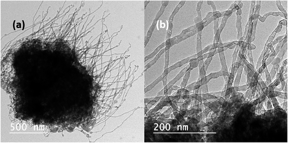 | ||
| Fig. 6 (a) Bright-field TEM image of Mg nanowires formed at a pressure of 10−3 mbar and (b) high magnification bright-field TEM image of the nanowire representing the void formation. | ||
In addition, the other difference to observe is that the microparticle does not seem to be in the melted state as observed at 600 °C and 700 °C at 10−6 mbar. This can be understood by the fact that under low vacuum conditions (10−3 mbar) the melting of the microparticles does not occur, which also restricts the formation and growth of the nanowires to the surface alone and a complete transformation of microparticles into nanowires is not possible. Since the partial pressure of oxygen should be higher under low vacuum conditions, the nuclei density on the surface of the particle increases naturally, which in turn reduces the diameter of the nanowires formed on the surface. Subsequently also, from Fig. S3 (ESI†) it can be observed that the growth of nanowires is by the attachment of smaller nanoparticles at the surface.
Furthermore, a complete understanding on the formation and the growth of Mg nanowires can only lead to a complete control over the nanowire dimensions. In our case, the absence of a catalyst tip eliminates the conventional growth mechanisms that are assisted by a liquid or a solid catalyst, like the VLS and VSS growth mechanisms. In addition, the lack of continuous supply of oxygen, absence of screw dislocations and nature of the metal source also eliminate other growth mechanisms e.g. oxide assisted, screw dislocation assisted, solid diffusion, etc.44,45 Our experimental investigations clearly eliminate the substrate dependency along with other growth mechanisms and lead us to a substrate independent vapour solid growth mechanism for the growth of Mg nanowires. From Fig. 1–5 the formation process of Mg nanowires can be divided into the following sequence: (i) sublimation and deposition of Mg on to the substrate, (ii) nanoparticle formation on the substrate, (iii) coarsening of nanoparticles, (iv) nucleation of nanoparticles on microparticles, and (v) growth of nanowires.
In general, the growth of nanowires strongly depends on the anisotropy properties of crystal facets and the crystal structure. More importantly it is the supersaturation condition that allows the formation of nanowires. A control over the supersaturation ratio or degree of supersaturation can be achieved by altering the synthesis conditions like evaporation temperature, heating rate, substrate temperature, position, etc.46 Generally as the supersaturation ratio exceeds unity (S > 1), the crystal growth will be far away from the thermal equilibrium condition and will favour the anisotropic growth of nanostructures e.g. nanorods, nanowires, nanobelts, etc. And a higher degree of supersaturation ratio (S ≫ 1) will favour the formation of nanoparticles. In the case of thermal evaporation in tube furnaces the degree of supersaturation can be controlled depending on the temperature gradient between the evaporation (isothermal) and deposition zones (supersaturation), vapour pressure and vapour concentration on the substrates.46–48 Moreover, in our experimental setup, an increment in the holding duration/an increase in temperature can alter the temperature gradient between the source and the deposition zone, as we use rapid thermal heating and a single zone furnace for evaporation and deposition. Also, in addition to the rapid heating rate, a simultaneous faster cooling rate will allow quenching the formed structures rather than normal cooling of the furnace. A more detailed study on the rapid heating/cooling rates will be reported elsewhere. Now with this background information if we try to understand the formation process of nanowires, at 600 °C for 1 min, the Mg vapour deposits on to the substrate and the aggregation of atoms lead to the formation of Mg nanoparticles due to their higher mobility, which eventually undergo the coarsening process to reduce the surface energy by DDA and OA. Moreover, it has to be taken into account that the Mg nanoparticles synthesized by the gas phase method via thermal evaporation showed particle coarsening on the TEM grid even at room temperature as the deposition rate was simultaneously increased.42 So, in our case at higher temperature we expect higher mobility of Mg atoms and therefore a faster coarsening of particles. Moreover, low melting point elements (Mg and Zn) have a higher diffusion rate as reported in earlier articles.13,43 Later, once the particles transform into microparticles within 1 min duration, simultaneously the formation of Mg nanoparticles starts to appear on the surface of the microparticles. This transformation is due to the increased holding duration that eventually changes the temperature gradient between the source and the substrate and achieves a higher supersaturation condition that favours nanoparticle formation. Moreover, the above step is completed within a holding duration of 2 minutes 30 s as shown in Fig. S3 (ESI†).
Further, in order to confirm this behaviour, we have placed the substrate in a much cooler region (∼150 °C), where the temperature difference between the source and the substrate is large and correspondingly a higher degree of supersaturation (S ≫ 1) can be achieved. Fig. S4 (ESI†) shows that microparticles are almost transformed into nanoparticles and no traces of nanowires are observed. However, during the continuous process, since the temperature of the substrate is still rising (∼200–250 °C) after microparticle formation, due to the increase in holding duration to 5 min, the degree of supersaturation decreases S > 1 near the substrate, which favours the formation of nanowires/anisotropic growth. Importantly the rise in temperature under this condition transforms the formed nanoparticles (nuclei) into liquid state/Mg nanodroplets, due to the reduction in melting point as the size of the particles is decreased.38,39 This condition drives the already formed nanodroplets from the microparticles to attach themselves in a sequence and merge to form nanowires. The driving force for the merging/coalescence of nanodroplets is to reduce the interfacial energy as shown in Fig. 4. Subsequently once the holding duration increases to 15 minutes, the surface of microparticles will completely transform into the melted state and the formation of serpentine like nanowires begins from the surface as shown in Fig. 3(g). Also, as the surface of the particles transforms into the liquid state, the localized area of higher surface energy with imperfection, humps and bumps will act as a nucleation centre for Mg nanowire growth. Moreover, the interface between the Mg melt and the vapour becomes one of the most energetically favoured places for the nucleation. And finally, once the temperature is increased to 700 °C for the same holding duration of 15 min, it leads only to the formation of serpentine-like nanowires. This difference points out that as the temperature of the substrate increases (300–350 °C) the probability of formation of serpentine like nanowire increases and it dominates completely at higher evaporation temperatures provided the supersaturation condition for nanowire formation is satisfied. More details about the experimental conditions, which result in the various growth stages of magnesium nanowires, are summarised in Table 1.
| Evaporation temperature | Holding duration | Substrate temperature | Observation |
|---|---|---|---|
| 600 °C | 1 minute | ∼100–150 °C | Mg nanoparticles |
| 600 °C | 2 minutes 30 seconds | ∼150–200 °C | Quasi melted Mg microparticles |
| 600 °C | 5 minutes | ∼200–250 °C | Straight Mg nanowires |
| 600 °C | 15 minutes | ∼250–300 °C | Both straight and serpentine like Mg nanowires |
| 700 °C | 15 minutes | ∼300–350 °C | Serpentine like Mg nanowires |
Moreover, we have strategically employed a curved quartz bottle inside a tube furnace to control and confine the vapour on to the substrate, as shown in Fig. 7(a). Importantly it allows the deposition of Mg on to the substrate. In addition, at higher substrate temperatures the growth of nanowires is very rapid, and they grow from the microparticles that have transformed into a completely melted/liquid state due to the rise in temperature. A schematic representation of the formation and growth of both straight as well as serpentine Mg nanowires is shown in Fig. 7(b). The formation and growth of nanowires from liquid droplets, similar to our observation, has been reported for metal oxide nanowires synthesised through the Ostwald ripening/coalescence of nanoliquid droplets at temperatures below the melting point of the material.49,50 However these reports are for metal oxide nanowires and it happens directly on the substrate by either merging of the nanodroplets or growth from the bigger droplets. Moreover, the choice of substrate has an effect on the wettability of the droplets, thereby changing the morphology of the final structure. In contrast, we report the formation of Mg nanowires from microparticles without any effect of the substrate.
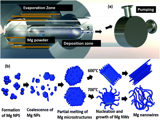 | ||
| Fig. 7 The schematic representation of (a) the experimental setup and (b) the process of Mg nanowire formation. | ||
Conclusion
Mg nanowires of size between 8 and 60 nm with a protective crystalline MgO shell of thickness less than 5 nm were successfully synthesised by a vacuum based thermal evaporation method. The temperature and holding duration play a significant role in the synthesis of straight and serpentine-like Mg nanowires that are morphologically different. Moreover, higher temperature leads to the formation of serpentine-like nanowires and low temperature leads to the formation of straight wires. The formation/growth process is also different in both kinds of wires; straight wires were found to show a nanodroplet attachment growth, whereas the serpentine-like nanowires directly transform from completely melted Mg microparticles. Note that only temperature has a crucial role in the formation and growth of Mg nanowires, and a higher partial pressure of oxygen has also favoured heterogeneous nucleation and has resulted in the formation of longer and thinner Mg nanowires that are prone to oxidation and void formation compared to wires grown at low partial pressure. Furthermore, with the use of an inner quartz bottle we were able to strategically control and confine the vapour deposition on the substrate. Our experimental investigations propose a substrate-independent vapor solid mechanism for the growth of nanowires. Finally the produced Mg nanowires can have profound applications in hydrogen storage, Mg/air batteries, plasmonics, etc.Experimental procedure
Synthesis of nanowires
Fig. 7(b) demonstrates the schematic diagram of the vacuum based thermal evaporation setup. Commercially available Mg powder of purity >99% was purchased from Alfa Aesar. 50 mg of Mg powder is packed in a molybdenum boat and is placed inside a quartz bottle with an outer body diameter of 50 mm and a curvature of size 20 mm. The quartz bottle containing the Mg powder is placed inside a tubular RTP furnace and the whole setup is evacuated to a base pressure of 10−5 to 10−6 mbar. As it is similar to the thermal evaporation method, we do not do any flushing with inert gases before the evacuation process. Then the Mg powder was evaporated at different evaporation temperatures like 600 °C and 700 °C with a constant heating rate of 300 °C min−1 at different holding durations ranging from 1 min to 15 min. Mg vapour was collected in the cooler regions and both stainless steel foil as well as carbon coated TEM grids were used as the substrates, which are at a distance of 15 cm from the Mg powder. After the deposition, a blank run will be performed for the whole setup at a temperature of 800 °C for cleaning the setup.TEM analysis
TEM analysis of Mg nanowires was performed using an FEI Technai-F20 operating at 200 kV. Nanowires deposited on the carbon coated copper grid were directly used for TEM analysis.Conflicts of interest
There are no conflicts to declare.Acknowledgements
We would like to acknowledge the support of this work from the Department of Science and Technology (DST) India through DST INSPIRE FACULTY award DST/INSPIRE/04/2013/000470. We would also like to thank Dr R. Pandian, Mrs Arya Raju and Miss Haritha T. J. for their contribution in SEM and TEM analyses.References
- C. Blawert, N. Hort and K. U. Kainer, Trans. Indian Inst. Met., 2004, 57, 397–408 CAS.
- M. F. Ryan, Ann. Clin. Biochem., 1991, 28, 19–26 Search PubMed.
- M. Villeta, B. De Agustina, J. M. S. De Pipaón and E. M. Rubio, Int. J. Adv. Des. Manuf. Technol., 2012, 60, 1237–1246 CrossRef.
- W. Grochala and P. P. Edwards, Chem. Rev., 2004, 104, 1283–1315 CAS.
- C. Lu, J. Zou, X. Shi and X. Zeng, Int. J. Hydrogen Energy, 2016, 42, 1–9 Search PubMed.
- X. Chen, J. Zou, X. Zeng and W. Ding, Int. J. Hydrogen Energy, 2016, 41, 14795–14806 CrossRef CAS.
- J. Mao, J. Zou, C. Lu, X. Zeng and W. Ding, J. Power Sources, 2017, 366, 131–142 CrossRef CAS.
- D. Aurbach, Z. Lu, A. Schechter, Y. Gofer, H. Gizbar, R. Turgeman, Y. Cohen, M. Moshkovich and E. Levi, Nature, 2000, 407, 724–727 CrossRef CAS PubMed.
- B. Peng, J. Liang, Z. Tao and J. Chen, J. Mater. Chem., 2009, 19, 2877–2883 RSC.
- W. Li, C. Li, C. Zhou and H. Ma, Angew. Chem., Int. Ed., 2006, 45, 6009–6012 CrossRef CAS PubMed.
- J. Biggins, S. Yazdi and E. Ringe, Nano Lett., 2018, 3752–3758 CrossRef CAS PubMed.
- S. U. Bayca, M. F. Cansizoglu, A. S. Biris and F. Watanabe, Int. J. Hydrogen Energy, 2011, 36, 5998–6004 CrossRef CAS.
- F. Tang, T. Parker, H. Li, G. Wang and T. Lu, J. Nanosci. Nanotechnol., 2007, 7, 3239–3244 CrossRef CAS PubMed.
- X. Wu and J. Yang, Phys. Chem. Chem. Phys., 2016, 18, 19412–19419 RSC.
- B. Peng, L. Li, W. Ji, F. Cheng and J. Chen, J. Alloys Compd., 2009, 484, 308–313 CrossRef CAS.
- W. Li, C. Li, H. Ma and J. Chen, J. Am. Chem. Soc., 2007, 129, 6710–6711 CrossRef CAS PubMed.
- C. Zhu, H. Hayashi, I. Saita and T. Akiyama, Int. J. Hydrogen Energy, 2009, 34, 7283–7290 CrossRef CAS.
- C. Zhu, N. Sakaguchi, S. Hosokai, S. Watanabe and T. Akiyama, Int. J. Hydrogen Energy, 2011, 36, 3600–3605 CrossRef CAS.
- C. Zhu, S. Hosokai and T. Akiyama, Int. J. Hydrogen Energy, 2012, 37, 8379–8387 CrossRef CAS.
- G. Krishnan, S. de Graaf, G. H. ten Brink, P. O. Å. Persson, B. J. Kooi and G. Palasantzas, Nanoscale, 2017, 9, 8149–8156 RSC.
- G. Krishnan, S. de Graaf, G. H. ten Brink, M. A. Verheijen and B. J. Kooi, Nanoscale, 2017, 10, 1297–1307 RSC.
- H. Wang, X. Song, L. You and B. Zhang, J. Cryst. Growth, 2015, 432, 78–82 CrossRef CAS.
- H. Wang, X. Song, L. You and B. Zhang, Scr. Mater., 2015, 108, 68–71 CrossRef CAS.
- Z. Zhang, Y. Wang, H. Li, W. Yuan, X. Zhang, C. Sun and Z. Zhang, ACS Nano, 2016, 10, 763–769 CrossRef CAS PubMed.
- K. Chen, Z. Huang, J. Huang, M. Fang, Y. Liu, H. Ji and L. Yin, Ceram. Int., 2013, 39, 1957–1962 CrossRef CAS.
- S. Sakrani, N. Jamaludin, R. Muhammad, Y. Wahab, A. K. Ismail, S. Suhaimi and Y. H. Mohammed, AIP Conf. Proc., 2016, 1733, 1–6 CrossRef.
- M. Kast, P. Schroeder, Y. J. Hyun, P. Pongratz and H. Brückl, Nano Lett., 2007, 7, 2540–2544 CrossRef CAS PubMed.
- Y. J. Chen, B. Chi, H. Z. Zhang, H. Chen and Y. Chen, Mater. Lett., 2007, 61, 144–147 CrossRef CAS.
- Y. Hsu and S. Lu, J. Phys. Chem. B, 2005, 109, 4398–4403 CrossRef CAS PubMed.
- M. Tian, J. Wang, J. Kurtz, T. E. Mallouk and M. H. W. Chan, Nano Lett., 2003, 3, 919–923 CrossRef CAS PubMed.
- M. S. Ã, H. Minamitake, R. Kita, K. Hamachi and H. Hara, Jpn. J. Appl. Phys., 2013, 52, 1–6 Search PubMed.
- J. Benson, S. Boukhalfa, A. Magasinski, A. Kvit and G. Yushin, ACS Nano, 2012, 6, 118–125 CrossRef CAS PubMed.
- C. Ye, G. Meng, Y. Wang, Z. Jiang and L. Zhang, J. Phys. Chem. B, 2002, 106, 10338–10341 CrossRef CAS.
- S. Kar, T. Ghoshal and S. Chaudhuri, Chem. Phys. Lett., 2006, 419, 174–178 CrossRef CAS.
- Y. Yan, P. Liu, M. J. Romero and M. M. Al-Jassim, J. Appl. Phys., 2003, 93, 4807–4809 CrossRef CAS.
- B. J. Kooi, G. Palasantzas and J. T. M. De Hosson, Appl. Phys. Lett., 2006, 89, 1–4 CrossRef.
- N. Cabrera and N. F. Mott, Rep. Prog. Phys., 1949, 12, 163–184 CAS.
- Z. Zhang, X. Fu, M. Mao, Q. Yu, S. X. Mao, J. Li and Z. Zhang, Nano Res., 2016, 9, 2796–2802 CAS.
- G. Krishnan, B. J. Kooi, G. Palasantzas, Y. Pivak and B. Dam, J. Appl. Phys., 2010, 107, 053504 Search PubMed.
- Q. Yang, J. Sha, L. Wang, J. Wang and D. Yang, Mater. Sci. Eng., C, 2006, 26, 1097–1101 CrossRef CAS.
- P. Jensen, A. L. Barabási, H. Larralde, S. Havlin and H. E. Stanley, Phys. Rev. B, 1994, 50, 15316 CrossRef CAS.
- F. Venturi, M. Calizzi, S. Bals, T. Perkisas and L. Pasquini, Mater. Res. Express, 2015, 2, 15007 Search PubMed.
- Y. He and Y. Zhao, Cryst. Growth Des., 2010, 10, 440–448 CAS.
- M. J. Bierman, Y. K. A. Lau, A. V Kirt, A. L. Schmitt, M. Bierman, Y. K. A. Lau, A. V Kvit, A. L. Schmitt and S. Jin, Am. Assoc. Adv. Sci., 2008, 320, 1060–1063 CAS.
- R. López, E. Vigueras-Santiago, P. E. Acuña-Avila, S. Hernández-López, G. López-Téllez, E. A. Zaragoza-Contreras, C. A. Hernández-Escobar, W. Antünez and N. Torres-Gómez, Bull. Mater. Sci., 2015, 38, 1777–1781 CrossRef.
- C. Ye, X. Fang, Y. Hao, X. Teng and L. Zhang, J. Phys. Chem., 2005, 109, 19758–19765 CrossRef CAS PubMed.
- P. Mohanty, T. Kang, B. Kim and J. Park, J. Phys. Chem. B, 2006, 110, 791–795 CrossRef CAS PubMed.
- R.-Q. Zhang, Y. Lifshitz and S.-T. Lee, Adv. Mater., 2003, 15, 635–640 CAS.
- M. H. Kim, B. Lee, S. Lee, C. Larson, J. M. Baik, C. T. Yavuz, S. Seifert, S. Vajda, R. E. Winans, M. Moskovits, G. D. Stucky and A. M. Wodtke, Nano Lett., 2009, 9, 4138–4146 CrossRef CAS PubMed.
- E. Strelcov, A. V Davydov, U. Lanke, C. Watts and A. Kolmakov, ACS Nano, 2011, 5, 3373–3384 CrossRef CAS PubMed.
Footnote |
| † Electronic supplementary information (ESI) available: Experimental details including TEM images of Mg nanowires, nanoparticle formation, and the intermediate stage in nanowire formation. See DOI: 10.1039/c9na00072k |
| This journal is © The Royal Society of Chemistry 2019 |

