 Open Access Article
Development of near-infrared sensitized core–shell–shell upconverting nanoparticles as pH-responsive probes†
Manoj Kumar
Mahata
 and
Kang Taek
Lee
 *
*
Department of Chemistry, School of Physics and Chemistry, Gwangju Institute of Science and Technology (GIST), Gwangju 61005, Korea. E-mail: ktlee@gist.ac.kr
First published on 30th April 2019
Abstract
Recently, the functionalization of nanoparticles, either within themselves or on the outer surface and its application in medicine, turned out to be the ultimate goal of nanotechnology. By providing these nanoparticles with chemical functional groups, one can force the nanoparticles to target the markers of the particular diseases or to measure the quantity and distribution of various intracellular species. In this paper, we report our development of a pH-responsive nanocomposite based on lanthanide-doped upconverting nanoparticles (UCNPs). Through multiphoton absorption and energy migration between spatially separated Nd3+, Yb3+, and Tm3+ in a three-layered NaYF4 host coated with FITC (fluorescein-5-isothiocyanate), this nanocomposite can measure the pH with high sensitivity. The fundamental acidity measurement is based on the pH-dependent equilibrium of the bright and dark states of FITC. The tremendous advantages of this system, regarding the pH measurement, come from the fact that the versatility of UCNP-imaging can fully be exploited. This includes the fact that (a) the optical wavelengths for the sensitization (980 nm and/or 808 nm) and the emission bands (UV, visible) are well separated, (b) the spectral overlap between FITC (absorption) and Tm3+ (emission) is substantially high, (c) there is no background signal due to the near-infrared laser, and (d) the signals are consistent regardless of the fluctuations by monitoring the ratio of blue band with respect to the unaffected self-reference (red and near-infrared bands). Moreover, the double shell structure is obviously superior to the core–shell structure in that it enhances the spectral separation between the sensitizer and the emitter in the upconversion process, inhibiting any unnecessary contamination in the spectra. Finally, it is noteworthy that Yb3+ plays crucial roles as a sensitizer at 980 nm excitation and a bridge above which 808 nm excitation migrates from Nd3+ to Tm3+via the Yb3+ excited state.
Introduction
Upconversion nanoparticles featuring the capability of converting near-infrared (NIR) into visible light have attracted significant interest from researchers due to their emerging applications in nanotechnology in the past decade.1–4 The exceptional optical properties of the lanthanide (Ln)-activated upconversion nanoparticles are generated from the forbidden f–f electronic transitions in the 4f shell of Ln3+ ions, though the 4f shell is shielded by the electrons from the 5s and 5p shells. This fundamental perspective regulates the splitting of the energy multiplets, narrow spectral lines and long lifetimes, thereby providing highly photostable and diverse emission bands spanning from the ultraviolet (UV) to NIR window. The upconverting nanoparticles are suitable for a wide range of biological applications, owing to their excellent advantageous features in biosystems, such as low photobleaching, the absence of biomolecular autofluorescence, deep penetration depth, etc.5,6 Easy separation of the emission bands are accessible from the excitation light due to large anti-Stokes shift of the upconversion nanoparticles. Their low cytotoxicity and non-exhibition of photoblinking are some additional features that lead them to be beneficial in biological cell imaging and small animal imaging.7,8 However, the nanoparticles face some challenges, such as biocompatibility with proper labelling for specific site targeting, low quantum yields, etc. In this context, a couple of approaches have been tried to resolve the problems in advancing facile applications.9,10 For example, nanoparticles, structuring the core with multiple shells, have been developed to obtain high-intensity emission, along with selective emission bands by controlling the crystal phase, size, dopant concentration or excitation energy.11–13 The biological environments of the nanoparticles are designed to be stable by conjugating with some polymers including polyethyleneimine (PEI), polyacrylic acid (PAA), polyethylene glycol (PEG), etc.10,14The development of optical sensors for the detection of temperature, pH and metal ions in the biological specimens has received great attention.15 Measurement of temperature and pH at the intracellular level is equally important as measuring the spatial distribution of ions and their concentrations to understand the physiological responses.16 The cellular compartments have specific pH-values that are supposed to provide various conditions for each metabolic route. In particular, pH has a crucial role in regulating the cellular processes, and aberrant deviation of intracellular pH may indicate abnormal cellular biological processes and cellular dysfunction. Apart from this, in order to understand membrane dynamics, vesicle trafficking, phagocytosis and endocytosis, the determination of pH is an essential priority.17 Thus, in biomedical research, it is necessary to develop accurate and reliable sensors in order to monitor the pH in living cells. So far, several fluorescent detection systems have been reported for pH-measurement.18–20 For instance, pH-sensitive organic molecules,18 various nanomaterials including quantum dots, silica, polymers, etc., have been developed recently.19,20 Among these, although the organic dyes are highly sensitive, they have serious disadvantages, e.g., the excitation and emission bands are usually narrow in nature, which may give incorrect results due to the fluctuation of emission intensity with a lack of control over the concentration of organic molecules in the cellular compartments introduced by leaching.21 The limited excitation light at the short wavelength (UV) may also damage biological cells. On the other hand, the nanomaterials are usually based on the ratiometric detection technique but the primary demerit comes from their excitation wavelength in the high-frequency region (UV-vis), which has been proven to have various side-effects.22,23 Therefore, an essential requirement is the design of sensors for biological application, which can avoid these hindrances.
To overcome the problems encountered by organic dye molecules, a couple of models have been designed by combining upconverting nanoparticles with pH-sensitive absorbers.24–28 These nanoprobes are based on the inner filter effect, utilizing the upconversion emission as the absorption wavelength for the pH-responsive dye. The absorption wavelengths of the organic dyes have a broad spectral range and as they are pH-sensitive, their absorption also changes with pH. Luminescence resonance energy transfer (LRET) taking place at the organic/inorganic interface also varies accordingly. The first example in this category of optical pH sensors was developed on the basis of upconversion luminescence with a matrix of hydrogel, and illustrated the possibility of using the sensor in basic and acidic gases, including enzymatic biosensors by Wolfbeis and co-workers in 2009,24 followed by some other important works.25 Several other systems proposed for use in intra-cellular environments have also been developed by Schäferling and his group in recent years.25,26 However, a very limited number of works have shown efforts to rationally design the nanosensors, making it an underdeveloped field. Therefore, it is of utmost importance to explore chemically engineered molecular nanoprobes as ratiometric sensors for intra-cellular pH determination.
The 808 nm excitation wavelength can be used to avoid the over-heating effect caused by 980 nm light in the biological application, through designing the structure of the nanoparticles.29 For instance, using Nd3+ ions as the harvesting layer of the excitation photons at 808 nm may minimize the heating effect and enhance luminescence upon 808 nm excitation. Therefore, in this work, we have integrated the upconversion nanoparticles with the spatial distribution of the sensitizer and activator ions in the core–shell–shell structure with the following components: Yb3+/Tm3+ (core), Yb3+ (inner shell) and Yb3+/Nd3+ (outer shell) towards developing pH-sensitive, self-ratiometric probes in which the upconversion emission in the blue region is absorbed by the conjugated FITC molecules. The other emission bands at 643 and 802 nm have been taken as reference signals under 808 and 980 nm excitations, respectively, while the blue band at 474 nm was used as the response signal. The nanoparticles were designed to harvest the 980 nm as well as 808 nm laser excitations.
Experimental
Methods and materials
Yttrium acetate tetra-hydrate (99.9%), ytterbium acetate hydrate (99.99%), thulium acetate hydrate (99.9%), neodymium acetate hydrate (99.9%), oleic acid (technical grade, 90%), 1-octadecene (technical grade, 90%), ammonium fluoride (≥98%), sodium hydroxide (reagent grade, ≥98%), ethanol, cyclohexane, branched poly(ethylenimine) (mol. weight 25![[thin space (1/6-em)]](https://www.rsc.org/images/entities/char_2009.gif) 000), N,N-dimethylformamide (anhydrous, ≥99.8%), nitrosonium tetrafluoroborate (>98%), N-(3-dimethylaminopropyl)-N′-ethylcarbodiimide hydrochloride (EDC, >99%), N-hydroxysulfosuccinimide sodium salt (≥98%), and fluorescein-5-isothiocyanate (FITC) were purchased from Sigma-Aldrich and used as received, without any further purification. Sodium phosphate buffer solution of pH 7–8 (100 mM) and sodium citrate with citric acid buffer (100 mM) of pH 3–6 were purchased from LPS Solution (Daejeon, South Korea) for use in the pH-dependent experiments. The water used in the synthesis was purified with a Milli-Q filtration system before use. The radius of the rotator of the centrifuge machine was 19 cm and rcf was 3399 × g (Combi 514R, Hanil Science Medical) for the centrifugation of the UCNPs' synthesis. The centrifugation force (rcf = 11
000), N,N-dimethylformamide (anhydrous, ≥99.8%), nitrosonium tetrafluoroborate (>98%), N-(3-dimethylaminopropyl)-N′-ethylcarbodiimide hydrochloride (EDC, >99%), N-hydroxysulfosuccinimide sodium salt (≥98%), and fluorescein-5-isothiocyanate (FITC) were purchased from Sigma-Aldrich and used as received, without any further purification. Sodium phosphate buffer solution of pH 7–8 (100 mM) and sodium citrate with citric acid buffer (100 mM) of pH 3–6 were purchased from LPS Solution (Daejeon, South Korea) for use in the pH-dependent experiments. The water used in the synthesis was purified with a Milli-Q filtration system before use. The radius of the rotator of the centrifuge machine was 19 cm and rcf was 3399 × g (Combi 514R, Hanil Science Medical) for the centrifugation of the UCNPs' synthesis. The centrifugation force (rcf = 11![[thin space (1/6-em)]](https://www.rsc.org/images/entities/char_2009.gif) 620 × g) was applied for the purification of FITC-conjugated PEI-UCNPs in a centrifuge (SLCF-10, SeouLin Bioscience Co. Ltd).
620 × g) was applied for the purification of FITC-conjugated PEI-UCNPs in a centrifuge (SLCF-10, SeouLin Bioscience Co. Ltd).
Synthesis of Yb3+/Tm3+-doped core nanoparticles
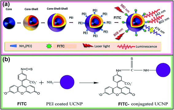
The synthesis route is schematically shown in Scheme 1a and the detailed procedure is provided below for each step.The upconverting nanoparticles were prepared by a solvothermal synthesis.30 The starting precursors were – Y(CH3COO)3·xH2O (0.795 mmol), Yb(CH3COO)3·xH2O (0.2 mmol), Tm(CH3COO)3·xH2O (0.005 mmol), oleic acid (6 mL) and 1-octadecene (15 mL), NH4F (4 mmol) and NaOH (2.5 mmol).
At first, all the lanthanide acetates were added in 5 mL of distilled water and sonicated for 15–20 minutes in a beaker. Meanwhile, a mixed solution of 15 mL of 1-octadecene and 6 mL of oleic acid was taken in a three-necked round-bottom flask. The acetate solution in water, as prepared earlier, was added dropwise to the three-necked flask. Then, the flask was heated at 150 °C for 1 hour at constant stirring to remove residual waste and oxygen, after which the solution was cooled to room temperature.
In another beaker, NH4F, NaOH and methanol (10 mL) were mixed together and sonicated for proper dissolution. The solution was added dropwise into the three-neck flask and the colour became golden-yellow at this stage. The solution was kept at constant stirring at 50 °C for 40 minutes. The reaction mixture was then heated to 100 °C under vacuum and kept for 15 minutes at constant stirring in order to remove methanol. Subsequently, the reaction solution was heated to 300 °C in an Ar environment for 1 hour. After cooling to room temperature, the core nanoparticles were precipitated by adding 15 mL of ethanol, followed by centrifugation at 4000 rpm (rcf = 3399 × g) at room temperature. The nanoparticles were further washed three times with cyclohexane/ethanol (v/v, 2![[thin space (1/6-em)]](https://www.rsc.org/images/entities/char_2009.gif) :
:![[thin space (1/6-em)]](https://www.rsc.org/images/entities/char_2009.gif) 1) and dispersed in hexane. In the second step, these core nanoparticles were coated with a layer of NaYF4:Yb3+ nanoparticles.
1) and dispersed in hexane. In the second step, these core nanoparticles were coated with a layer of NaYF4:Yb3+ nanoparticles.
Preparation of the core–shell and core–shell–shell nanostructures
The oleic acid (6 mL), 1-octadecene (15 mL) and yttrium acetate (0.02, 0.05, 0.1, 0.2, 0.3 mmol) were added to a three-necked flask and the same procedure was followed to prepare the core–shell nanoparticles as used for the preparation of the core particles.Finally, the core–shell nanoparticles were coated by using a similar procedure where the stock solutions of Y(CH3COO)3·xH2O (0.6, 0.7 and 0.8 mmol), Yb(CH3COO)3·xH2O (0.1 mmol) with a series of Nd(CH3COO)3·xH2O (0.1 mmol, 0.2 mmol and 0.3 mmol), core–shell nanoparticles in hexane (1 mmol), oleic acid (6 mL), 1-octadecene (15 mL) were mixed in a three-necked round-bottom flask. Then, the solution was heated to 150 °C with stirring for 1 hour and thereafter, cooled down to room temperature. Ammonium fluoride (2.0 mmol) and sodium hydroxide (1.25 mmol) were added in 5 mL of methanol in a beaker and after sonication, the solution was transferred to the flask. The whole solution was then stirred at 50 °C for 30 minutes, followed by heating at 100 °C for 15 minutes (in a vacuum). The solution was heated to 300 °C and kept for 1 hour under continuous stirring in an Ar-environment. After cooling down to room temperature, the precipitate was formed by the addition of 15 mL of ethanol and washed three times using 30 mL of ethanol/cyclohexane (v/v, 2![[thin space (1/6-em)]](https://www.rsc.org/images/entities/char_2009.gif) :
:![[thin space (1/6-em)]](https://www.rsc.org/images/entities/char_2009.gif) 1). Following this step, centrifugal separation was performed at 4000 rpm and the nanoparticles were re-dispersed in hexane.
1). Following this step, centrifugal separation was performed at 4000 rpm and the nanoparticles were re-dispersed in hexane.
Surface modification of the core–shell–shell nanoparticles
Branched polyethylenimine (molecular weight 25![[thin space (1/6-em)]](https://www.rsc.org/images/entities/char_2009.gif) 000) functionalized nanoparticles were synthesized by a ligand exchange reaction.30 In brief, 30 mg of the nanoparticles in 2 mL of hexane were added to the mixed solution of 25 mg of nitrosonium tetrafluoroborate (NOBF4) and 5 mL of dimethylformamide (DMF) and stirred for 10 minutes. After that, it was kept for 5–10 minutes so that the phase separation between DMF and the rest of the solution occurred. In due course, 10 mL of chloroform was added for precipitation, followed by centrifugation at 4000 rpm for 15 minutes to collect the BF4 coated nanoparticles. Then, 300 mg of PEI in 2 mL of NaOH solution was mixed with the synthesized nanoparticles in 6 mL of DMF solution and kept for 15 minutes at 1200 rpm. Finally, centrifugation of the resultant solution yielded PEI-functionalized upconversion nanoparticles, which were re-dispersed in distilled water.
000) functionalized nanoparticles were synthesized by a ligand exchange reaction.30 In brief, 30 mg of the nanoparticles in 2 mL of hexane were added to the mixed solution of 25 mg of nitrosonium tetrafluoroborate (NOBF4) and 5 mL of dimethylformamide (DMF) and stirred for 10 minutes. After that, it was kept for 5–10 minutes so that the phase separation between DMF and the rest of the solution occurred. In due course, 10 mL of chloroform was added for precipitation, followed by centrifugation at 4000 rpm for 15 minutes to collect the BF4 coated nanoparticles. Then, 300 mg of PEI in 2 mL of NaOH solution was mixed with the synthesized nanoparticles in 6 mL of DMF solution and kept for 15 minutes at 1200 rpm. Finally, centrifugation of the resultant solution yielded PEI-functionalized upconversion nanoparticles, which were re-dispersed in distilled water.
Preparation of FITC-conjugated nanoparticles
FITC was covalently conjugated to UCNP-PEI using an N-(3-dimethylaminopropyl)-N′-ethylcarbodiimide hydrochloride (EDC) and N-hydroxysulfosuccinimide sodium salt (sulfo-NHS) via an amidization reaction (Scheme 1b). In brief, 2 mL of UCNP-PEI were added to 1 mL of FITC (0.05 wt%). Then, 10 mg of EDC and 25 mg of sulfo-NHS were added to the solution and kept stirring in the dark for 24 hours. The dye-conjugated nanoparticles were centrifuged (rcf = 11![[thin space (1/6-em)]](https://www.rsc.org/images/entities/char_2009.gif) 620 × g) and washed three times with pH 9.0 buffer (carbonate–bicarbonate buffer) and distilled water. After that, the nanoparticles were dispersed in 5 mL of distilled water. The dye-conjugated nanoparticles were added to the pH buffer solutions with pH 3–8 and hexane for their luminescence measurements.
620 × g) and washed three times with pH 9.0 buffer (carbonate–bicarbonate buffer) and distilled water. After that, the nanoparticles were dispersed in 5 mL of distilled water. The dye-conjugated nanoparticles were added to the pH buffer solutions with pH 3–8 and hexane for their luminescence measurements.
Upconverting nanoparticles for pH-dependent measurements
The solutions of FITC-conjugated nanoparticles were prepared by adding 200 μL of the stock solution (10 mg mL−1) to standard pH solutions of 1800 μL each for pH 3–8. For each pH, the total solution of 2 mL was protected from light at 4 °C for the measurements.Characterization methods
The X-ray diffraction measurements were carried out with Rigaku D/Max-3C diffractometer with Cu-Kα radiation (λ = 0.154 nm) within a 2θ range of 10–80°. The morphology of the nanoparticles was characterized by a transmission electron microscope (JEOL EM-2010 TEM) with a working voltage of 200 kV. Energy dispersive X-ray (EDX) spectroscopy (operating at 200 kV) was used to perform the elemental analysis of the nanoparticles in EDX, 7200-H, Horiba, Japan, combined with a scanning electron microscope (SEM; S-4700, Hitachi Co., Japan). Upconversion luminescence measurements were recorded under 808 nm (QFLD-808-250S, QPHOTONICS) and 980 nm NIR diode laser (P161-600-980A), in a HR 2000+ Ocean Optics spectrometer with suitable optical filters. The time-resolved luminescence studies were performed on an Edinburgh FLS 920 conjugated with a pulse generator upon 808 nm laser excitation. The UV-vis absorption spectra were measured in a 10 mm optical path-length of 1.5 mL quartz cuvettes in an Ultrospec 2100 pro spectrophotometer (Amersham Biosciences) with 2 nm and 0.5 nm step size within the regions 200–900 nm and 750–850 nm, respectively, with reference to a hexane solution. The dynamic light scattering (DLS) and zeta potential measurements were performed on a Zeta-Potential & Particle size Analyzer ELSZ-2000 series, Otsuka Electronics Co. Ltd. The Fourier-transform infrared (FTIR) spectra were collected on a Nicolet iS10 FT-IR Spectrometer (Thermo Fisher Scientific), using the KBr pellet technique. A 488 nm CW laser (LBX-488-100-CIR-PP, Oxxius) was used to check the emission from the FITC-conjugated nanoparticles.Results and discussion
Characterization of the synthesized nanoparticles
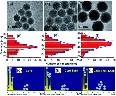
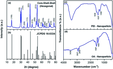
The size and shape of the core nanoparticles of β-NaYF4:20 mol%Yb3+ and 0.5 mol% Tm3+ were inspected via the transmission electron microscopy images (Fig. 1a), which showed the formation of uniform spherical nanoparticles with an average size of ∼24 nm. The core nanoparticles were consecutively coated by a shell of NaYF4:Yb3+ with a shell thickness of ∼4 nm, as determined from Fig. 1b. Subsequently, an outer shell layer containing NaYF4:Yb3+/Nd3+ was coated onto the core–shell nanoparticles and the size of the nanoparticles became ∼44 nm (Fig. 1c). The TEM images in Fig. 1d–f show that the shape of the particles did not change with adding the shell, but the size of the nanoparticles increased. The enhancement in the diameter of the core, core–shell and core–shell–shell nanoparticles was confirmed by the analysis of the statistical distribution of the nanoparticles. The energy dispersive X-ray (EDX) spectra during the layer-by-layer epitaxial growth of the nanoparticle system in Fig. 1g–i confirmed the distribution of the optically active ions in the nanoparticles. The corresponding elements were evidenced in the EDX spectra, suggesting the successful synthesis of the UCNPs. The crystal structure and phase of the synthesized particles were investigated by examining the X-ray diffraction pattern. The diffraction peaks (Fig. 2a) of the core–shell–shell nanoparticles completely matched the JCPDS no. 16-0334 of NaYF4 crystals with hexagonal phase, as shown in Fig. 2b. The analysis of the X-ray diffraction pattern additionally showed the good crystalline nature of the nanoparticles.The surface modification of the nanoparticles was monitored by Fourier transform infrared spectroscopy. The FTIR spectra (Fig. 2d) of the oleic acid coated nanoparticles showed transmittance peaks due to the presence of carboxyl (1465, 1567 cm−1) and methylene (2856, 2927 cm−1) groups, which disappeared or decreased after PEI conjugation (Fig. 2c) and thus confirmed the successful surface-modification. Three additional peaks at 1396, 1537 and 1636 cm−1 also appeared in the PEI-conjugated nanoparticles. These peaks are due to the C–N bond (1396 cm−1), free –NH2 (1537 cm−1) and N–H bond (1636 cm−1). Besides, the broad peak at 3438 cm−1 in both the samples is due to the O–H stretching vibration of H2O molecules, adsorbed on the surface of the nanoparticles.
The UV-vis absorption spectra were recorded to evaluate the optical properties of the core, core–shell and core–shell–shell nanostructures. All the spectra exhibit a broad absorption at ∼250 nm due to the band gap absorption of the host matrix. The spectra did not show the absorption bands corresponding to Tm3+ ions, which is due to its low concentration (0.5 mol%). The band at ∼795 nm (inset of Fig. S1a,† black curve) indicates the presence of Nd3+ ions in the core–shell–shell sample, while in the core and core–shell nanoparticles the band is not observed. The absorption at ∼980 nm in Fig. S1b† is obtained due to the 2F5/2 (Yb3+) ← 2F7/2 (Yb3+) transition.
Evaluation of the luminescence properties
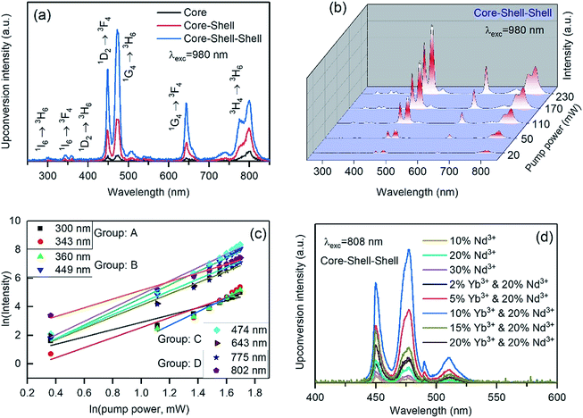
The upconversion luminescence properties were investigated by exciting the materials with 980 and 808 nm laser light. In order to determine the most efficient sample, we compared the core, core–shell and core–shell–shell nanoparticles in respect of their light emission intensity upon 980 nm excitation, as shown in Fig. 3a. The comparative spectra upon 808 nm excitation are presented in Fig. S2.† Both figures indicate that the core–shell–shell structure gives the highest luminescence emission intensity. The core–shell–shell design with a high concentration of neodymium ions (20 mol%) in the outer shell layer, significantly enhances the upconversion emission from the Tm3+-activators. The Nd3+ features an intense absorption band at ∼800 nm and facilitates the energy transfer from Nd3+ to Tm3+ through Yb3+ ions. Therefore, the rational design of the core–shell–shell strategy with a high concentration of Nd3+ ions in the outer shell effectively enhances the upconversion luminescence under laser excitation at 808 nm. The corresponding emissions from the core and core–shell nanoparticles, which contain no Nd3+ ions, show low upconversion emission intensity as compared with the core–shell–shell particles. A similar enhancement was achieved by the group of Xiaogang Liu after doping Nd3+ ions in the shell layer of core–shell nanostructures.31The typical upconversion luminescence spectra of Tm3+ ions upon 980 nm laser excitation (200 mW pump power) are shown in Fig. 3a. The spectra show that Tm3+ produces emissions in the UV, visible and NIR regions. The nature of the upconversion emission bands was investigated by studying pump-power dependent upconversion luminescence properties (Fig. 3b). The slope of the logarithmic plots of pump power vs. emission intensity yields the number of photons involved in the upconversion processes. The bands that appear in the spectrum can be broadly categorized into four groups on the basis of their level of origin as presented in Table S1† and Fig. 3c. The levels of origin of those groups are A (300, 343 nm), B (360, 449 nm), C (474, 643 nm) and D (785, 802 nm) are 1I6, 1D2, 1G4 and 3H4, which require at least 5, 4, 3 and 2 pump photons, respectively, to be populated upon 980 nm excitation (Fig. S3a†).
The non-resonant energy transfer, involved in the Yb3+ → Tm3+ occurs with the support of multi-phonon relaxations and according to the Miyakawa–Dexter theory,32 the efficiency is higher for the host matrices with high phonon energy. The multiphonon relaxation transition occurs consistent with the energy gap law, which can be written as follows:33
| kr = Ce−αΔE |
In the above equation, kr is the rate constant for multi-phonon processes, “C” is a constant (dependent on the host material), “ΔE” is the energy gap between the levels associated with the transition, “p” is the number of phonons required to bridge the two energy levels, “g” is the strength of electron–phonon coupling and “ℏω” is the phonon energy of the material. In sodium yttrium fluoride (phonon energy 520 cm−1),34 the multiphonon non-radiative processes 3F2,3 → 3H4; 3H5 → 3F4 and 3P1,2 → 1I6 happen easily with 3–5 vibrational phonon quanta.
The effectiveness of our designed nanostructure in harvesting 808 nm light is discussed here. The Nd3+ ions have suitable energy levels to absorb laser excitation of 808 nm and have the ability to transfer their energy to the adjacent Yb3+ ions (Fig. S3b†). The Nd3+ ions absorb 808 nm photons and become excited from the ground 4I9/2 state to the 4F5/2 state and then non-radiatively relax to the 4F3/2 state. After that, the Yb3+ ions are sensitized through the following energy transfer process: 4F3/2 (Nd3+) + 2F7/2 (Yb3+) → 4I11/2 (Nd3+) + 2F5/2 (Yb3+). Nevertheless, the concentration of the Nd3+ ions is a key factor to prevent the detriments of the quenching of the emissions. The energy of the excited state of Yb3+ ions is 10![[thin space (1/6-em)]](https://www.rsc.org/images/entities/char_2009.gif) 250 cm−1 (Fig. S4†), which is favorable for transferring the harvested energy from Nd3+ to Yb3+ ions and thus plays a crucial role in further energy transfer to the core of nanoparticles, where the Tm3+ activators are located. To harvest maximal energy from the 808 nm pumped photons, the outer shell of the nanoparticles should be comprised of a high concentration of Nd3+ sensitizers. Therefore, the optimized concentration of Nd3+ ions in the outer shell layer was investigated along with the optimum doping concentration of Yb3+ ions (10 mol%). Among the three concentrations – 10, 20 and 30 mol% of Nd3+-doped nanoparticles, the optimum emission intensity was obtained from the nanoparticles whose first shell was doped with 20 mol% Nd3+ (Fig. 3d). The role of the Yb3+ ions in the inner shell is to transfer the energy to the Tm3+ ions from the Nd3+ ions and implement the Yb3+-doped layer between the core and outer shell layer has a critical concentration (10 mol%). As is observed in Fig. 3d, the higher concentration of the Yb3+ ions in this layer lowers the energy transfer efficiency by a cross-relaxation process. Bridging the energy from 2F5/2 (Yb3+) → 2F5/2 (Yb3+) between the transition ions is also expected to take place prior to delivering it to the Tm3+ ions. In addition, the back energy-transfer from Tm3+ to Nd3+ is prevented by such a spatial arrangement of the rare earth ions in the nanostructure.
250 cm−1 (Fig. S4†), which is favorable for transferring the harvested energy from Nd3+ to Yb3+ ions and thus plays a crucial role in further energy transfer to the core of nanoparticles, where the Tm3+ activators are located. To harvest maximal energy from the 808 nm pumped photons, the outer shell of the nanoparticles should be comprised of a high concentration of Nd3+ sensitizers. Therefore, the optimized concentration of Nd3+ ions in the outer shell layer was investigated along with the optimum doping concentration of Yb3+ ions (10 mol%). Among the three concentrations – 10, 20 and 30 mol% of Nd3+-doped nanoparticles, the optimum emission intensity was obtained from the nanoparticles whose first shell was doped with 20 mol% Nd3+ (Fig. 3d). The role of the Yb3+ ions in the inner shell is to transfer the energy to the Tm3+ ions from the Nd3+ ions and implement the Yb3+-doped layer between the core and outer shell layer has a critical concentration (10 mol%). As is observed in Fig. 3d, the higher concentration of the Yb3+ ions in this layer lowers the energy transfer efficiency by a cross-relaxation process. Bridging the energy from 2F5/2 (Yb3+) → 2F5/2 (Yb3+) between the transition ions is also expected to take place prior to delivering it to the Tm3+ ions. In addition, the back energy-transfer from Tm3+ to Nd3+ is prevented by such a spatial arrangement of the rare earth ions in the nanostructure.
For Nd3+ sensitization (Nd3+ → Yb3+) under excitation with 808 nm light, the Yb3+ ions are reported to give emissions at 940–1050 nm with a maximum at around 976 nm29 from the transition of their Stark sub-levels (Fig. S4†). The Tm3+ ions may become populated by three possible pathways: (i) as a result of Yb3+ sensitization after Nd3+ → Yb3+ energy transfer, (ii) direct absorption by the Tm3+ ions (with low efficiency), and (iii) by means of Nd3+ direct sensitization. The first pathway of energy transfer, which is the most efficient, is already depicted at the beginning of this section, while the last pathway is direct energy transfer from Nd3+ to Tm3+ and can be illustrated schematically through the energy level diagram in Fig. S3b.† We have further measured the lifetime of the 1G4 → 3H6 (474 nm) of Tm3+ with the variation of Yb3+ and Nd3+ concentrations (Fig. S5†) in the inner shell and outer shell layers, respectively, upon 808 nm laser light excitation. The time-resolved luminescence measurements confirm our observation made at steady-state luminescence measurements in Fig. 3d. Furthermore, the rising part of the transients increases due to efficient energy transfer to the 1G4 level of Tm3+. The lifetime value increases initially until it reaches an optimum concentration of the dopant ions and at higher Yb3+ or Nd3+ concentrations, the value decreases due to the loss of the energy transfer channels through concentration quenching.
pH-sensing properties of FITC-conjugated core–shell–shell nanoparticles
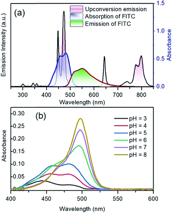
The upconversion emission color can be finely tuned by controlling the concentration and types of rare earth ions. The extended goal of the present work was to utilize the upconversion emission bands as a reference and responsive signals for pH detection. The pH-sensitive moiety FITC was coupled with the nanoparticles for the purpose of designing a self-referenced, ratiometric nanoprobe. The nanoparticles were coated with branched PEI due to its several reported advantages in intracellular applications.35 Firstly, PEI can create a positive surface charge on the nanoparticles, which inevitably enhances the cellular uptake of the nanoparticles. Secondly, the stability of the particles in the colloidal-state is improved with the coating of PEI and helps to increase cellular uptake further. Finally, PEI has a large number of reactive amino groups, which are favourable for conjugating the FITC dye molecules to the surface of the nanoparticles. The FITC structure was activated by the carboxyl groups of EDC, followed by its reaction with the amine groups (PEI) present on the surface of upconverting nanoparticles. Particle size and zeta potential of the PEI functionalized nanoparticles were investigated by dynamic light scattering (DLS) and zeta analyser. Particles were measured in concentrations of 0.05 mg mL−1 in phosphate/citrate-buffer solutions (100 mM, pH 3.0, 6.0, and 8.0). The sizes of the nanoparticles (Fig. S6†) according to light scattering measurements are 107.3 ± 27.8, 1479.7 ± 239.5 and 1661 ± 295 nm for pH 3.0, 6.0 and 8.0, respectively. Due to the protonation of the free amino groups of PEI, the zeta potentials of the PEI-functionalized nanoparticles, as shown in Table S2,† turn out to be more positive with decreasing pH value (+20.91 mV at pH 3), which is accompanied by the increasing colloidal stability of the nanoparticles. The measured values of the PEI-functionalized nanoparticles at various pH are consistent with the reported results in ref. 28. Colloidal stability is a major factor when the UCNPs are employed in an aqueous environment. The positively charged coating of PEI would need to uphold the colloidal stability and prevent agglomeration in the acidic media. We further measured the zeta potential for dye-conjugated UCNPs, showing a decrease in the zeta potential (Table 1) as compared to the PEI-coated nanoparticles. It was expected that functionalization by FITC of PEI-modified nanoparticles would slightly neutralize the positive charges of PEI. The upconversion luminescence from Tm3+ ions at ∼450 and ∼475 nm was entirely overlaid with the broad absorption of FITC molecules (Fig. 4a). The absorption of blue light by FITC molecules changes with pH. As shown in Fig. 4b, absorption at the blue region by the dye molecules decreases with increasing the pH-value from 3 to 8 due to the closing and opening mechanism of the intramolecular spiro-ring. At higher pH-values (deprotonated) the FITC molecules are in open form and show fluorescence properties, while with the introduction of H+ ions it becomes spirocyclic and does not exhibit fluorescence properties. The reversible process of alternation in the molecular structure of FITC is shown in Scheme 2. These structural properties make FITC useful as chemical sensor and pH-sensing moiety.36,37 The upconversion nanoparticles without any FITC conjugation do not show any change in the luminescence intensity at various pH-values. The absorption of FITC (Fig. 4a, blue line) and emission upon 488 nm light excitation (Fig. 4a, red line) along with the upconversion luminescence from the core–shell–shell nanoparticles are shown in Fig. 4a.| pH | 3.0 | 6.0 | 8.0 |
| Zeta (ζ) potential | +15.3 ± 1.2 mV | +0.37 ± 0.31 mV | −5.51 ± 0.43 mV |
| Particle size (nm) | 127.1 ± 31.4 | 1491.5 ± 221.7 | 1808.3 ± 283.5 |
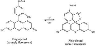 | ||
| Scheme 2 The reversible process of changing the molecular structure of fluorescein-5-isothiocyanate, which is controlled by pH. | ||
The blue-upconversion band is overlapped with the dye-absorption, while some other emission bands located at 643 nm and 802 nm are not absorbed; thus, the changes in the blue upconversion band (474 nm) and NIR upconversion band (802 nm) can be monitored to detect the pH of the system under 980 nm excitation. The pH-dependent absorption responsivity of the nanoparticles has been presented in Fig. 4b. The FITC dye, which is covalently conjugated to the nanoparticle surface, may additionally counteract the fluctuation of luminescence at the intracellular imaging of cells.34
The upconversion luminescence spectra of the FITC-conjugated PEI-core–shell–shell, in sodium phosphate buffer (pH 7–8) or sodium citrate with citric acid buffer (pH 3–6) solutions when the pH was varied from 3 to 8, are shown in Fig. S7a.† It is observed from Fig. S7b† that the band at 474 nm decreases while the 802 nm NIR band remains unchanged, thus it can be considered for use as a reference signal. The absorption by the dye molecules (FITC) at 474 nm is high under acidic conditions and the absorption at the same wavelength decreases with the transition towards the basic regime (higher pH-value). The possibility of the inner-filter effect by re-absorbing the upconversion emission from the particles and the luminescence non-radiative energy transfer from Tm3+ to FITC could both be present in view of the whole mechanism of the hybrid system. The upconversion luminescence lifetime of PEI-coated core–shell–shell nanoparticles at 474 nm was measured and fitted to be 579.68 ± 6.05 μs, while for FITC-conjugated core–shell–shell nanoparticles, it was shortened to 485.84 ± 4.55 μs (Fig. 5). According to the theory in ref. 38, the LRET efficiency was calculated as 16.2%. The formula is given in the ESI.†
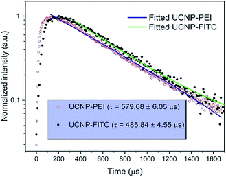 | ||
| Fig. 5 Comparison of transients and fitting curves for the 1G4 → 3H6 transition (474 nm) of Tm3+ in PEI-coated UCNPs and FITC-conjugated UCNP upon excitation at 808 nm. | ||
For the sake of visualization, the ratio of 474 nm to 802 nm is already lower in the pH 3 buffer as compared to the emission in a water environment (Fig. 4a and S7a†). Additionally, in order to figure out the feasibility of using the present system in pH-sensing, we have plotted the ratio of 802 nm to 474 nm. Fig. S7b† shows that the change in their ratio is linear within the pH-values 3–8, which is in the intracellular pH-range in cell organelles. The calculated correlation coefficient is 0.991, which implies that the designed sensor has good preciseness in the detection of pH. If the detection sensitivity is considered as a change in the ratio due to a unit change in pH, the calculated pH-sensitivity is 11.7%.
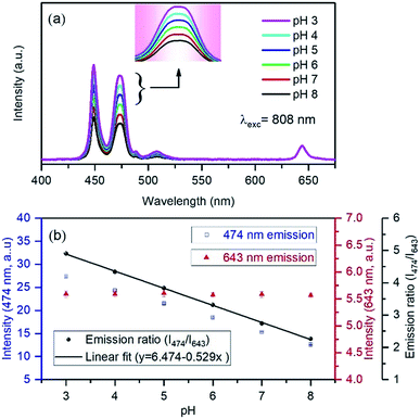
We further carried out pH-dependent measurements upon 808 nm excitation as shown in Fig. 6a. The spectra show that the emission band at 474 nm decreases with increasing pH from 3 to 8, indicating that it can be considered as a pH-responsive signal against the 643 nm reference signal. The linear fitting of the ratio of 474 nm to 643 nm with pH shows high accuracy of sensitivity with the coefficient of correlation as 0.998 (Fig. 6b). Upon 808 nm excitation, the nanoprobe yields 52.9% sensitivity, which represents an excellent result as compared to some previously reviewed pH-sensors.23 The stability is shown in Fig. S8,† in five cycles for each pH, reflecting that FITC-conjugated core–shell–shell UCNPs have good reversibility in the pH range 3–8. Although the variation of blue emission bands is different due to the excitation mechanism pathways in both the systems, the absence of background auto-fluorescence upon NIR light excitation and sufficient LRET between Tm3+ and FITC accounts for the achievement of high detection sensitivity and accuracy in the measurement. The ratiometric technique can minimize the influence of factors of the measurement conditions on the detection accuracy. Additionally, both pH-responsive and reference signals originated from the UCNPs. Therefore, the high dye loading is beneficial for energy transfer and excludes the limitation of the FITC loading, occurring from the self-quenching effect. However, at higher dye-loading, less colloidal stability is expected due to the loss of charged groups at high pH and may degrade the quality of the nanoparticles in their applications. However, it is worth mentioning here that taking the dye emission in the green region into account as a ratiometric parameter may introduce inaccuracy into the measurements, as the Tm3+ ion itself produces an emission band ∼517 nm, which is almost impossible to distinguish from the dye emission (Fig. 3d).
Conclusion
We have developed upconversion nanoparticles through spatial doping of the Tm3+, Yb3+ and Nd3+ ions in the core–shell–shell structure of the NaYF4 matrix. The constructed nanoparticles are not only excitable by 980 nm, but also by 808 nm near-infrared light to bypass the overheating effect. The Nd3+ ions have been utilized in harvesting the 808 nm photons and contribute to the sensitization process with an optimal concentration of 20 mol% in conjunction with 10 mol% Yb3+ ions at the outer shell of the nanoparticles. The immediate layer to the core has solely Yb3+ ions, containing an optimized concentration of 10 mol%. The nanoparticles can circumvent the drawbacks such as UV excitation, auto-fluorescence, photo-bleaching, etc., which are confronted by the down-conversion nanoparticles even while they are attached to organic dye molecules. The pH-dependent experimental results indicate that the upconversion emission itself can be used in pH-sensing in a ratiometric way, even though the dye-emission is overlaid with one of the upconversion emission bands. The synthesized upconversion nanoparticles function as a pH-nanoprobe and exhibit changes in the ratio of the luminescence intensity, i.e., 11.7% and 52.9% in the pH range of 3 to 8 under 980 and 808 nm laser excitations, respectively. The superior design of the nanoparticles and their pH-sensing, as described in this work, would greatly facilitate the applications of the upconversion nanoparticles in further biological applications.Conflicts of interest
There are no conflicts to declare.Acknowledgements
K. T. L. was supported by grants funded by the National Research Foundation (NRF) (NRF-2017R1A2B3005414 and NRF-2016R1D1A1B03931644) of South Korea. This work was also supported by the GRI (GIST Research Institute), 2018, South Korea. M. K. M would like to acknowledge Gibok Lee and Hanyoung Park for fruitful discussion and guidance in synthesizing the upconverting nanoparticles. Authors are thankful to Dr Eun-Jung Jo and Prof. Min-Gon Kim, for extending experimental facilities for the DLS and zeta potential measurements. M. K. M. would like to acknowledge the help of Dr Ranjit De for materials characterizations.Notes and references
- B. Zhou, B. Shi, D. Jin and X. Liu, Nat. Nanotechnol., 2015, 10(11), 924 CrossRef CAS PubMed.
- J. Wang, T. Ming, Z. Jin, J. Wang, L. D. Sun and C. H. Yan, Nat. Commun., 2014, 5, 5669 CrossRef CAS PubMed.
- Y. Liu, Y. Lu, X. Yang, X. Zheng, S. Wen, F. Wang, X. Vidal, J. Zhao, D. Liu, Z. Zhou, C. Ma, J. Zhou, J. A. Piper, P. Xi and D. Jin, Nature, 2017, 543(7644), 229 CrossRef CAS PubMed.
- Y. I. Park, K. T. Lee, Y. D. Suh and T. Hyeon, Chem. Soc. Rev., 2015, 44(6), 1302–1317 RSC.
- Y. I. Park, H. M. Kim, J. H. Kim, K. C. Moon, B. Yoo, K. T. Lee, N. Lee, Y. Choi, W. Park, D. Ling and K. Na, Adv. Mater., 2012, 24(42), 5755–5761 CrossRef CAS PubMed.
- G. Chen, H. Qiu, P. N. Prasad and X. Chen, Chem. Rev., 2014, 114(10), 5161–5214 CrossRef CAS PubMed.
- E. Hemmer, P. Acosta-Mora, J. Méndez-Ramos and S. Fischer, J. Mater. Chem. B, 2017, 5, 4365–4392 RSC.
- J. Zhou, Z. Liu and F. Li, Chem. Soc. Rev., 2012, 41(3), 1323–1349 RSC.
- R. Naccache, F. Vetrone, V. Mahalingam, L. A. Cuccia and J. A. Capobianco, Chem. Mater., 2009, 21(4), 717–723 CrossRef CAS.
- J. C. Boyer, M. P. Manseau, J. I. Murray and F. C. van Veggel, Langmuir, 2009, 26(2), 1157–1164 CrossRef PubMed.
- F. Wang, R. Deng, J. Wang, Q. Wang, Y. Han, H. Zhu, X. Chen and X. Liu, Nat. Mater., 2011, 10(12), 968–973 CrossRef CAS PubMed.
- F. Wang, Y. Han, C. S. Lim, Y. Lu, J. Wang, J. Xu, H. Chen, C. Zhang, M. Hong and X. Liu, Nature, 2010, 463(7284), 1061–1065 CrossRef CAS PubMed.
- F. Vetrone, R. Naccache, V. Mahalingam, C. G. Morgan and J. A. Capobianco, Adv. Funct. Mater., 2009, 19(18), 2924–2929 CrossRef CAS.
- H. S. Mader, P. Kele, S. M. Saleh and O. S. Wolfbeis, Curr. Opin. Chem. Biol., 2010, 14(5), 582–596 CrossRef CAS PubMed; A. Sedlmeier and H. H. Gorris, Chem. Soc. Rev., 2015, 44, 1526–1560 RSC.
- K. Green, K. Huang, H. Pan, G. Han and S. F. Lim, Front. Chem., 2018, 6, 416 CrossRef CAS PubMed; J. Han and K. Burgess, Chem. Rev., 2010, 110, 2709–2728 CrossRef PubMed; K. P. Carter, A. M. Young and A. E. Palmer, Chem. Rev., 2014, 114, 4564–4601 CrossRef PubMed.
- L. Xie, Y. Qin and H. Y. Chen, Anal. Chem., 2012, 84(4), 1969–1974 CrossRef CAS PubMed.
- J. R. Casey, S. Grinstein and J. Orlowski, Nat. Rev. Mol. Cell Biol., 2010, 11(1), 50 CrossRef CAS PubMed.
- H. A. Clark, R. Kopelman, R. Tjalkens and M. A. Philbert, Anal. Chem., 1999, 71(21), 4837–4843 CrossRef CAS PubMed.
- I. L. Medintz, M. H. Stewart, S. A. Trammell, K. Susumu, J. B. Delehanty, B. C. Mei, J. S. Melinger, J. B. Blanco-Canosa, P. E. Dawson and H. Mattoussi, Nat. Mater., 2010, 9(8), 676–684 CrossRef CAS PubMed.
- Y. H. Chan, C. Wu, F. Ye, Y. Jin, P. B. Smith and D. T. Chiu, Anal. Chem., 2011, 83(4), 1448–1455 CrossRef CAS PubMed.
- J. Yan, M. C. Estévez, J. E. Smith, K. Wang, X. He, L. Wang and W. Tan, Nano Today, 2007, 2(3), 44–50 CrossRef.
- D. Wencel, T. Abel and C. McDonagh, Anal. Chem., 2013, 86(1), 15–29 CrossRef PubMed.
- M. K. Mahata, H. Bae and K. T. Lee, Molecules, 2017, 22(12), 2064 CrossRef PubMed.
- L. N. Sun, H. Peng, M. I. J. Stich, D. Achatz and O. S. Wolfbeis, Chem. Commun., 2009, 33, 5000–5002 RSC.
- S. Wilhelm, M. del Barrio, J. Heiland, S. F. Himmelstoß, J. Galbán, O. S. Wolfbeis and T. Hirsch, ACS Appl. Mater. Interfaces, 2014, 6(17), 15427–15433 CrossRef CAS PubMed; M. del Barrio, S. de Marcos, V. Cebolla, J. Heiland, S. Wilhelm, T. Hirsch and J. Galbán, Biosens. Bioelectron., 2014, 59, 14–20 CrossRef PubMed.
- R. Arppe, T. Nareoja, S. Nylund, L. Mattsson, S. Koho, J. M. Rosenholm, T. Soukka and M. Schaferling, Nanoscale, 2014, 6, 6837–6843 RSC; R. J. Meier, J. M. Simbürger, T. Soukka and M. Schäferling, Anal. Chem., 2014, 86, 5535–5540 CrossRef CAS PubMed.
- C. Li, J. Zuo, L. Zhang, Y. Chang, Y. Zhang, L. Tu, X. Liu, B. Xue, Q. Li and H. Zhao, Sci. Rep., 2016, 6, 38617 CrossRef CAS PubMed.
- T. Näreoja, T. Deguchi, S. Christ, R. Peltomaa, N. Prabhakar, E. Fazeli, N. Perälä, J. M. Rosenholm, R. Arppe, T. Soukka and M. Schaferling, Anal. Chem., 2017, 89, 1501–1508 CrossRef PubMed.
- S. Guo, M. K. Tsang, W. S. Lo, J. Hao and W. T. Wong, Nanoscale, 2018, 10(6), 2790–2803 RSC.
- Y. Goh, Y. H. Song, G. Lee, H. Bae, M. K. Mahata and K. T. Lee, Phys. Chem. Chem. Phys., 2018, 20(16), 11359–11368 RSC; F. Wang, D. K. Chatterjee, Z. Li, Y. Zhang, X. Fan and M. Wang, Nanotechnology, 2006, 17(23), 5786 CrossRef CAS.
- X. Xie, N. Gao, R. Deng, Q. Sun, Q. H. Xu and X. Liu, J. Am. Chem. Soc., 2013, 135, 12608–12611 CrossRef CAS PubMed.
- T. Miyakawa and D. L. Dexter, Phys. Rev. B: Solid State, 1970, 1(7), 2961 CrossRef.
- J. Su, F. Song, H. Tan, L. Han, F. Zhou, J. Tian, G. Zhang, Z. Cheng and H. Chen, J. Phys. D: Appl. Phys., 2006, 39(10), 2094 CrossRef CAS.
- L. Wang, Z. Liu, Z. Chen, D. Zhao, G. Qin and W. Qin, Opt. Express, 2011, 19, 25471 CrossRef CAS PubMed.
- T. Näreoja, T. Deguchi, S. Christ, R. Peltomaa, N. Prabhakar, E. Fazeli, N. Perälä, J. M. Rosenholm, R. Arppe, T. Soukka and M. Schäferling, Anal. Chem., 2017, 89(3), 1501–1508 CrossRef CAS PubMed; A. E. Guller, A. Nadort, A. N. Generalova, E. V. Khaydukov, A. V. Nechaev, I. A. Kornienko, E. V. Petersen, L. Liang, A. B. Shekhter, Y. Qian and E. M. Goldys, ACS Biomater. Sci. Eng., 2018, 4(9), 3143–3153 CrossRef.
- Q. A. Best, N. Sattenapally, D. J. Dyer, C. N. Scott and M. E. McCarroll, J. Am. Chem. Soc., 2013, 135(36), 13365–13370 CrossRef CAS PubMed.
- J. Han and K. Burgess, Chem. Rev., 2009, 110(5), 2709–2728 CrossRef PubMed.
- J. B. Pawley, Handbook of Biological Confocal Microscopy, 2006 Search PubMed.
Footnote |
| † Electronic supplementary information (ESI) available. See DOI: 10.1039/c9na00088g |
| This journal is © The Royal Society of Chemistry 2019 |

