 Open Access Article
PTFEP–Al2O3 hybrid nanowires reducing thrombosis and biofouling†
Ayman
Haidar
a,
Awadelkareem A.
Ali
a,
Salih
Veziroglu
 b,
Jacek
Fiutowski
c,
Hermann
Eichler
d,
Isabelle
Müller
d,
Karin
Kiefer
a,
Franz
Faupel
 b,
Markus
Bischoff
e,
Michael
Veith
f,
Oral Cenk
Aktas
 *ab and
Hashim
Abdul-Khaliq
*a
aDepartment of Paediatric Cardiology, Saarland University, Building 9, 66421 Homburg, Germany. E-mail: Hashim.Abdul-Khaliq@uks.eu
bChair for Multicomponent Materials, Institute for Materials Science, Faculty of Engineering, Christian-Albrechts-University of Kiel, Kaiserstr. 2, 24143 Kiel, Germany. E-mail: oca@tf.uni-kiel.de
cMads Clausen Institute, NanoSYD, University of Southern Denmark, Alsion 2, 6400 Sønderborg, Denmark
dInstitute of Clinical Hemostaseology and Transfusion Medicine, Saarland University, Building 1, Ringstr. 52, 66421 Homburg, Germany
eInstitute of Medical Microbiology and Hygiene, Saarland University, Homburg/Saar, 66421, Germany
fINM-Leibniz Institute for New Materials, Campus D2 2, Saarbrücken, 66123, Germany
First published on 24th October 2019
Abstract
Thrombosis and bacterial infection are major problems in cardiovascular implants. Here we demonstrated that a superhydrophobic surface composed of poly(bis(2,2,2-trifluoroethoxy)phosphazene) (PTFEP)–Al2O3 hybrid nanowires (NWs) is effective to reduce both platelet adhesion/activation and bacterial adherence/colonization. The proposed approach allows surface modification of cardiovascular implants which have 3D complex geometries.
Superhydrophobic surfaces with water contact angles (CAs) larger than 150° and slip angles (SAs) less than 10° attract significant attention.1 For attaining such a superhydrophobic surface, both appropriate surface topography and low surface energy should be considered together.2,3 Besides their various technical applications in different areas including water harvesting, microfluidics, oil–water separation, and anti-icing, in recent years, superhydrophobic surfaces have been suggested to be used in cardiac implants (blood-contacting) to reduce the blood–surface interaction and bacterial adhesion.2,4,5
Protein binding, activation of platelets, and resultant formation of thrombi on blood-contacting cardiovascular devices remain the primary technical barriers for the success of these devices.6 In addition, bacterial infection is also a serious risk for cardiovascular implants, where 7.4% of all implanted cardiovascular devices result in bacterial infection.7 Superhydrophobic surfaces are being explored for reduction of thrombus formation by minimizing material–blood interactions. In addition, such surfaces are able to inhibit bacterial adhesion.
Coating a surface composed of micro- and nanoscale topographic features with low surface energy materials (such as polytetrafluoroethylene, silicone, etc.) is a common approach to prepare a superhydrophobic surface.2 While using such structured surfaces to reduce the thrombogenicity of blood-contacting devices and implants, one should also take different matters into account. A surface topography, which reduces the effective surface area accessible to platelets, should be chosen.8 In addition, the surface morphology is also a critical issue and for instance, reducing the adhesion area exposed to individual platelets decreases the thrombogenicity.9 Moreover, high-curvature surfaces are known to induce denaturation of proteins and therefore, less adhesion of platelets.10
Failure of a cardiac device by thrombus formation can be explained by a complex series of interconnected processes which include protein adsorption, adhesion of platelets, thrombin generation, and complement activation11 as presented in Fig. S1.† Therefore, the reduction of protein adhesion on a surface can be an effective strategy to reduce the risk of thrombus formation. Both Wenzel and Cassie states might be effective to reduce surface area and protein adhesion sites. On the other hand, the stability of superhydrophobicity in cardiac devices and implants is a critical matter since blood–surface interaction is a hydrodynamic process rather than a static interaction.12 In the Cassie state, air pockets trapped between micro and nanoscale surface structures provide a more stable superhydrophobicity in comparison to the Wenzel state.13 Recently we have shown that the lifetime of such air pockets can be as long as several weeks and they can withstand high pressures reaching up to 150 Pa.14 In general, the air has a lower viscosity in comparison to water; therefore the Cassie state can cause significant slip over the surface preventing platelet adhesion.15
In addition to topography, surface chemistry also plays a major role in achieving superhydrophobicity. The surface chemistry becomes more critical in the case of using such superhydrophobic surfaces in blood-contacting devices and implants. In principle, both low surface energy and biocompatibility should be considered for designing blood-contacting surfaces. Polytetrafluoroethylene (PTFE) is one of the most commonly used low surface energy materials in vascular products such as angioplasty catheters, guide-wires, stent grafts, stents, and vena cava filters.16 Recently a new type of fluorinated polymer has been reported as non-thrombotic in cardiac implants. Here, a water-repellent state was achieved by the slippery liquid-infused porous surface (SLIPS) approach, in which a porous surface is covered with an immiscible perfluorocarbon liquid.5,17 This was accomplished by covalently binding a molecular perfluorocarbon layer, or tethered perfluorocarbon, on the material surface and then coating it with a freely mobile layer of liquid perfluorocarbons. On the other hand, reported CAs and the hysteresis are both low. Here, one of the main uncertainties with this surface is whether the presence of a high amount of fluorine in the cardiac system (since the SLIPS contains a large amount of fluorinated polymer) might lead to a long-term side effect.
Fluorinated polyphosphazenes (with an inorganic backbone of alternating phosphorus and nitrogen atoms and organic side groups) have been accepted as alternative polymers for blood-contacting surfaces due to their inherent hydrophobicity with proven biocompatibility in preclinical and clinical settings.18 In a porcine model, PTFEP-coated stents exhibited low thrombogenicity in coronary arteries.19 Further studies provided promising results by the reduction of not only stent thrombogenicity but also in-stent stenosis by applying PTFEP coating on stents.20 On the other hand, most of the studies on PTFEP fail to conclude whether only physicochemical properties of PTFEP coating or additional surface characteristics (topography and roughness) play a role in reducing thrombogenicity and bacterial infection. Most of these studies report the use of PTFEP as a smooth layer but applying low surface energy materials as a plain coating on smooth surfaces can enhance the non-wettability theoretically up to a CA of 120°.2,21
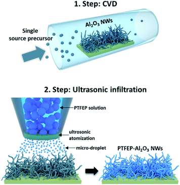
In this study, the synergetic effect of the substrate topography and superior properties of PTFEP was used to develop a coating for next generation cardiovascular implants. A novel chemical vapor deposition (CVD) method (using the single-source-precursor concept as described elsewhere)22 and ultrasonic infiltration technique (details of processes are given in the ESI†) were used to fabricate a superhydrophobic hybrid coating, fluorinated phosphazene (PTFEP)–aluminum oxide (Al2O3) nanowires (NWs, which are composed of an aluminum core and surrounding stable aluminum oxide shell), for cardiovascular implants.22 The prepared surface exhibited an extremely low solid–liquid interaction for both Ringer (used as an artificial blood model) and protein plasma fraction (PPF) solutions. 10 μL drops of these solutions easily rolled-off the prepared surface at inclination angles <1° (Fig. S2 and Video S1†). In order to achieve such a repelling effect, tangled Al2O3 nanowires (NWs) were deposited first on a glass substrate using the single source precursor (SSP) route.23 Next, the inorganic polymer, poly bis(2,2,2-trifluoroethoxy)phosphazene (PTFEP), was infiltrated by using an ultrasonic nozzle system (converting high frequency sound waves into mechanical energy that is transferred into a liquid, creating standing waves) into Al2O3 NWs (as schematically explained in Fig. 1). Basically, ultrasonic sound waves atomized the PTFEP solution into microscale droplets, and this led to a homogenous distribution and even infiltration of the PTFEP solution into the CVD driven nanoporous surface. Such a controlled and precise infiltration process kept the nanoporous morphology intact which is necessary to achieve superhydrophobicity.
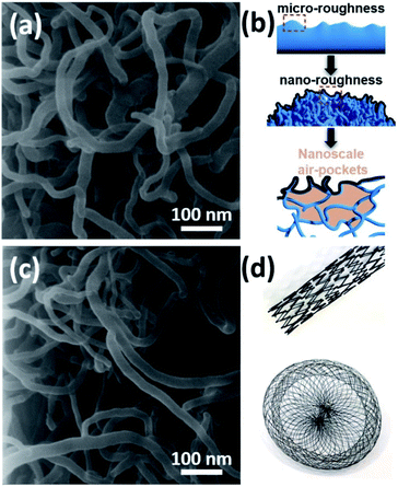
Basically, the deposited layer consists of randomly grown and tangled Al2O3 NWs where the diameter of each NW is around 15–20 nm (Fig. 2a). The deposition temperature and time play a major role in the final surface morphology as shown previously.22 Basically, increasing the substrate temperature promotes the nucleation and the growth of Al2O3 NWs. On the other hand, since the one dimensional (1D) growth mechanism in the case of Al2O3 NWs is different from a typical vapor–liquid–solid (VLS) approach, the initial substrate temperature also affects the diameter of the deposited Al2O3 NWs. At prolonged deposition periods, it was observed that the intersected Al2O3 NWs started coalescing and bundling together. This smoothed the over-all surface morphology, enhancing the solid–liquid contact area. Therefore, we preferred applying a moderate deposition temperature of around 500 °C (to maintain a diameter size of 10–20 nm) and an ultra-short deposition time (a few minutes) to achieve a reduced effective contact area by considering our previous process parameters.24,25 This led to a surface coverage of 38%, calculated by using a grayscale HIM image recorded at low magnification as explained elsewhere.26 For achieving a homogenous deposition within a few minutes, the precursor flow was increased by heating it to 70–75 °C and a semi-batch deposition process was used with help of an automated valve system which was opened–closed every 10 seconds regularly. Since the precursor is in the solid state, the flow rate is very sensitive to the temperature of the environment, and at room temperature, the flow rate is very limited.22 This induced a dual-scale roughness (micro- and nanoscale) and formation of nanoscale air-pockets as schematically shown in Fig. 2b. In the second step, the use of an ultrasonic nozzle system led to the atomization (due to ultrasonic vibrations within the nozzle) and homogenous distribution of PTFEP solution in 3D structures, which was effective to keep the so-called air-pockets intact (Fig. 2c). Basically, such nanoscale air-pockets (also known as nanoscale plastrons) with pronounced hierarchical surface roughness (bundles of Al2O3 NWs: microscale roughness and tangled/intersected Al2O3 NWs: nanoscale roughness) form a stable air cushion within the deposited layer that leads to extremely small overall contact area between the surface and the liquid (water, Ringer solution, PPF solution and blood).5
In helium ion microscopy (HIM) images recorded at a lower magnification, one can see microscale details of the surface which exhibits local bumps and valleys due to tangled and highly intersected Al2O3 NWs (Fig. S3a–d†). When we look closer into such bumps/valleys, a secondary roughness can be clearly seen. High magnification HIM images revealed the presence of both nanoscale roughness and nanoscale air pockets (Fig. S4a–c†). The tangled geometries of Al2O3 NWs led to several cross-cuts and therefore the formation of nanoscale air-pockets (Fig. 2b). The combination of dual-scale roughness and nanoscale air-pockets promotes low liquid–solid interaction. Our CVD process allows using such hierarchical structures in various types of cardiovascular implants which have extremely complicated 3D geometries as shown in Fig. 2d.
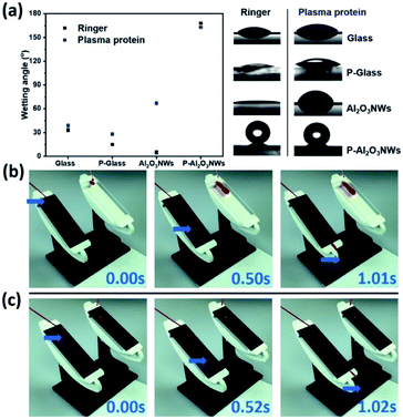
CAs on PTFEP–Al2O3 NWs were measured by the sessile droplet method using Ringer and PPF solutions. The advancing CA for PTFEP–Al2O3 NWs was 168 ± 1° and the receding CA was 166 ± 1° (Fig. 3a) in the case of the Ringer solution. For the smooth PTFEP surface (coated on glass) the advancing CA was 15 ± 1° and the receding CA was 12 ± 2°. It is worth mentioning that the pristine (non-modified with PTFEP) Al2O3 NWs were not hydrophobic at all (exhibiting a CA of 5 ± 2°). The HIM images confirmed that the surface morphology stayed almost intact after the infiltration of PTFEP using an ultrasonic nozzle system (shown schematically in Fig. S5†). When we put a drop of PPF solution on PTFEP–Al2O3 NWs, the advancing CA was 163 ± 1° and the receding contact angle was 161 ± 2°.
We examined the interaction of human blood on the prepared PTFEP–Al2O3 NW surfaces by monitoring a drop of human blood with the help of an ultrafast video camera (complete human blood was provided by healthy donors. Prior to the sample being taken, informed consents were obtained from human participants of this study. This research has been approved by Saarland University Hospital Research Ethics Committee with an Approval ID: 90/19). It is clear from the recorded images (Fig. 3b and Video S2†) that there is no visible trace of blood on the superhydrophobic surface while a large blood trail was left behind on the control surface (smooth glass). As shown from the recorded video images, the static contact angle of a 25 μL blood droplet on the PTFEP–Al2O3 NW surface was 160 ± 3° as compared to 30 ± 2° on the control (smooth glass) surface. Fig. 3c and Video S3† show the significant difference between blood droplets sliding on pristine (without PTFEP) Al2O3 NW and PTFEP–Al2O3 NW substrates tilted to 35°. From this, it is clear that not only the surface morphology but also the combination of nano-porous (dual-scale roughness and air-pockets) nature and the low surface energy layer impacts significant blood repellency on the surface and enables blood transportation without macroscopic loss. Repeated wetting analyses showed that the prepared PTFEP–Al2O3 NWs exhibited almost the same level of hydrophobicity even after 90 days, which may be attributed to the covalently bonded PTFEP molecules on Al2O3.2
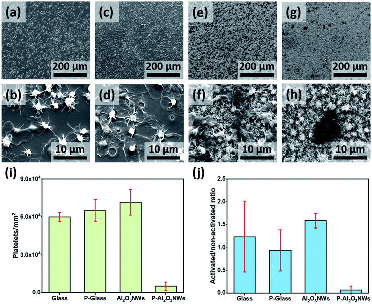
Platelet spreading and aggregation are basic markers of platelet activation and have been linked to thrombotic events. Therefore, we examined platelet response on the PTFEP–Al2O3 NW substrate by immediate perfusion of the surface with whole blood obtained directly from a volunteer donor (see details in the ESI†). The purpose of using the whole blood is to mimic the physiological response of whole blood with all its contents including, blood cells, proteins and coagulation factors for immediate contact with artificial surfaces, which results in thrombus formation.27 Four different samples, glass (control), PTFEP–glass (PTFEP coated), Al2O3 NWs and PTFEP–Al2O3 NWs, were inserted in a specially designed holder and then the holder was coupled to a closed flow system perfused using a diagonal small neonatal pump (Medos Gmbh-Germany) with a volume capacity of 16 mL (Fig. S6†). All samples were inserted in the connecting piece between the two ends of a small circuit perfused using the diagonal pump. The perfusion of the coated samples was started at 25 °C for 10 min at a flow rate of 1500 rpm. Afterward, each surface was examined by scanning electron microscopy (SEM) to observe the platelet adhesion and aggregation behavior. A high platelet adhesion was observed on the control substrate (smooth glass) as presented in Fig. 4a. As shown in Fig. 4b at a higher magnification we observed round shaped platelets and the fibrin development around the platelet body which clearly indicates the strong activation of adhered platelets. Such an aggregation of platelets on glass-like surfaces is well known as previously shown by Baker-Groberg et al.28 For comparison, the platelet response on the PTFEP modified glass substrate was monitored as shown in Fig. 4c.
At first sight (low magnification), no significant difference was observed between the bare glass and PTFEP–glass substrates in terms of platelet adhesion. On the other hand, at a higher magnification, we observed a larger amount of fibrin spread around the platelet body revealing a high level of platelet activation (Fig. 4d). This indicates that PTFEP, when deposited on glass, triggers thrombus formation, which is in contrast to a former study.19 After screening the effect of PTFEP on platelet adhesion and -activation we performed similar analyses on pristine and PTFEP modified Al2O3 NWs. It was observed that platelets were highly adhering (even higher than those observed on glass and PTFEP–glass substrates) on pristine Al2O3 NW surfaces (Fig. 4e). Al2O3 NWs were previously presented as a biocompatible surface and this may explain why the platelets had high tendency to adhere on them.23,29 Additionally, Fig. 4f shows the complete activation of the platelets on pristine Al2O3 NWs. This phenomenon is well known on highly rough surfaces, where fibrinogen adsorption is induced leading to higher activation and strong aggregation of the platelets.30 Moreover, the stiffness and thickness of the surface matrix are known to play a major role in platelet aggregation and activation.31 This may explain the higher number of activated and aggregated platelets on the pristine Al2O3 NWs in comparison to the glass substrate. After PTFEP modification platelet adhesion was extremely reduced, and only a few activated platelets were observed on the entire PTFEP–Al2O3 NWs (Fig. 4g and h).
The number of platelets adhering to each test surface was counted by using ImageJ software. Each sample was divided into 10 defined fields where images were taken, and platelets were counted. The experiment was repeated three times (n = 3). The activation and aggregation of platelets were analyzed by calculating their spread area using a one tailed t-test (Microsoft Excel v.16.16.8.) as presented by Radmacher et al.32Fig. 4i shows an extremely low number of platelets adhering on PTFEP–Al2O3 NWs in comparison to other substrates (p < 0.01). There was a slight difference in the number of platelets attached to pristine and PTFEP modified glass (5.99 ± 0.34 × 104 mm−2 and 6.48 ± 0.87 × 104 mm−2, respectively). The number of platelets on PTFEP–Al2O3 NWs (0.51 ± 0.03 × 104 mm−2) was significantly low compared to the number of platelets attached to pristine Al2O3 NWs (7.15 ± 1.02 × 104 mm−2). When assessing the anti-thrombogenic potential of a surface, in addition to platelet attachment, platelet activation should also be considered. It has been shown that although the surface of a material may not support significant platelet adhesion, platelet activation may still occur.11 In general, morphological changes are one of the most commonly used criteria for assessment of platelet activation. Platelets, which remain inactivated, have a perfect lens shape and their diameter mostly stays in the 2–3 μm range.33–35 During the activation stage, platelets exhibit a more spherical shape and formation of tiny pseudopodia is observed. This is followed by development of fully spread pseudopodia structures. Based on this we tried to reveal the ratio of the activated platelets on the prepared surfaces as shown in Fig. 4j. After the exposure of platelets to test surfaces, PTEFP-Al2O3 NWs exhibited an extremely low platelet activation ratio, while other tested surfaces activated the adherent platelets efficiently. These findings show that PTEFP-Al2O3 NWs do not promote platelet adhesion and activation, which are important first steps in thrombosis formation. Yet the PTEFP-Al2O3 NWs are likely to reduce thrombus formation, still cytocompatibility tests were critical to detect whether our surface modification may exert a relevant cytotoxic effect on host tissue. Therefore, we studied the mediated-toxicity and the metabolic activity of human cardiomyocytes (HCM) on the prepared surfaces using LDH and WST-1 assays, respectively. Both assays did not show any significant difference between tested surfaces (Fig. S7†), indicating that the effectiveness of PTEFP-Al2O3 NWs in the reduction of platelet adhesion and activation cannot be attributed to toxic reactions.
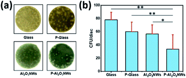
In addition to the risk of thrombus formation and secondary obstruction on vascular devices, bacterial adhesion colonization leading septic complications associated with implantation of intravascular devices may present a rare but serious complication after percutaneous implantation of cardiovascular devices. Superhydrophobic surfaces have been suggested as an alternative to antibiotics and biocides to reduce or even prevent bacterial colonization of implanted medical devices.36 To test the impact of our surface modifications on bacterial adhesion, we incubated these surfaces with Staphylococcus epidermidis in a microtiter plate based adhesion assay. Briefly, discs (8 mm diameter) of glass, PTFEP–glass, pristine Al2O3 NWs, and PTFEP–Al2O3 NWs were fixed on the bottom of a 24-well plate and incubated for 30 min in phosphate buffered saline (PBS) solution containing 1 × 10⁴ colony forming units (CFU) of S. epidermidis strain RP62a. Discs were afterwards washed twice with PBS, placed upside-down on Luria–Bertani agar plates and incubated for 48 h at 37 °C. Representative images of S. epidermidis colonies observed on test surfaces after 48 h of incubation at 37 °C are shown in Fig. 5a.
Quantification of CFU rates formed on the test surfaces demonstrated that PTFEP–Al2O3 NW discs displayed the lowest colonization rates (Fig. 5b). Notably, neither discs with a smooth PTFEP layer deposited on the glass substrate (P-Glass) nor discs composed of pristine Al2O3 NWs displayed marked reductions in colonization rates when compared to bare glass, indicating that the reduced bacterial adhesion on PTFEP–Al2O3 NWs required the synergetic effect of both, unique topography of Al2O3 NWs, and the low surface energy of the PTFEP layer.
Conclusions
In summary, synergy by combining superior topographic characteristics of Al2O3 NWs (without any toxicity) and low surface energy of PTFEP was proposed to reduce thrombus formation and bacterial adhesion for cardiovascular implants. The prepared Al2O3 NWs exhibited superior topographic features, which promote superhydrophobicity. The deposited Al2O3 NWs showed a dual-scale roughness (bundles of Al2O3 NWs: microscale roughness and tangled/intersected Al2O3 NWs: nanoscale roughness). Basically, nanoscale air-pockets with pronounced hierarchical dual-scale surface roughness form a stable air cushion within the deposited layer that leads to extremely small overall contact area between the surface and blood in contact below the liquid. This reduced contact area and now-wetting nature prevent platelet adhesion and activation. The same surface also exhibits a sound anti-biofouling effect. The applicability of the proposed approach to 3D complex geometries makes it a strong candidate for new generation coatings for cardiovascular devices and implants in children and adults with cardiovascular diseases.Conflicts of interest
There are no conflicts to declare.Acknowledgements
The authors would like to thank Deutsche Herzstiftung and Herzkrankes Kind Homburg/Saar for their invaluable support.References
- Q. F. Xu, Y. Liu, F. J. Lin, B. Mondal and A. M. Lyons, ACS Appl. Mater. Interfaces, 2013, 5, 8915–8924 CrossRef CAS PubMed.
- A. A. Ali, A. Haidar, O. Polonskyi, F. Faupel, H. Abdul-Khaliq, M. Veith and O. C. Aktas, Nanoscale, 2017, 9, 14814–14819 RSC.
- X.-M. Li, D. Reinhoudt and M. Crego-Calama, Chem. Soc. Rev., 2007, 36, 1350 RSC.
- X. Zhang, F. Shi, J. Niu, Y. Jiang and Z. Wang, J. Mater. Chem., 2008, 18, 621–633 RSC.
- V. Jokinen, E. Kankuri, S. Hoshian, S. Franssila and R. H. A. Ras, Adv. Mater., 2018, 30, 1705104 CrossRef PubMed.
- E. J. Falde, S. T. Yohe, Y. L. Colson and M. W. Grinstaff, Biomaterials, 2016, 104, 87–103 CrossRef CAS PubMed.
- R. O. Darouiche, N. Engl. J. Med., 2004, 350, 1422–1429 CrossRef CAS PubMed.
- S. Movafaghi, V. Leszczak, W. Wang, J. A. Sorkin, L. P. Dasi, K. C. Popat and A. K. Kota, Adv. Healthcare Mater., 2017, 6, 1700647 CrossRef PubMed.
- L. Chen, D. Han and L. Jiang, Colloids Surf., B, 2011, 85, 2–7 CrossRef CAS PubMed.
- P. Roach, D. Farrar and C. C. Perry, J. Am. Chem. Soc., 2006, 128, 3939–3945 CrossRef CAS PubMed.
- I. H. Jaffer, J. C. Fredenburgh, J. Hirsh and J. I. Weitz, J. Thromb. Haemostasis, 2015, 13, S72–S81 CrossRef PubMed.
- N. Zaidi, L. V. Mclntire, D. H. Farrell and P. Thiagarajan, Transfus. Med. Rev., 1997, 11, 150–151 Search PubMed.
- D. Y. Kim, J. G. Lee, B. N. Joshi, S. S. Latthe, S. S. Al-Deyab and S. S. Yoon, J. Mater. Chem. A, 2015, 3, 3975–3983 RSC.
- O. C. Aktas, S. Schröder, S. Veziroglu, M. Z. Ghori, A. Haidar, O. Polonskyi, T. Strunskus, K. Gleason and F. Faupel, Adv. Mater. Interfaces, 2019, 6, 1801967 CrossRef CAS.
- S. P. Jackson, W. S. Nesbitt and E. Westein, J. Thromb. Haemostasis, 2009, 7, 17–20 CrossRef CAS PubMed.
- M. T. Lam and J. Wu, Expert Rev. Cardiovasc. Ther., 2012, 10, 1039–1049 CrossRef CAS PubMed.
- D. C. Leslie, A. Waterhouse, J. B. Berthet, T. M. Valentin, A. L. Watters, A. Jain, P. Kim, B. D. Hatton, A. Nedder, K. Donovan, E. H. Super, C. Howell, C. P. Johnson, T. L. Vu, D. E. Bolgen, S. Rifai, A. R. Hansen, M. Aizenberg, M. Super, J. Aizenberg and D. E. Ingber, Nat. Biotechnol., 2014, 32, 1134–1140 CrossRef CAS PubMed.
- M. Deng, S. G. Kumbar, Y. Wan, U. S. Toti, H. R. Allcock and C. T. Laurencin, Soft Matter, 2010, 6, 3119–3132 RSC.
- C. Henn, S. Satzl, P. Christoph, P. Kurz, B. Radeleff, U. Stampfl, S. Stampfl, I. Berger and G. M. Richter, J. Vasc. Interv. Radiol., 2008, 19, 427–437 CrossRef PubMed.
- U. Stampfl, C. M. Sommer, H. Thierjung, S. Stampfl, R. Lopez-Benitez, B. Radeleff, I. Berger and G. M. Richter, Cardiovasc. Interv. Radiol., 2008, 31, 1184–1192 CrossRef PubMed.
- T. Nishino, M. Meguro, K. Nakamae, M. Matsushita and Y. Ueda, Langmuir, 2002, 15, 4321–4323 CrossRef.
- M. Veith, J. Lee, M. Martinez Miró, C. K. Akkan, C. Dufloux and O. C. Aktas, Chem. Soc. Rev., 2012, 41, 5117–5130 RSC.
- K. Kiefer, J. Lee, A. Haidar, M. Martinez Miró, C. Kaan Akkan, M. Veith, O. Cenk Aktas and H. Abdul-Khaliq, Nanotechnology, 2014, 25, 495101 CrossRef PubMed.
- M. Veith, E. Sow, U. Werner, C. Petersen and O. C. Aktas, Eur. J. Inorg. Chem., 2008, 2008, 5181–5184 CrossRef.
- J. Lee, M. M. Miró, C. K. Akkan, A. Haidar, W. Metzger, L. K. Schwarz, V. Zaporojtchenko, K. H. Schäfer, H. Abdul-Khaliq, M. Veith and C. Aktas, J. Biomed. Nanotechnol., 2013, 9, 295–298 CrossRef CAS PubMed.
- M. M. Miró, M. Veith, J. Lee, F. Soldera, F. Mücklich, R. Bennewitz and C. Aktas, J. Microsc., 2015, 258, 113–118 CrossRef PubMed.
- M. Tomaiuolo, L. F. Brass and T. J. Stalker, Interventional Cardiology Clinics, 2017, 6, 1–12 CrossRef PubMed.
- S. M. Baker-Groberg, F. A. Cianchetti, K. G. Phillips and O. J. T. McCarty, Cell. Mol. Bioeng., 2014, 7, 285–290 CrossRef CAS PubMed.
- W. Metzger, B. Schwab, M. M. Miro, S. Grad, A. Simpson, M. Veith, G. Wennemuth, V. Zaporojtchenko, S. Verrier, J. S. Hayes, M. Bubel, T. Pohlemann, M. Oberringer and C. Aktas, J. Biomed. Nanotechnol., 2014, 10, 831–845 CrossRef CAS PubMed.
- J. Linneweber, P. M. Dohmen, U. Kerzscher, K. Affeld, Y. Nosé and W. Konertz, Artif. Organs, 2007, 31, 345–351 CrossRef PubMed.
- T.-H. Nguyen, R. Palankar, V.-C. Bui, N. Medvedev, A. Greinacher and M. Delcea, Sci. Rep., 2016, 6, 25402 CrossRef CAS PubMed.
- M. Radmacher, M. Fritz, C. M. Kacher, J. P. Cleveland and P. K. Hansma, Biophys. J., 1996, 70, 556–567 CrossRef CAS PubMed.
- W. Okrój, M. Walkowiak-Przybyło, K. Rośniak-Bąk, L. Klimek and B. Walkowiak, Acta Bioeng. Biomech., 2009, 11, 45–49 Search PubMed.
- M. Kuwahara, M. Sugimoto, S. Tsuji, H. Matsui, T. Mizuno, S. Miyata and A. Yoshioka, Arterioscler., Thromb., Vasc. Biol., 2002, 22, 329–334 CrossRef CAS PubMed.
- P. Yang, N. Huang, Y. Leng, J. Chen, R. K. Fu, S. C. Kwok, Y. Leng and P. Chu, Biomaterials, 2003, 24, 2821–2829 CrossRef CAS PubMed.
- X. Zhang, L. Wang and E. Levänen, RSC Adv., 2013, 3, 12003–12020 RSC.
Footnote |
| † Electronic supplementary information (ESI) available. See DOI: 10.1039/c9na00436j |
| This journal is © The Royal Society of Chemistry 2019 |

