Continuous mesoporous Pd films with tunable pore sizes through polymeric micelle-assisted assembly†
Muhammad
Iqbal
 abc,
Yusuf Valentino
Kaneti
 *a,
Kenji
Kashimura
d,
Masahiro
Yoshino
d,
Bo
Jiang
 a,
Cuiling
Li
 a,
Brian
Yuliarto
 b,
Yoshio
Bando
 aef,
Yoshiyuki
Sugahara
 c and
Yusuke
Yamauchi
 *gh
*gh
aInternational Research Center for Materials Nanoarchitectonics (WPI-MANA), National Institute for Materials Science (NIMS), 1-1 Namiki, Tsukuba, Ibaraki 305-0044, Japan. E-mail: KANETI.Valentino@nims.go.jp
bDepartment of Engineering Physics and Research Center for Nanoscience and Nanotechnology, Institute of Technology Bandung, Bandung 40132, Indonesia
cDepartment of Nanoscience and Nanoengineering, Faculty of Science and Engineering, Waseda University, 3-4-1 Okubo, Shinjuku, Tokyo 169-8555, Japan
dR&D Division, Yoshino Denka Kogyo Inc., Saitama 342-0008, Japan
eInstitute of Molecular Plus, Tianjin University, Tianjin 300072, P. R. China
fAustralian Institute for Innovative Materials (AIIM), The University of Wollongong, North Wollongong, NSW 2500, Australia
gSchool of Chemical Engineering and Australian Institute for Bioengineering and Nanotechnology (AIBN), The University of Queensland, Brisbane, QLD 4072, Australia. E-mail: y.yamauchi@uq.edu.au
hDepartment of Plant & Environmental New Resources, Kyung Hee University, 1732 Deogyeong-daero, Giheung-gu, Yongin-si, Gyeonggi-do 446-701, South Korea
First published on 26th February 2019
Abstract
Mesoporous metallic films have shown enhanced catalytic performance for numerous electrocatalytic applications, such as electrooxidation of liquid fuels (ethanol, methanol, etc.) and biomolecules (glucose, maltose, etc.). Previously, our group has demonstrated the feasible fabrication of mesoporous Pd thin films using low-molecular-weight surfactants as templates (e.g. C. Li, B. Jiang, N. Miyamoto, J. H. Kim, V. Malgras and Y. Yamauchi, J. Am. Chem. Soc. 2015, 137, 11558–11561). However, the resulting pore size is typically limited to 2–10 nm, which may be disadvantageous for practical applications. This work demonstrates a breakthrough in the fabrication of mesoporous palladium (Pd) films with larger and tunable pore sizes from 14 to 41 nm using polymeric micelle-assisted electrochemical deposition. The average pore size of the resulting mesoporous Pd films can be conveniently tuned by employing block copolymers (PS-b-PEO) with different molecular weights. Mesoporous Pd films with larger average pore sizes exhibit higher mass activities for the ethanol oxidation reaction (EOR) than those with smaller average pore sizes along with superior electrocatalytic stability compared to commercially available Pd catalyst. It is anticipated that the proposed soft-templated approach can be extended to the preparation of other mesoporous metallic films for various electrocatalytic applications.
Conceptual insightsThe preparation of traditional mesoporous metallic films generally relies on hard-templating methods. The direct deposition of mesoporous films with metallic frameworks via soft-templating methods is limited to small pores, which are unsuitable for practical applications. Polymeric micelles with large molecular weights can provide mesoporous metallic films with larger open pores. The important factors in the polymeric micelle-assisted electrodeposition of mesoporous metallic films are the appropriate interactions between the metal ion complexes and the outer shell of the micelles in aqueous electrolyte solutions and the appropriate applied deposition potential. Mesoporous metallic films with larger pores possess higher mass-normalized electrochemically active surface areas (ECSAs) compared to those with non-porous metallic films and commercial metallic catalyst. Moreover, the films with larger pores can allow the guest molecules to access the inner region and the products to go out to the outer region more efficiently. In addition, their larger open pores offer more abundant accessible active sites and their unique 3D structure provides better stability against deformation during the electrocatalytic reaction. |
Introduction
Nanoporous materials offer excellent functionalities for a wide variety of applications, such as wastewater remediation, biomedical/drug delivery, and catalysis, due to their high surface area, large pore volume, and modifiable surface properties.1–5 Mesoporous materials (pore size: 2–50 nm) can generally be prepared through two main methods: hard-templating and soft-templating. Among the two methods, the soft-templating method is the less complicated approach as the template removal does not require complex procedures and the use of strong acid or base.6–8 In the soft-templating method, the pore size and structure of the resulting mesoporous materials can be tuned by controlling the assembly of surfactants or block copolymer micelles in the reaction solution. In particular, the assembly of large micelles can facilitate the formation of larger open pores. However, mesoporous materials with larger pores are still limited to carbon, silica, metal oxides, and organosilicates. Until now, there have been limited studies on the preparation of mesoporous metals with larger mesopores by soft-templating methods.9–13 Mesoporous metals (especially noble metals) with large open pores are expected to exhibit enhanced performance toward many important applications, including electrocatalysis.14,15 Yet, it is still difficult to prepare mesoporous noble metals with large mesopores using the soft-templating method.Among noble metals, platinum (Pt) is known as the most catalytically active element. However, its rarity in nature has limited its wider application, and hence many researchers are now seeking to reduce its consumption or to replace it altogether with cheaper materials. As the second most catalytically active element, palladium (Pd) is more abundant and possesses a similar structure to Pt. As such, it has great potential to replace (substitute) completely or partially Pt in various catalytic reactions.16–18 In fact, previous reports have demonstrated the excellent catalytic activity of Pd toward the oxidation of hydrogen or liquid fuels as well as its high selectivity toward the hydrogenation of acetylene.19,20
In recent years, several studies have been reported on the preparation of mesoporous metals by using polymeric micelles assembly. Both mesoporous Pd particles and films have also been reported; however, the pore size was limited to 2–10 nm.21–24 In these studies, cationic and non-ionic surfactants with relatively short chain lengths were used to prepare mesoporous metals. Block copolymers with large chain lengths (high molecular weights) can form larger micelles in solution with diameters ≥10 nm. The selection of a suitable hydrophobic moiety for the block copolymer is critical for ensuring stable interactions between the block copolymer and the Pd ion complexes in water, which in turn will assist the formation of mesoporous Pd films with larger mesopores.
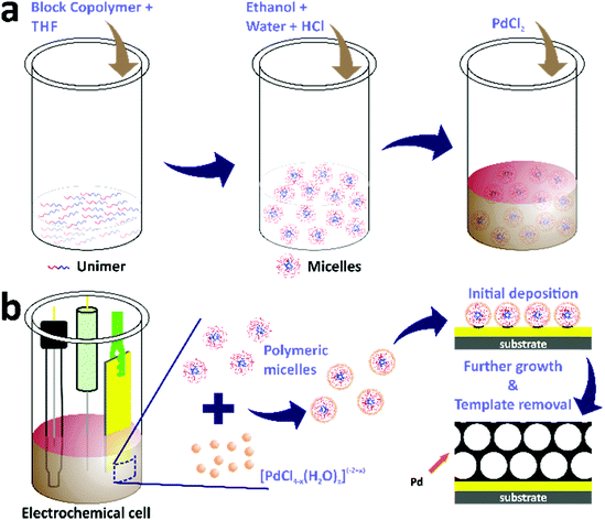
Herein, we report the facile preparation of mesoporous Pd films with controllable large pores using polymeric micelle-assisted electrochemical deposition. The pore size tuning was achieved by utilizing block copolymers with different molecular weights. The electrolyte solution consisted of a Pd precursor and micelles dissolved in a mixture of tetrahydrofuran (THF), ethanol, hydrochloric acid, and water. In this reaction system, THF played an important role in promoting the dissolution of the block copolymer into free unimers in the solution. Subsequent additions of ethanol and water induced the micellization of the block copolymer. The mesoporous Pd films deposited from electrolyte solutions containing PS(5000)-b-PEO(2200), PS(18000)-b-PEO(7500), and PS(63000)-b-PEO(26000) were denoted as meso Pd-2.2, meso Pd-7.5, and meso Pd-26, respectively (the molecular weight for each block is shown in parentheses). To probe the electrocatalytic performance of the as-prepared mesoporous Pd films, ethanol oxidation was selected as the model reaction. The electrocatalytic tests revealed that the as-obtained mesoporous Pd films displayed high electrocatalytic performance for ethanol oxidation, owing to their large surface-active area, open accessible pores, and stable mesoporous structure.
Experimental
Chemicals
Block copolymers, polystyrene-b-poly(ethylene oxide) (PS-b-PEO) with three different molecular weights, were purchased from Polymer Source. Tetrahydrofuran (THF), palladium(II) chloride, and ethanol were obtained from Nacalai Tesque, Inc. Hydrochloric acid, sulfuric acid, and potassium hydroxide were purchased from Wako Chemicals. All the chemicals were used without prior treatment. The double distilled water was obtained through a Merck Milli-Q® water purification system.Electrochemical deposition of mesoporous Pd films
The electrochemical deposition of mesoporous Pd films was carried out in electrochemical cells containing electrolyte solutions with three standard electrodes (Scheme 1). First, the electrolyte solutions were prepared by dissolving 4 mg of block copolymers in THF through sonication for 5 minutes. The amount of THF was different for each block copolymer, i.e. 0.08 mL, 0.6 mL, and 1.6 mL for PS(5000)-b-PEO(2200), PS(18000)-b-PEO(7500), and PS(63000)-b-PEO(26000), respectively. Ethanol (1.5 mL) was then added into the above solutions, followed by the addition of 0.08 mL of 2 M HCl along with distilled water to make the total volume of each electrolyte solution be 3.75 mL. Finally, 0.25 mL of 80 mM PdCl2 aqueous solution was added into each electrolyte solution. The electrodes for the electrochemical deposition consisted of a gold-coated silicon substrate, Ag/AgCl, and Pt wire as the working, reference, and counter electrodes, respectively. The working electrode had dimensions of 0.3 cm × 1.5 cm with a deposition area of 0.3 cm × 0.6 cm (0.18 cm2). The electrochemical deposition from each block copolymer-containing electrolyte solution was carried out using the amperometric i–t technique with an electrochemical workstation (CHI 842B model, USA) at a constant applied potential of 0.0 V (vs. Ag/AgCl). The template removal was subsequently carried out by first rinsing the films with distilled water followed by blowing under nitrogen gas flow and subsequent immersion in THF overnight. The samples electrodeposited from electrolyte solutions containing PS(5000)-b-PEO(2200), PS(18000)-b-PEO(7500), and PS(63000)-b-PEO(26000) were denoted as meso Pd-2.2, meso Pd-7.5, and meso Pd-26, respectively. The growth rates were determined by cross-sectional SEM and TEM observation, and their values were 0.42 nm s−1 for meso Pd-2.2, 0.26 nm s−1 for meso Pd-7.5 and 0.24 nm s−1 for meso Pd-26.Characterization
Scanning electron microscopy (SEM) images of the deposited Pd films were obtained using a Hitachi FESEM SU-82300 microscope operated at an accelerating voltage of 5 kV. Transmission electron microscopy (TEM) imaging was carried out using a JEOL JEM-2100F microscope operated at an accelerating voltage of 200 kV. The ultraviolet-visible (UV-vis) spectra of the aqueous electrolyte solutions used for the electrochemical deposition were obtained with a JASCO V-7200. Low- and wide-angle X-ray diffraction (XRD) patterns of the obtained mesoporous Pd films were obtained using a Rigaku SmartLab XRD equipped with a Cu Kα radiation source. X-ray photoelectron spectroscopy (XPS) was performed using a PHI Quantera SXM (ULVAC-PHI) with Al Kα radiation to determine the composition and electronic coordination state of the as-prepared Pd films. All XPS spectra were calibrated to the C 1s peak at 285.0 eV. To determine the mass of the deposited Pd on the final mesoporous Pd films, inductively coupled plasma optical emission spectroscopy (ICP-OES) measurements were carried out using a 720 ICP-OES.Electrochemical measurements
All electrochemical measurements were performed with a CHI 842B electrochemical workstation (CHI Instruments, USA). A conventional three-electrode system was used to carry out the electrochemical measurements. Gold-coated wafer substrates coated with the mesoporous Pd films, Pt wires, and Ag/AgCl or SCE electrodes were employed as working, counter and reference electrodes, respectively. The geometric area of the deposited mesoporous Pd film on the gold-coated silicon wafer working electrode was 0.3 cm × 0.6 cm. As for the electrochemical measurements of commercially available Pd black (denoted PdB), a glassy carbon electrode (GCE) with a diameter of 0.3 cm was used as the working electrode. Prior to the PdB surface coating, the GCE was polished with 1.0 and 0.05 μm alumina polishers, rinsed with deionized water and dried under nitrogen gas flow. Then, 5.0 mg of PdB was coated on the surface of the GCE. After drying under atmospheric conditions, a Nafion® solution (5.0 μL, 0.5 wt%) was subsequently coated on the GCE surface and dried at room temperature before further electrochemical measurements. Cyclic voltammograms were recorded in a 0.5 M H2SO4 electrolyte at a scan rate of 50 mV s−1 between −0.2 and +1.2 V (vs. Ag/AgCl). The electrocatalytic performance toward the ethanol oxidation reaction was recorded in 1.0 M KOH containing 1.0 M C2H5OH in the potential range of −0.8 to 0.3 V (vs. SCE). Amperometric i–t curves were recorded at a potential of −0.1 V (vs. SCE) for 1500 s in 1.0 M KOH containing 1.0 M C2H5OH to study their stability.Results and discussion
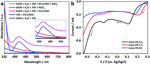
The block copolymer, PS-b-PEO, consists of two segments, i.e. polystyrene and poly(ethylene oxide), which have hydrophobic and hydrophilic behaviors, respectively. PS-b-PEO can be easily dissolved in THF to become a free unimer. The addition of an ethanol–water mixture induces the transformation of the free unimer into micelles, as indicated by the presence of the Tyndall scattering (Fig. S1, ESI†). The PS and PEO blocks act as the hydrophobic (core) and hydrophilic (shell) moieties of the micelles, respectively.25 The TEM images presented in Fig. S2 (ESI†) show that spherical micelles with average diameters of 15.5, 28.8, and 33.6 nm are formed from block copolymers PS(5000)-b-PEO(2200), PS(18000)-b-PEO(7500), and PS(63000)-b-PEO(26000), respectively.Previously, it was suggested that the incorporation of metal precursors into the micellar solution would not destroy the structure of the micelles.24 The metal precursor would be transformed into water-coordinated metal ion complexes in the micellar solution. UV-vis spectroscopy was employed to observe the interactions between water-coordinated metal ion complexes with the shells of the micelles (Fig. 1a). Initially, a UV-vis spectrum was recorded from the PdCl2 aqueous solution. The absorption peak centered at around 425 nm with a tail on the low energy side is assigned to the d–d transition in the Pd(II) complexes (inset in Fig. 1a). The spectrum indicates the presence of [PdCl4−x(H2O)x](−2+x) (where x varies from 0 to 4) complex species formed by the ligand exchange reaction between coordinated Cl− ions and water molecules in aqueous media.26,27 The charge on the complexes, accordingly, changes from 2− to 2+ with the increase in the number of water molecules (from 0 to 4) entering the coordination sphere of Pd2+ ions.28 The hyperchromic effect is observed in the UV-vis spectrum of the solution containing micelles and PdCl2. The spectrum is shifted upward without any position changes in the absorption peaks (Fig. 1a). The observed hyperchromic effect can be attributed to the existence of interactions between water-coordinated Pd ions and the shells of the micelles. Such interactions have been thought to occur through hydrogen bonding.29
In this work, mesoporous Pd films with different pore sizes were obtained by applying a deposition potential to conductive substrates (working electrodes), as shown in Scheme 1. The deposition potential applied to the Pd films was determined by carefully carrying out negative scan linear sweep voltammetry (LSV) at a slow scan rate from electrolyte solutions containing polymers with different molecular weights (Fig. 1b). The LSV curves confirm the reduction potential of Pd(II) into Pd(0). The plateau region of these LSV plots is observed at around 0.0 V (vs. Ag/AgCl), and hence, this potential was selected as the applied potential for the deposition of mesoporous Pd films. Previously, it was suggested that at a higher applied deposition potential (more positive), the reduction rate of metal ions became slower, which repelled the micelles.30 In contrast, at a lower applied deposition potential (more negative), the reduction rate became faster, which broke down the structure of the micelles.24,31
As discussed earlier, the water-coordinated metal ion complexes are thought to interact with the shells of the micelles through hydrogen bonding. The formation mechanism of the mesoporous Pd films can be described as follows. When an electrical current generated using a potentiostat (using the amperometric i–t technique) is passed through the working electrode, it attracts the metal ion complexes and the micelles to the working electrode. The charge of the metal ion complexes changes from −2 to +2, which is important for their assembly and interactions with the micelle domains. As a result, the negatively charged Cl−-rich metal complexes become attracted to the positively charged water-rich complexes through electrostatic interactions, thus increasing the amount of Pd(II) species in and around the micelles during the electrodeposition of Pd(0). The electrical current enables the reduction of Pd(II) ions to the Pd(0) metal. The number of reduced Pd ions (the deposited Pd) is associated with the charge passing through the working electrode to the electrolyte solution. Subsequently, the Pd metal constructs the pore walls which envelop the micelles as the electrical current passes through the working electrode. The complete removal of the polymeric templates is performed by immersing the deposited films in THF and Pd metallic framework films with mesoporous structures are generated on the substrate (Scheme 1).
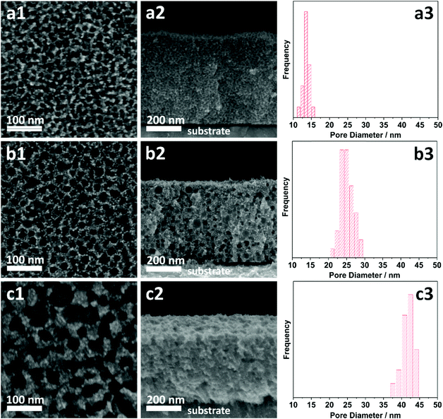
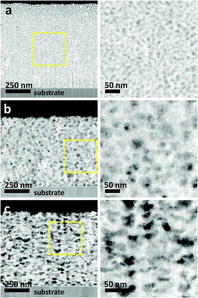
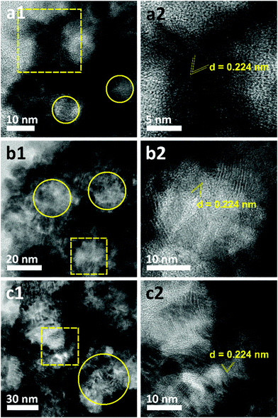
The morphologies of the as-prepared films were characterized by SEM (Fig. 2). Both top-view and cross-sectional observations reveal the continuous formation of spherical pores throughout the entire films arranged in a cage-type manner (Fig. 2a1–c1 and a2–c2). Moreover, from the top-view SEM images, the average pore sizes of meso Pd-2.2, meso Pd-7.5, and meso Pd-26 are measured to be 14, 25, and 41 nm, respectively, as statistically calculated from more than 100 pores (Fig. 2a3–c3). Furthermore, the contrast difference in the high-angle annular dark-field scanning TEM (HAADF-STEM) images indicates the porous nature of these films, in which the pores are constructed from the surface of the substrate to the top surface of the films, thereby suggesting the interconnected nature of the pore walls (Fig. 3). The high-resolution TEM (HR-TEM) images depicted in Fig. 4a1–c1 clearly reveal the existence of mesopores in each film, as indicated by the yellow circles. In contrast, no porous structure is observed in the Pd film deposited in the absence of polymeric micelles under similar electrodeposition conditions (Fig. S3, ESI†). This observation suggests that the spherical micelles present in the electrolyte solution play an important role in the formation of mesoporous Pd films.
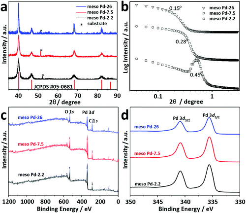
Thin film XRD was utilized to examine the crystal phase of these films (Fig. 5a). The diffraction patterns of the films with different pore sizes show diffraction peaks located at 40.18°, 46.72°, 68.16°, 82.18° and 86.82°, assigned to the (111), (200), (220), (311) and (222) diffraction planes of Pd with a face-centered cubic (fcc) structure, respectively (JCPDS Card No. 05-0681). Low-angle XRD is a useful technique for characterizing the d-spacing of well-ordered materials. For ordered mesoporous materials, the d-spacing which resulted from low-angle XRD measurements is commonly ascribed to the average distance between adjacent pores. Fig. 5b shows the low-angle XRD diffraction patterns recorded for meso Pd-2.2, meso Pd-7.5, and meso Pd-26. All the diffraction patterns exhibit peaks centered at 0.44°, 0.28°, and 0.15° for meso Pd-2.2, meso Pd-7.5, and meso Pd-26, respectively. The average pore-to-pore distances are estimated to be around 20.1, 31.6, and 58.9 nm for meso Pd-2.2, meso Pd-7.5, and meso Pd-26, respectively. These values are in good agreement with the average pore size and pore wall thickness estimated from the TEM and SEM images, respectively.
The crystallite sizes of meso Pd-2.2, meso Pd-7.5, and meso Pd-26 are estimated using the Scherrer equation to be 5.78, 5.99, and 6.29 nm, respectively, which roughly match the values estimated from the TEM images. The lattice spacing of the three-representative mesoporous Pd films were observed by HR-TEM, as depicted in Fig. 4a2–c2. Typical lattice fringes with a constant d-spacing of 0.224 nm, corresponding to the (111) lattice plane of the fcc Pd crystal, are observed, which is in good agreement with the XRD observation (Fig. 5a). Fig. 5c displays the XPS survey spectra recorded for the meso Pd-2.2, meso Pd-7.5, and meso Pd-26 films. The high-resolution Pd 3d spectrum clearly shows the presence of a doublet with peaks at 336 eV and 341 eV, indexed to metallic Pd 3d5/2 and Pd 3d3/2, respectively (Fig. 5d). However, the absence of the PdO peak in these films indicates that they are composed of pure metallic Pd.
Based on the estimated average pore-to-pore distance and the pore wall thickness, we modeled the pore arrangement in 1![[thin space (1/6-em)]](https://www.rsc.org/images/entities/char_2009.gif) 000
000![[thin space (1/6-em)]](https://www.rsc.org/images/entities/char_2009.gif) 000 nm3 (100 nm × 100 nm × 100 nm) and further estimated the surface area ratio of the pore/void region for the mesoporous films with three different pore sizes (Fig. S4, ESI†). By assuming that the volumetric dimensions of the deposited layer among the three films are identical, the ratio of the Pd surface areas of meso Pd-2.2, meso Pd-7.5, and meso Pd-26 is approximated to be 4
000 nm3 (100 nm × 100 nm × 100 nm) and further estimated the surface area ratio of the pore/void region for the mesoporous films with three different pore sizes (Fig. S4, ESI†). By assuming that the volumetric dimensions of the deposited layer among the three films are identical, the ratio of the Pd surface areas of meso Pd-2.2, meso Pd-7.5, and meso Pd-26 is approximated to be 4![[thin space (1/6-em)]](https://www.rsc.org/images/entities/char_2009.gif) :
:![[thin space (1/6-em)]](https://www.rsc.org/images/entities/char_2009.gif) 3
3![[thin space (1/6-em)]](https://www.rsc.org/images/entities/char_2009.gif) :
:![[thin space (1/6-em)]](https://www.rsc.org/images/entities/char_2009.gif) 2.
2.
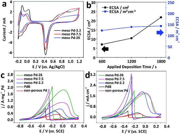
An electrochemical approach was employed to estimate the electrochemical active surface area (ECSA) of each mesoporous Pd film by carrying out cyclic voltammetry (CV) in 0.5 M H2SO4 electrolyte from −0.2 to +1.2 V (vs. Ag/AgCl) at a scan rate of 50 mV s−1 (Fig. 6a). The CV curves show the typical hydrogen and oxygen adsorption/desorption features. The ECSA was estimated by calculating the oxide reduction charge assuming that the conversion factor for an oxide monolayer reduction was 420 μC cm−2 on the surface of Pd.32 The ECSA values are 41.49, 32.27, and 21.75 cm2 for the meso Pd-2.2, meso Pd-7.5, and meso Pd-26 films with the very similar film thickness (∼500 nm), respectively, and these values closely match the surface area ratio of the films with three different average pore sizes estimated from the model (Fig. S4, ESI†). Clearly, meso Pd-2.2 has the largest ECSA since its pore size is relatively smaller than those of meso Pd-7.5 and meso Pd-26, implying that larger mesopores lead to smaller ECSA. When the ECSA is normalized with the respective deposited Pd mass, the mass-normalized ECSA for meso Pd-26 is larger (90.61 m2 g−1) than those of meso Pd-2.2 (40.28 m2 g−1) and meso Pd-7.5 (33.92 m2 g−1). Furthermore, the mass-normalized ECSA values of the mesoporous Pd films are obviously higher than those of the non-porous Pd film (11.38 m2 g−1) and commercially available Pd black, abbreviated as PdB (14.52 m2 g−1). The ECSA of meso Pd-26 linearly increases with the increase of film thickness (Fig. 6b, black line). Even when the ECSA values of the meso Pd-26 films with various thicknesses are divided by their respective geometric volumes, the volume-normalized ECSA values are relatively similar (Fig. 6b, blue line), suggesting that the large surface area derived from the mesoporous structure is fully accessible.
Electrooxidation of small organic molecules by noble metal catalysts is an important reaction in electrochemical energy conversion devices, such as direct alcohol fuel cells.33 The anodes on such devices typically require highly active and stable catalysts to ensure their good performance and durability to poisoning reaction intermediate products, such as carbon monoxide (CO), as well as deformation of the surface morphology.34 In this work, we carried out electrocatalytic tests of the meso Pd-2.2, meso Pd-7.5, and meso Pd-26 films toward the ethanol oxidation reaction (EOR) as the model reaction. For performance comparison, the non-porous Pd film and commercial PdB were also tested for the electrocatalytic EOR. The CV curves were recorded in 1.0 M KOH containing 1.0 M C2H5OH at a scan rate of 50 mV s−1 in the potential window of −0.8 V to +0.3 V (vs. SCE). All the mass-normalized CV curves clearly show the characteristics of the EOR in the forward and backward scans (Fig. 6c). The peak current density (mass-activity) of the meso Pd-26 film in positive sweep (1.82 A mg−1_Pd) is larger than those of the non-porous Pd film (0.32 A mg−1_Pd), PdB (0.52 A mg−1_Pd), and other mesoporous Pd films (meso Pd-2.2 and meso Pd-7.5). In addition, the ECSA-normalized CV curves show that the mesoporous Pd films show very high specific activity, compared to the non-porous Pd film and PdB. In spite of the different average pore sizes, the specific activities for all the mesoporous Pd films are almost similar (Fig. 6d). This implies that the stepped and kinked atomic arrangements of the mesoporous structures can significantly enhance the electrocatalytic activity of the catalyst.35
These results suggest that the large and open pores exhibited by the meso Pd-26 film are beneficial for providing better mass transport for the reactants and products from and to the electrolyte. To prove this, we have carried out additional CV measurements at various scan rates (Fig. S5a–c, ESI†). The diffusion efficiency of guest molecule species inside the mesopores can be determined by plotting the forward oxidation peak current densities versus the square root of the scan rates obtained from the CVs of the mesoporous Pd films with the three different average pore sizes.36 The slope value for the meso Pd-26 film is larger than those for the meso Pd-2.2 and meso Pd-7.5 films (Fig. S5d, ESI†), indicating that the diffusivity of ethanol molecules inside larger mesopores is higher than that inside smaller mesopores.37 To assess their stability, a chronoamperometry test was carried out in 1 M KOH containing 1.0 M C2H5OH at a constant potential of −0.1 V (vs. SCE) for 1500 s (Fig. S6a, ESI†). The current density of meso Pd-26 remains higher than those of the non-porous Pd film and PdB even after a long run of the stability test. The superior stability of meso Pd-26 can be attributed to its mesoporous architectures, which are beneficial for preventing aggregation or morphological deformation (Fig. S6b and c, ESI†).38
Conclusions
In summary, this study has demonstrated the facile preparation of continuous mesoporous Pd films with tunable pore size by polymeric micelle assembly through electrochemical deposition. The micelles play a critical role in the formation of the mesoporous structure and the size of the micelles is highly dependent on the molecular weight of the block copolymer, which also determines the pore size of the obtained mesoporous Pd films. The large open pores and mesoporous architectures of the as-prepared Pd films result in significantly better electrocatalytic activity and stability for the ethanol oxidation reaction compared to a non-porous Pd film and commercial PdB. The proposed approach can be extended to synthesize a wide range of mesoporous metallic films for various electrocatalytic applications.Author contributions
The manuscript was written through contributions of all authors. All authors have given approval to the final version of the manuscript.Conflicts of interest
There are no conflicts to declare.Acknowledgements
This work was supported by an Australian Research Council (ARC) Future Fellowship (grant FT150100479) and the research fund from the Suzuken Memorial Foundation. This work was performed in part at the Queensland Node of the Australian National Fabrication Facility, a company established under the National Collaborative Research Infrastructure Strategy to provide nano- and micro-fabrication facilities for Australia's researchers. M. I. would like to thank the Indonesia Endowment Fund for Education (LPDP) for the financial support.References
- J. Tao, J. Xiong, C. Jiao, D. Zhang, H. Lin and Y. Chen, ACS Sustainable Chem. Eng., 2016, 4, 60 CrossRef CAS.
- M. Manzano and M. Vallet-Regi, J. Mater. Chem., 2010, 20, 5593 RSC.
- Y. Li, N. Li, W. Pan, Z. Yu, L. Yang and B. Tang, ACS Appl. Mater. Interfaces, 2017, 9, 2123 CrossRef CAS PubMed.
- C. Perego and R. Milini, Chem. Soc. Rev., 2013, 42, 3956 RSC.
- J. Wei, Z. Sun, W. Luo, Y. Li, A. A. Elzatahry, A. M. Al-Enizi, Y. Deng and D. Zhao, J. Am. Chem. Soc., 2017, 139, 1706 CrossRef CAS PubMed.
- G. S. Attard, P. N. Bartlett, N. R. B. Coleman, J. M. Elliott, J. R. Owen and J. H. Wang, Science, 1997, 278, 838 CrossRef CAS.
- Y. Yamauchi and K. Kuroda, Chem. – Asian J., 2008, 3, 664 CrossRef CAS PubMed.
- A. Walcarius, E. Sibottier, M. Etienne and J. Ghanbaja, Nat. Mater., 2007, 6, 602 CrossRef CAS PubMed.
- Y. Yamauchi, A. Sugiyama, R. Ryoichi Morimoto, A. Takai and K. Kuroda, Angew. Chem., Int. Ed., 2008, 47, 5371 CrossRef CAS PubMed.
- C. Li, Ö. Dag, T. D. Dao, T. Nagao, Y. Sakamoto, T. Kimura, O. Terasaki and Y. Yamauchi, Nat. Commun., 2015, 6, 6608 CrossRef CAS PubMed.
- B. Jiang, C. Li, J. Tang, T. Takei, J. H. Kim, Y. Ide, J. Henzie, S. Tominaka and Y. Yamauchi, Angew. Chem., Int. Ed., 2016, 128, 10191 CrossRef.
- A. S. Nugraha, C. Li, B. Jiang, M. Iqbal, S. M. Alshehri, T. Ahamad, V. Malgras, Y. Yamauchi and T. Asahi, ChemElectroChem, 2017, 4, 2571 CrossRef CAS.
- D. Baba, C. Li, V. Malgras, B. Jiang, H. R. Alamri, Z. A. Alothman, M. S. A. Hossain, Y. Yamauchi and T. Asahi, Chem. – Asian J., 2017, 12, 2467 CrossRef CAS PubMed.
- C. Li, H. Tan, J. Lin, X. Luo, S. Wang, J. You, Y.-M. Kang, Y. Bando, Y. Yamauchi and J. Kim, Nano Today, 2018, 21, 91 CrossRef CAS.
- C. Li, M. Iqbal, J. Lin, X. Luo, B. Jiang, V. Malgras, K. C.-W. Wu, J. Kim and Y. Yamauchi, Acc. Chem. Res., 2018, 51, 1764 CrossRef CAS PubMed.
- E. Antolini, Energy Environ. Sci., 2009, 2, 915 RSC.
- E. Antolini, S. C. Zignani, S. F. Santos and E. R. Gonzalez, Electrochim. Acta, 2011, 56, 2299 CrossRef CAS.
- B. D. Adams and A. Chen, Mater. Today, 2011, 14, 282 CrossRef CAS.
- A. Chen and C. Ostrom, Chem. Rev., 2015, 115, 11999 CrossRef CAS PubMed.
- M. Armbrüster, M. Behrens, F. Cinquini, K. Föttinger, Y. Grin, A. Haghofer, B. Klötzer, A. Knop-Gericke, H. Lorenz, A. Ota, S. Penner, J. Prinz, C. Rameshan,, Z. Révay, D. Rosenthal, G. Rupprechter, P. Sautet, R. Schlögl, L. Shao, L. Szentmiklósi, D. Teschner, D. Torres, R. Wagner, R. Widmer and G. Wowsnick, ChemCatChem, 2012, 4, 1048 CrossRef.
- C. Li, T. Sato and Y. Yamauchi, Chem. Commun., 2014, 50, 11753 RSC.
- C. Li, B. Jiang, N. Miyamoto, J. H. Kim, V. Malgras and Y. Yamauchi, J. Am. Chem. Soc., 2015, 137, 11558 CrossRef CAS PubMed.
- L. Zhang, J. Zhang, Z. Jiang, S. Xie, M. Jin, X. Han, Q. Kuang, Z. Xie and L. Zheng, J. Mater. Chem., 2011, 21, 9620 RSC.
- M. Iqbal, C. Li, K. Wood, B. Jiang, T. Takei, Ö. Dag, D. Baba, A. S. Nugraha, T. Asahi, A. E. Whitten, M. S. A. Hossain, V. Malgras and Y. Yamauchi, Chem. Mater., 2017, 29, 6405 CrossRef CAS.
- K. Yu and A. Eisenberg, Macromolecules, 1998, 31, 3509 CrossRef CAS.
- L. I. Elding and L. F. Olsson, J. Phys. Chem., 1978, 82, 69 CrossRef CAS.
- R. J. Deeth and L. I. Elding, Inorg. Chem., 1996, 35, 5019 CrossRef CAS PubMed.
- K. Mech, P. Zabinski, R. Kowalik and K. Fitzner, J. Electrochem. Soc., 2013, 160, H770 CrossRef CAS.
- C. Albayrak, A. M. Soylu and Ö. Dag, Langmuir, 2008, 24, 10592 CrossRef CAS PubMed.
- G. S. Attard, J. M. Corker, C. G. Göltner, S. Henke and R. H. Templer, Angew. Chem., Int. Ed. Engl., 1997, 36, 1315 CrossRef CAS.
- J. M. Elliott, G. S. Attard, P. N. Bartlett, N. R. B. Coleman, D. A. S. Merckel and J. R. Owen, Chem. Mater., 1999, 11, 3602 CrossRef CAS.
- F. Kadirgan, B. Beden, J. M. Leger and C. Lamy, J. Electroanal. Chem., 1981, 125, 89 CrossRef CAS.
- B. Cai, S. Henning, J. Herranz, T. J. Schmidt and A. Eychmüller, Adv. Energy Mater., 2017, 7, 1700548 CrossRef.
- J. C. Meier, I. Katsounaros, C. Galeano, H. J. Bongard, A. A. Topalov, A. Kotska, A. Karschin, F. Schüth and K. J. J. Mayrhofer, Energy Environ. Sci., 2012, 5, 9319 RSC.
- L. P. Ford, P. Blowers and R. I. Masel, J. Vac. Sci. Technol., A, 1999, 17, 1705–1709 CrossRef CAS.
- Y. Noh, Y. Kim, S. Lee, E. J. Lim, J. G. Kim, M. S. Choi, M. H. Seo and W. B. Kim, Exploring the Effects of the Size of Reduced Graphene Oxide Nanosheets for Pt-Catalyzed Electrode Reactions, Nanoscale, 2015, 7, 9438–9442 CAS.
- D. Wen, A.-K. Herrmann, L. Borchardt, F. Simon, W. Liu, S. Kaskel and A. Eychmüller, J. Am. Chem. Soc., 2014, 136, 2727 CrossRef CAS PubMed.
- C. Zhu, D. Du, A. Eychmüller and Y. Lin, Chem. Rev., 2015, 115, 8896 CrossRef CAS PubMed.
Footnote |
| † Electronic supplementary information (ESI) available. See DOI: 10.1039/c8nh00507a |
| This journal is © The Royal Society of Chemistry 2019 |

