Boosting the electrochemical performance of carbon cloth negative electrodes by constructing hierarchically porous nitrogen-doped carbon nanofiber layers for all-solid-state asymmetric supercapacitors†
Ya-Nan
Liu
,
Jia-Nan
Zhang
,
Hai-Tao
Wang
,
Xiao-Hui
Kang
and
Shao-Wei
Bian
 *
*
Key Laboratory of Science and Technology of Eco-Textiles, Ministry of Education, College of Chemistry, Chemical Engineering and Biotechnology, Donghua University, Shanghai 201620, China. E-mail: bianshaowei@iccas.ac.cn; Tel: +86-21-67792049
First published on 10th August 2018
Abstract
The electrochemical performance of carbon cloth directly relates to its surface area and porosity, and the functional groups of the primary carbon fibers. In this study, after rationally functionalizing a carbon cloth fiber surface with 3D porous nitrogen-doped carbon nanofiber layers, the resultant 3D hierarchical porous nitrogen-doped carbon nanofibers/carbon cloth negative electrode exhibits superior supercapacitive performance due to its large surface area, suitable porosity, nitrogen-doped carbon surface and fast electron transportation. This electrode delivers high areal capacitance of 608 mF cm−2 at 1 mA cm−2 and good cycle life (capacitance retention of 99% after the 5000th cycle). An asymmetric supercapacitor device is also assembled by using NiO@carbon nanofibers/carbon cloth as the positive electrode and nitrogen-doped carbon nanofibers/carbon cloth as the negative electrode, which exhibits high energy density of 19.5 W h kg−1 at 4.1 kW kg−1.
Introduction
Driven by the growing demand for wearable electronics, considerable effort has been made to design a variety of high-performance flexible supercapacitors with the key characteristics including high energy density, excellent power density and good flexibility.1–3 Since the electrochemical performance of supercapacitors directly depends on their electrodes, rationally designing and constructing 3D hierarchical porous electrode structures are deemed as one of the most effective strategies to satisfy those requirements mentioned above.4 The accessible porosity and large electroactive surface area caused by the nanoscale effects can significantly increase the charge-storage capability of electrodes.5–7 This unique electrode structure is favourable to accommodate the electrode structure changes under various mechanical deformations.All sorts of electroactive materials including carbon materials, metal oxides, and conducting polymers, have been widely applied in flexible supercapacitor electrodes.4,8–10 Among them, carbon cloth (CC), woven from numerous uniform carbon microfibers, possesses remarkable properties including high conductivity, excellent flexibility, good chemical stability and high mechanical strength, which is a promising negative electrode material for constructing flexible supercapacitors.2,5,9,11 Nevertheless, their low specific surface area, poor porosity and hydrophobic fiber surface result in low capacitance (0.34 mF cm−2). Thus, directly using CC as a negative electrode inevitably degrades the electrochemical performance of flexible supercapacitors.5,12 A series of strategies have been proposed to address the above-mentioned issues.12–14 Wang et al., adopted a “soaking–recrystallization–calcination” method to enhance the capacitance performance of CC. The areal capacitance was increased to 362 mF cm−2.14 However, the direct surface activation of CC inevitably lowers the conductivity of the entire electrode and thus limits the eventual increase in capacitance. Meanwhile, this strategy often decays its mechanical strength. Recently, functionalizing the carbon microfiber surface with proper 3D hierarchical porous structure and desirable functional groups to boost the electrochemical performance has aroused widespread concern. Dryfe et al. developed a graphene oxide-assisted EPD method and a hydrogen thermal reduction process to prepare a reduced graphene-NTs/CC (G-CNT/CC) electrode with a specific capacitance of 150.1 F g−1.13 Unfortunately, the unsatisfactory electrochemical performance, and the lack of proper and general methodologies are the two major issues limiting this strategy to be further applied in CC-based negative electrode materials. Therefore, precisely functionalizing and tuning the CC microfiber surface with a 3D hierarchical porous structure still remains a huge challenge in supercapacitor electrodes.
In this study, a high-performance nitrogen-doped carbon nanofibers/carbon cloth (NCNFs/CC) negative electrode was designed and prepared by rationally functionalizing the carbon cloth fiber surface with 3D porous nitrogen-doped carbon nanofiber (NCNF) layers, which results in large specific surface area, suitable porosity, nitrogen-doped carbon surface and fast electron transportation, significantly enhancing the supercapacitive performance of CC. This electrode delivers high areal capacitance of 608 mF cm−2 at 1 mA cm−2 and good cycle life (capacitance retention of 99% after the 5000th cycle). A flexible all-solid-state asymmetric supercapacitor device is also assembled by using NiO@carbon nanofibers/carbon cloth (NiO@CNFs/CC) as the positive electrode and NCNFs/CC as the negative electrode. It exhibits an energy density of 19.5 W h kg−1 at 4.1 kW kg−1.
Experimental procedures
Synthesis of 3D porous nitrogen-doped carbon nanofibers/carbon cloth as a negative electrode material
All of the chemical regents were of analytical grade and used without further purification. The CC was first cleaned ultrasonically in acetone, ethanol and deionized (DI) water for 10 min, respectively, then dried at 50 °C in a vacuum oven overnight. The porous carbon nanofiber (CNF) layers grew on the surface of the carbon fiber cores inside the CC via a chemical vapor deposition (CVD) method according to our previous work.4In order to form NCNF layers on the surface of the carbon microfiber cores, the obtained carbon nanofibers/carbon cloth (CNFs/CC) was first immersed in 50 ml of aqueous solution containing 0.14 g of 3-hydroxytyramine hydrochloride. After adjusting the pH value to around 9, it was stirred for 10 h at room temperature. Then the sample was dried at 50 °C overnight in a vacuum oven. Finally, the sample was placed in a tube furnace at 500 °C for 2 h to form NCNFs/CC. The mass loading of NCNFs on CC is around 3.2 mg cm−2.
Synthesis of NiO@carbon nanofibers/carbon cloth as a positive electrode material
A chemical bath deposition (CBD) process was applied to grow Ni(OH)2 nanosheet layers on the surface of the CNFs inside the CNFs/CC at room temperature.15 A piece of CNFs/CC was first immersed into 40 ml of an aqueous solution containing 1 ml of ammonia, 1.05 g of Ni(NO3)2·6H2O and 0.20 g of potassium persulfate. After stirring for 60 s, Ni(OH)2@CNFs/CC was collected, washed with DI water and dried at 50 °C in a vacuum oven overnight. Finally, it was calcined at 300 °C in a tube furnace for 2 h to form the NiO@CNFs/CC electrode material. The mass loading of NiO is around 1.2 mg cm−2.Characterization
The microstructure of the electrodes was characterized using a scanning electron microscope (SEM, Hitachi S-4800) and a transmission electron microscope (TEM, JEOL JEM-2100F). X-Ray powder diffraction (XRD) patterns were collected on a Rigaku D/MAX-2550PC X-Ray diffractometer with Cu Kα radiation. The NiO mass loading was determined using an inductively coupled plasma optical emission spectrometer (Prodigy ICP-OES). The pore properties were investigated on a JWGB-JK122W sorption analyzer at liquid N2 temperature (77 K). X-ray photoelectron spectroscopy (XPS) characterization was conducted using a Thermo Scientific ESCALAB 250Xi instrument.Fabrication of all-solid-state asymmetric supercapacitor devices
The PVA-KOH gel electrolyte was prepared as follows. 20 ml of DI water containing 3 g of PVA was heated at 85 °C under stirring until a clear solution was observed. Then 10 ml of DI water containing 3.36 g of KOH was added dropwise into the above solution under stirring at room temperature until the solution became clear.A flexible all-solid-state asymmetric supercapacitor (ASC) device was assembled by using NCNFs/CC and NiO@CNFs/CC as the negative and positive electrodes, respectively. The NCNFs/CC and NiO@CNFs/CC electrodes were first immersed into the PVA-KOH gel electrolyte and then were sandwiched, with filter paper as the separator. Finally, the assembled ASC device was dried for 20 h at room temperature.
Electrochemical measurements
The cyclic voltammetry (CV) and galvanostatic charge–discharge (GCD) measurements were performed in a three-electrode system using a CHI 660E electrochemical workstation (CHI, Shanghai, China). Aqueous KOH solution with a concentration of 2 mol L−1 was used as the electrolyte. The NCNFs/CC or NiO@CFs/CC electrodes (1 × 1.3 cm2) were directly used as the working electrode. The reference and counter electrodes were a saturated calomel electrode and platinum wire, respectively. The electrochemical performance of the all-solid-state asymmetric supercapacitor device was evaluated in a two-electrode system.The specific capacitance, energy density (E) and power density (P) were calculated according to eqn (1)–(4):10,16–18
 | (1) |
 | (2) |
 | (3) |
 | (4) |
Results and discussion
Our strategy to form 3D porous NCNF layers on the surface of carbon microfiber cores is depicted in Scheme 1. 3D hierarchical porous NCNF layers were constructed on the carbon microfiber surface inside CC through combining the CVD growth of 3D hierarchical porous CNF layers and the carbonization of nitrogen containing precursor, polydopamine (PDA) shells, on the CNF surface. The 3D porous NCNF layers with large surface area, suitable pore structure, short ion diffusion path and fast electron transportation rate are highly desirable for the electric double-layer capacitance (EDLC).19,20 Meanwhile, in the nitrogen-doped carbon structure, a pair of electrons offered by the nitrogen heteroatoms can significantly change the electron donor–acceptor characteristics of carbon materials, which can further enhance the conductivity of carbon materials, introduce pseudocapacitance and improve the wettability of the carbon surface for electrolyte accessibility.21,22 When used as a flexible binder-free supercapacitor negative electrode, the NCNFs/CC electrode exhibited good electrochemical performance.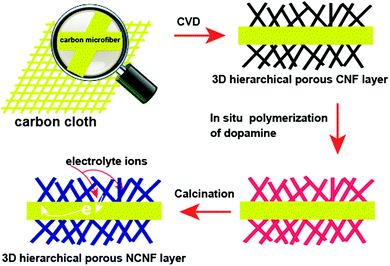 | ||
| Scheme 1 Schematic illustration of the preparation process of the flexible 3D NCNFs/CC negative electrode material. | ||
The ordered woven structure of CC is shown in Fig. 1a. It is constructed by lots of uniform carbon microfibers with an average diameter of 12 μm. Fig. 1b and c shows that these carbon microfibers have a smooth surface and solid nature. After the CVD growth of CNFs on the surface of the carbon microfiber cores, the intertwined CNFs formed a 3D hierarchically porous layer (Fig. 1d–f and the inset in Fig. 1f). The hydrophobic property of carbon materials often leads to low wettability of the porous carbon skeleton and thus decreases the diffusion efficiency of electrolyte ions. Nitrogen-doping of the surface of CNFs can improve the wettability of the carbon surface for electrolyte accessibility, leading to an enhanced electrochemical performance.23–26Fig. 1g–i shows that PDA@CNFs/CC maintained the 3D porous structure after in situ polymerizing dopamine on the surface of the CNFs. NCNFs/CC retains the original structure of CC after a high-temperature calcination treatment in a nitrogen flow, demonstrating its high thermal stability (Fig. 1j). The abundant pores inside the NCNFs layers were well preserved (Fig. 1k–m), which facilitates the diffusion of electrolyte ions. TEM images in Fig. 1n further reveal the 3D hierarchical porous structure inside the layers of NCNFs, which is consistent with the SEM characterization result. The average diameter of curved NCNFs is 25 nm. High-resolution TEM images (Fig. 1o and its inset) display the lattice fringe, indicating the good graphitization degree of NCNFs.
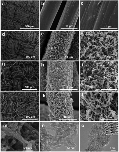 | ||
| Fig. 1 SEM images of (a–c) CC, (d–f) CNFs/CC, (g–h) PDA@CNFs/CC and (j–m) NCNFs/CC. (n and o) TEM images of NCNFs/CC. The inset in (o) is the high-resolution TEM image of NCNFs/CC. | ||
XPS measurements were conducted to analyze the components and chemical bonding at the surface of NCNFs/CC. Three strong peaks in the XPS survey spectrum confirm the existence of C, N and O elements in NCNFs/CC (Fig. 2a). No trace of impurities was observed. The atom percentage of N is 9.4%. The high-resolution C 1s spectrum can be mainly deconvoluted into three peaks at around 284.4 eV, 285.2 eV and 286.6 eV, corresponding to C![[double bond, length as m-dash]](https://www.rsc.org/images/entities/char_e001.gif) C, C–N and C–O, respectively (Fig. 2b).6 The deconvolution of the high-resolution N 1s spectrum of NCNFs results in three peaks, which are correlated to different electronic states of nitrogen functional groups: pyridinic-N (N-6, 398.8 eV), pyrrolic/pyridine groups (N-5, 400.4 eV), and quaternary nitrogen (N-Q, 401.4 eV) (Fig. 2c).6,22,27 Among them, N-5 and N-6 bring additional pseudocapacitance, and N-Q can improve the electrode conductivity.11 The presence of nitrogen atoms in carbon-based materials will not only improve the carbon affinity to electrolyte ions, but may also contribute additional pseudocapacitance to the total capacitance.28 The structure changes of CC caused by the nitrogen-doping process were further investigated by Raman analysis (Fig. 2d). Two peaks are located at around 1360 cm−1 and 1591 cm−1, which relate to the D and G bands of the carbon structure.29 The intensity ratios of the D/G band (ID/IG) were estimated to be 1.10 and 0.78 for CC and CNFs/CC, respectively. The decrease in the D/G band intensity ratio indicates less defects present in CNFs/CC and a higher degree of graphitization after the CVD growth process of CNFs on the carbon microfibers. NCNFs/CC has a slightly higher D/G band intensity ratio (0.82) than CNFs/CC, indicating the formation of amorphous nitrogen-doped layers on the surface of the CNFs.
C, C–N and C–O, respectively (Fig. 2b).6 The deconvolution of the high-resolution N 1s spectrum of NCNFs results in three peaks, which are correlated to different electronic states of nitrogen functional groups: pyridinic-N (N-6, 398.8 eV), pyrrolic/pyridine groups (N-5, 400.4 eV), and quaternary nitrogen (N-Q, 401.4 eV) (Fig. 2c).6,22,27 Among them, N-5 and N-6 bring additional pseudocapacitance, and N-Q can improve the electrode conductivity.11 The presence of nitrogen atoms in carbon-based materials will not only improve the carbon affinity to electrolyte ions, but may also contribute additional pseudocapacitance to the total capacitance.28 The structure changes of CC caused by the nitrogen-doping process were further investigated by Raman analysis (Fig. 2d). Two peaks are located at around 1360 cm−1 and 1591 cm−1, which relate to the D and G bands of the carbon structure.29 The intensity ratios of the D/G band (ID/IG) were estimated to be 1.10 and 0.78 for CC and CNFs/CC, respectively. The decrease in the D/G band intensity ratio indicates less defects present in CNFs/CC and a higher degree of graphitization after the CVD growth process of CNFs on the carbon microfibers. NCNFs/CC has a slightly higher D/G band intensity ratio (0.82) than CNFs/CC, indicating the formation of amorphous nitrogen-doped layers on the surface of the CNFs.
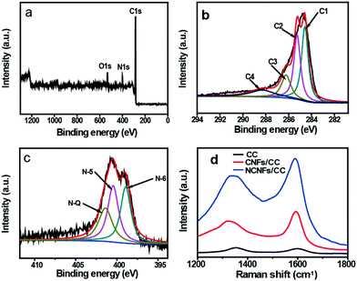 | ||
| Fig. 2 XPS spectra of NCFs/CC: (a) survey spectrum, (b) high-resolution C 1s spectrum and (c) high-resolution N 1s spectrum. (d) Raman spectra of CC, CNFs/CC and NCNFs/CC. | ||
The porosity properties of CC, CNFs/CC and NCNFs/CC were characterized by nitrogen adsorption analysis. The nitrogen adsorption–desorption isotherms of CNFs/CC and NCNFs/CC are shown in Fig. 3a. The hysteresis loops were clearly observed in the relative pressure (P/P0) range of 0.5–1.0. The BET specific surface area of NCNFs/CC and CNFs/CC were calculated to be 88.4 m2 g−1 and 82.6 m2 g−1, respectively, which are higher than pure CC (27 m2 g−1). Fig. 3b reveals that CNFs/CC and NCNFs/CC have a hierarchical porous structure caused by the porous carbon layers (CNFs and NCNFs) and spaces between the carbon microfibers inside CC. The BJH average pore size for CNFs/CC and NCNFs were determined to be 11.9 nm and 20.3 nm, respectively. Based on the nitrogen adsorption analysis results, the nitrogen-doping process could increase both the BET specific surface area and pore size of CNFs/CC, facilitating provision of a large interface between the carbon materials and electrolyte, and enabling the possibility of rapid diffusion of the electrolyte ions inside the electrodes.
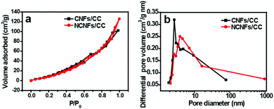 | ||
| Fig. 3 (a) N2 adsorption–desorption isotherms and (b) BJH pore size distribution of CNFs/CC and NCNFs/CC. | ||
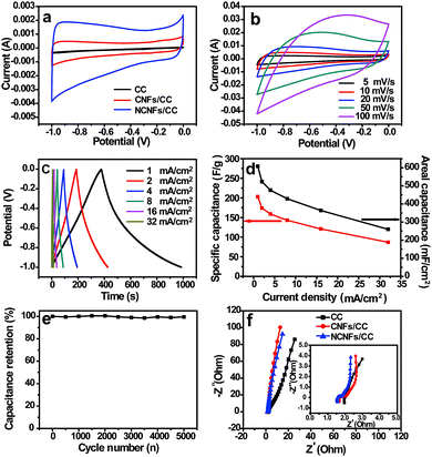
Due to the abundant pores mainly generated from the NCNFs layers, conductive carbon network, high specific surface area and nitrogen-doping feature, NCNFs/CC was tested as a flexible supercapacitor electrode. The typical CV curves of CC, CNFs/CC and NCNFs/CC were compared within a potential window of −1 to 0 V at the same scan rate of 5 mV s−1 to understand the effect of electrode structure on the electrochemical performance (Fig. 4a). The typical CV curves of NCNFs/CC displayed the characteristic quasi-rectangular shape for the double-layer capacitor. The enhanced CV curve area of NCNFs/CC is several times larger than that of CC and CNFs/CC, indicating that the capacitance was substantially enhanced due to the NCNFs layers with high specific surface area, appropriate porosity and high wettability. The CV curves of NCNFs/CC at various scan rates ranging from 5 to 100 mV s−1 are presented in Fig. 4b, which maintained a similar shape even at high scan rate up to 100 mV s−1, indicating the excellent electrochemical performance. At different current densities, the GCD curves displayed symmetrical and linear shapes (Fig. 4c). Notably, no obvious IR drop was seen in the GCD curves. The superior double-layer capacitive behavior mainly relates to the good conductivity and fast electrolyte ion diffusion. As shown in Fig. 4d, the areal capacitances gradually decreased with current density. The maximum areal capacitance was calculated to be 608 mF cm−2 (203 F g−1) at a current density of 1 mA cm−2, which is superior to the recently reported carbon cloth-based EDLC materials, such as CFC-750-N-S (362 mF cm−2), activated CC (88 mF cm−2), CNT-grafted ACC (117 F g−1) and ACC (125–135 F g−1).5,30–33
Long-term stability facilitates the practical application of supercapacitor electrodes. The electrode retained 99% of its initial capacitance after the 5000th cycle at a current density of 60 mA cm−2 (Fig. 4e). No obvious capacitance decay and electrode structure change were observed. This long-term cycling performance proves the remarkable electrochemical stability of NCNFs/CC. The impedance spectrum is shown as the Nyquist plot in Fig. 4f. CC, CNFs/CC and NCNFs/CC exhibited a similar EIS shape, which is composed of a semicircle in the high frequency region and a sloped line in the low frequency region. Compared to CC, the more vertical lines of CNFs/CC and NCNFs/CC with a larger slope suggest better capacitive behavior and smaller diffusion resistance. The x-intercept of the semicircle represents the bulk solution resistance (Rs), and the diameter of the semicircle corresponds to the charge-transfer resistance (Rct). The Nyquist plots can be well fitted by the equivalent circuit model (the inset in Fig. 4f). It is observed that both the Rs (0.46 Ω) and Rct (0.21 Ω) of NCNFs/CC are smaller than that of CS (i.e., 0.57 Ω and 0.33 Ω, respectively), suggesting a lower internal resistance desirable for the high-rate delivery.23
In order to investigate the influence of various mechanical deformations on the electrochemical performance, the CV curves and their corresponding capacitance retentions under bending and twisting conditions were recorded. No obvious changes were observed in the CV curves and capacitance retentions when NCNFs/CC was bended to different angles (Fig. 5a and b). NCNFs/CC exhibited stable electrochemical performance during 120 bending cycles, retaining 96% of its initial capacitance (Fig. 5c and d). As shown in Fig. 5e and f, the electrode exhibited almost the same CV curves during 120 twisting cycles. The loss of capacitance is only 3% at the 120th twisting cycle. The performance durability of NCNFs/CC indicates the strong interface between the CC electrode substrate and the 3D porous NCNFs layers, which favours accommodating the structure change during various mechanical deformations. This unique property provides it with a bright future in flexible energy storage devices.
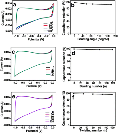 | ||
| Fig. 5 CV curves and capacitance retentions of NCNFs/CC at different (a and b) bending angles, (c and d) bending cycles and (e and f) twisting cycles. | ||
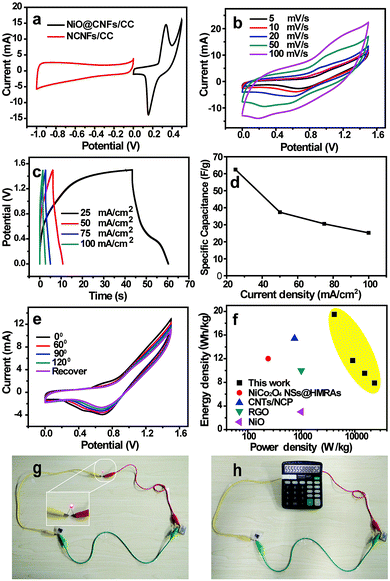
Assembling an asymmetric supercapacitor can effectively increase the potential window, resulting in an enhanced energy density. Based on the charge balance of positive and negative electrodes, NiO@CNFs/CC was synthesized as the positive electrode through a combined chemical bath deposition and calcination process (Fig. S1 and S2, ESI†), which shows a high areal capacitance of 1045 mF cm−2 and good flexibility (Fig. S3, ESI†). Fig. 6a shows the typical CV curves of NCNFs/CC and NiO@CNFs/CC electrodes at 5 mV s−1, which demonstrate that the stable voltage window for the ASC device can be broadened to 0–1.5 V. The CV curves of the ASC device at different scan rates displayed a similar CV curve shape (Fig. 6b), indicating a good capacitance performance. Fig. 6c and d present the GCD curves and their corresponding specific capacitances of the ASC device at different current densities, respectively. The largest specific capacitance is 62.4 F g−1 at a current density of 20 mA cm−2. At different bending angles, the similar CV curves indicate that the bending of the device exerts negligible influence over the capacitive behavior due to the good flexibility and robust electrode structure (Fig. 6e). The Ragone plots in Fig. 6f show that the assembled ACS device exhibited a high energy density of 19.5 W h kg−1 at a power density of 4.1 kW kg−1, which is superior to the recently reported ASC devices based on NiCo2O4 NSs@HMRAs (15.42 W h kg−1), CNTs/NCP (12.0 W h kg−1), RGO (3 W h kg−1) and NiO (10 W h kg−1).34–37
The assembled ASC device was also tested to evaluate its potential in powering small electronic devices, such as a red light-emitting diode (LED) and calculator. Two ASC devices were first connected in series. Then they were charged for 10 s using a commercial 9 V battery. The LED was successfully lighted up (Fig. 6g). A calculator powered by this assembled ASC devices in series can also be operated (Fig. 6h). Based on these above results, the ASC devices have potential in wearable electronics.
Conclusion
In summary, a 3D hierarchical porous NCNFs/CC negative electrode material with remarkable characterics including large surface area, accessible porosity and proper functional groups has been fabricated through combining a CVD growth of CNFs and a nitrogen-doping process. The obtained NCNFs/CC exhibited high areal capacitance of 608 mF cm−2, good cycling stability of 99% of its initial capacitance after 5000 cycles and stable electrochemical performance under various mechanical deformations. Using NCNFs/CC and NiO@CNFs/CC as the negative and positive electrodes, respectively, the assembled ASC device reached a high energy density of 19.5 W h kg−1 at a power density of 4.1 kW kg−1. These excellent performances can be mainly ascribed to the synergistic combination of large surface area and proper porosity with surface electrochemically active functional groups.Conflicts of interest
There are no conflicts to declare.Acknowledgements
This work was supported by the National Natural Science Foundation of China (51402048), the Fundamental Research Funds for the Central Universities, DHU Distinguished Young Professor Program and the Scientific Research Foundation for the Returned Overseas Chinese Scholars, State Education Ministry.References
- M. X. Guo, S. W. Bian, F. Shao, S. Liu and Y. H. Peng, Electrochim. Acta, 2016, 209, 486–497 CrossRef CAS.
- J. N. Zhang, P. Liu, L. N. Jin, C. Jin and S. W. Bian, ChemistrySelect, 2017, 2, 8618–8624 CrossRef CAS.
- H. Yin, X.-X. Yu, Y.-W. Yu, M.-L. Cao, H. Zhao, C. Li and M.-Q. Zhu, Electrochim. Acta, 2018, 282, 870–876 CrossRef CAS.
- J.-N. Zhang, P. Liu, C. Jin, L.-N. Jin, S.-W. Bian, Q. Zhu and B. Wang, Electrochim. Acta, 2017, 256, 90–99 CrossRef CAS.
- G. Wang, H. Wang, X. Lu, Y. Ling, M. Yu, T. Zhai, Y. Tong and Y. Li, Adv. Mater., 2014, 26, 2676–2682 CrossRef CAS.
- J.-G. Wang, H. Liu, H. Sun, W. Hua, H. Wang, X. Liu and B. Wei, Carbon, 2018, 127, 85–92 CrossRef CAS.
- H. Yin, M.-L. Cao, X.-X. Yu, H. Zhao, Y. Shen, C. Li and M.-Q. Zhu, Mater. Chem. Front., 2017, 1, 1615–1621 RSC.
- K. Zhu, Y. Wang, J. A. Tang, S. Guo, Z. Gao, Y. Wei, G. Chen and Y. Gao, Mater. Chem. Front., 2017, 1, 958–966 RSC.
- M. Cheng, Y. Meng, Q. Meng, L. Mao, M. Zhang, K. Amin, A. Ahmad, S. Wu and Z. Wei, Mater. Chem. Front., 2018, 2, 986–992 RSC.
- Y.-N. Liu, L.-N. Jin, H.-T. Wang, X.-H. Kang and S.-W. Bian, J. Colloid Interface Sci., 2018, 530, 29–36 CrossRef CAS.
- T. Qin, S. Peng, J. Hao, Y. Wen, Z. Wang, X. Wang, D. He, J. Zhang, J. Hou and G. Cao, Adv. Energy Mater., 2017, 7, 1700409 CrossRef.
- W. Wang, W. Liu, Y. Zeng, Y. Han, M. Yu, X. Lu and Y. Tong, Adv. Mater., 2015, 27, 3572–3578 CrossRef CAS.
- S. Wang and R. A. W. Dryfe, J. Mater. Chem. A, 2013, 1, 5279–5283 RSC.
- T. Ouyang, K. Cheng, F. Yang, J. Jiang, J. Yan, K. Zhu, K. Ye, G. Wang, L. Zhou and D. Cao, Chem. Eng. J., 2018, 335, 638–646 CrossRef CAS.
- Z. Tang, C.-h. Tang and H. Gong, Adv. Funct. Mater., 2012, 22, 1272–1278 CrossRef CAS.
- S. Gao, F. Liao, S. Ma, L. Zhu and M. Shao, J. Mater. Chem. A, 2015, 3, 16520–16527 RSC.
- W.-w. Liu, C. Lu, K. Liang and B. K. Tay, J. Mater. Chem. A, 2014, 2, 5100–5107 RSC.
- C. Jin, H.-T. Wang, Y.-N. Liu, X.-H. Kang, P. Liu, J.-N. Zhang, L.-N. Jin, S.-W. Bian and Q. Zhu, Electrochim. Acta, 2018, 270, 205–214 CrossRef CAS.
- J. Wu, P. Guo, R. Mi, X. Liu, H. Zhang, J. Mei, H. Liu, W.-M. Lau and L.-M. Liu, J. Mater. Chem. A, 2015, 3, 15331–15338 RSC.
- J. Wu, W.-W. Liu, Y.-X. Wu, T.-C. Wei, D. Geng, J. Mei, H. Liu, W.-M. Lau and L.-M. Liu, Electrochim. Acta, 2016, 203, 21–29 CrossRef CAS.
- X. Yu, J. Zhao, R. Lv, Q. Liang, C. Zhan, Y. Bai, Z.-H. Huang, W. Shen and F. Kang, J. Mater. Chem. A, 2015, 3, 18400–18405 RSC.
- J. Zhang, X. Zhang, Y. Zhou, S. Guo, K. Wang, Z. Liang and Q. Xu, ACS Sustainable Chem. Eng., 2014, 2, 1525–1533 CrossRef CAS.
- X. Lu, Y. Hu, L. Wang, Q. Guo, S. Chen, S. Chen, H. Hou and Y. Song, Electrochim. Acta, 2016, 189, 158–165 CrossRef CAS.
- A. Alabadi, X. Yang, Z. Dong, Z. Li and B. Tan, J. Mater. Chem. A, 2014, 2, 11697–11705 RSC.
- H. Wang, H. Yi, X. Chen and X. Wang, J. Mater. Chem. A, 2014, 2, 3223 RSC.
- F. Lai, Y. E. Miao, L. Zuo, H. Lu, Y. Huang and T. Liu, Small, 2016, 12, 3235–3244 CrossRef CAS.
- X. Wei, S. Wan and S. Gao, Nano Energy, 2016, 28, 206–215 CrossRef CAS.
- L. Li, R. Li, S. Gai, S. Ding, F. He, M. Zhang and P. Yang, Chem. – Eur. J., 2015, 21, 7119–7126 CrossRef CAS.
- Y.-C. Chang, Y.-C. Shih, J.-Y. Chen, G.-Y. Lin, N.-Y. Hsu, Y.-S. Chou and C.-H. Wang, RSC Adv., 2016, 6, 102068 RSC.
- J. Du, D. Mishra and J.-M. Ting, Appl. Surf. Sci., 2013, 285, 483–489 CrossRef CAS.
- Z. Li, Y. Li, L. Wang, L. Cao, X. Liu, Z. Chen, D. Pan and M. Wu, Electrochim. Acta, 2017, 235, 561–569 CrossRef CAS.
- T. Ouyang, K. Cheng, F. Yang, J. Jiang, J. Yan, K. Zhu, K. Ye, G. Wang, L. Zhou and D. Cao, Chem. Eng. J., 2018, 335, 638–646 CrossRef CAS.
- C. Kim, P. Srimuk, J. Lee, S. Fleischmann, M. Aslan and V. Presser, Carbon, 2017, 122, 329–335 CrossRef CAS.
- X.-F. Lu, D.-J. Wu, R.-Z. Li, Q. Li, S.-H. Ye, Y.-X. Tong and G.-R. Li, J. Mater. Chem. A, 2014, 2, 4706 RSC.
- J. Zhang, J. Jiang, H. Li and X. S. Zhao, Energy Environ. Sci., 2011, 4, 4009 RSC.
- X. Xu, M. Wang, Y. Liu, Y. Li, T. Lu and L. Pan, Energy Storage Mater., 2016, 5, 132–138 CrossRef.
- D.-W. Wang, F. Li and H.-M. Cheng, J. Power Sources, 2008, 185, 1563–1568 CrossRef CAS.
Footnote |
| † Electronic supplementary information (ESI) available: Additional figures and associated discussions. See DOI: 10.1039/c8qm00293b |
| This journal is © the Partner Organisations 2019 |

