Facile synthesis of intelligent nanocomposites as encapsulation for materials protection†
Peng
Du
 ab,
Juan
Wang
a,
Guangzhou
Liu
b,
Haichao
Zhao
 *a and
Liping
Wang
*a
aKey Laboratory of Marine Materials and Related Technologies, Zhejiang Key Laboratory of Marine Materials and Protective Technologies, Ningbo Institute of Materials Technology and Engineering, Chinese Academy of Sciences, Ningbo 315201, China. E-mail: zhaohaichao@nimte.ac.cn; wangliping@nimte.ac.cn
bInstitute of Marine Science and Technology, Shandong University, Qingdao 266200, China
First published on 21st December 2018
Abstract
Graphene grafted with polymers has exhibited a superior labyrinth effect. However, avoiding micro-galvanic corrosion is challenging if this material forms a conductive pathway with corrosive media. Although methods for preparing smart barrier-insulated graphene have been reported, the resulting synergistic flexibility and self-healing performance have yet to be studied. Herein, we have developed two strategies that use a layered double hydroxide to solidify poly(3,4-ethylenedioxythiophene) effectively. The synthesis and exfoliation of MgAl-LDH/PEDOT:PSS hybrid materials and their flocculation with reduced graphene oxide through charge-directed assembly are reported. The as-synthesized LDH/PEDOT:PSS@RGO hybrid materials showed lateral dimensions of hundreds to thousands of nanometres. Furthermore, the nanocomposites yielded a hybrid film through incorporation into polyvinylbutyral, with the coatings exhibiting significant corrosion resistance and avoiding micro-galvanic corrosion. These materials have a self-healing capability that responds to stimuli from the environment due to PEDOT:PSS undergoing ionic crosslinking. In brief, through simple synthesis, analysis of corrosion inhibition behaviour, and examination of interface adsorption, hybrid films with enhanced corrosion–resistance are reported as promising candidates for materials protection.
Introduction
Recently, graphene has received much interest in metallic protection owing to its unique properties, such as impermeability, chemical stability, and mechanical strength.1–3 However, the high aspect ratio and strong conductivity of graphene sheets limit their further applications.4 For instance, several studies have shown that polymer coatings with a graphene nanofiller accelerate metal corrosion in a long-term corrosive environment owing to the microgalvanic corrosion mechanism.5 Therefore, numerous interface treatments have been adopted.6 Previous studies have successfully inhibited this corrosion–promotion activity by covering the insulating materials.7,8 However, the “encapsulated graphene” only served as a physical barrier and became more inflexible in practical applications. Therefore, the single barrier property of two-dimensional materials (2DMs) is considered a bottleneck for material protection. Notably, fabricating flexibly conductive polymer/graphene is a promising method for obtaining well dispersed graphene pigment. Furthermore, modifying graphene with low conductive polymer loadings not only enhances the thermal and chemical stability,9 but also has a corrosion inhibitory effect. However, the corrosion or gas barrier system cannot effectively prevent corrosion when the conductive polymer and graphene were linked, because redox reactions were prone to occurring after the corrosive agents penetrated the metal surface.10To solve these problems, it is necessary to increase the flexibility and inhibit the corrosion–promotion activity.11 Heterocyclic conjugated macromolecule poly(3,4-ethylenedioxythiophene)-poly(styrenesulfonate) (PEDOT:PSS)12 has attracted significant attention owing to its superior absorptivity, quantum yields, polymer stability, and small molecular volume compared with conventional polymer nanofillers, such as polyaniline, polycarbonate, polypyrrole, and polythiophene.13,14 The modified molecules are tiny enough to avoid interconnections through and with graphene. Furthermore, layered double hydroxides (LDHs) are well-known layered nanomaterials known to avoid corrosion.15 The insulating LDH cover can remove the conductive polymer/graphene–metal couple by cutting off the connection between interface electricity and the aggressive electrolyte. LDHs are layered clay compounds with the general formula [M1−x2+Mx3+(OH)2]x+(An−)x/n·mH2O,16,17 and are used to extend the diffusion path of gas molecules.18 LDHs serve as appropriate holders for invasive chloride ions owing to their unique structures, which offer potent adsorption and anion-exchange abilities.19 Based on the components of LDH and the characteristics of PEDOT:PSS, we found that when the PEDOT:PSS coating was stimulated by the environment, bivalent ions (Mg2+) promoted ionic crosslinking of the polymer,20,21 endowing the composite film with a self-repairing capacity.
Herein, we present the synthesis and assembly of LDH with PEDOT:PSS using two methods, namely intercalation and hydrothermal treatment.22,23 These composite materials containing reduced graphene oxide (prepared graphene using a chemical method) were obtained using a simple route. The composite materials not only avoided galvanic corrosion owing to the covering insulator, but also supplemented the electrically conductive polymer to accelerate steel passivation and obtain a synergetic self-healing capacity24 that responded to the environment.
Results and discussion
Table 1 shows acronyms for key samples used throughout this report.| Samples | Acronyms |
|---|---|
| Pure steel substrates | PS |
| Polyvinylbutyral (coating) | PVB |
| Reduced graphene oxide (coating) | RGO |
| Intercalated PEDOT:PSS/LDH@RGO (coating) | i-LPG |
| Co-blending PEDOT:PSS/LDH@RGO (coating) | c-LPG |
Electrostatic assembly of PEDOT:PSS/LDH@RGO
The LDH/PEDOT:PSS composites were synthesized using two strategies, as shown in Scheme 1a. Specifically, the co-blending PEDOT:PSS-solidified LDHs were prepared in one step using a hydrothermal method. Furthermore, as the surface charge of Mg/Al-LDH was positive, negatively charged PEDOT:PSS was combined with the LDH through electrostatic attraction. The synthesis of PEDOT:PSS-intercalated LDHs proceeded in two steps, namely, exfoliation and anion exchange. | ||
| Scheme 1 Schematic illustrations of (a) the synthesis of PEDOT:PSS-derivatized LDH hybrid materials and (b) the synthesis of LDH/PEDOT:PSS@RGO via charge-directed self-assembly. | ||
To analyse the functional groups of these materials, FT-IR spectra of pristine LDH, intercalated PEDOT:PSS/LDH (i-LDH/PEDOT:PSS), and co-blending PEDOT:PSS/LDH (c-LDH/PEDOT:PSS) were recorded, as shown in Fig. S1a (ESI†). For LDHs, the FT-IR spectra showed a typical characteristic peak associated with Mg–O functional groups at 784 cm−1, as well as bands for Al–O stretching around 551 cm−1. Furthermore, O–H stretching modes (marked in green) of hydrogen-bonded interlayer water molecules and hydroxyl groups were observed between 3700 and 2800 cm−1 in the spectra.25 Notably, bands at around 790 cm−1 were attributed to carbonate groups for all compounds owing to CO2 in layers and atmosphere. The broad absorption bands between 2800 and 3000 cm−1 were assigned to the C–H stretching modes of the organic anions,26 which were marked in yellow. The stretching vibration peaks at 1581 and 1366 cm−1 were attributed to the thiophene ring backbone. The absence of bands at 1040 cm−1 were due to the sulfonate group S![[double bond, length as m-dash]](https://www.rsc.org/images/entities/char_e001.gif) O.27 The above peaks indicated the presence of both PEDOT:PSS and LDH components, which confirmed that PEDOT:PSS was intercalated in the galleries of successfully modified LDHs. Owing to the different ζ-potential values (Fig. S1b, ESI†), RGO and LDH were excellent candidates for yielding nanoplate structures with strong interfacial connections, as shown in Scheme 1b.
O.27 The above peaks indicated the presence of both PEDOT:PSS and LDH components, which confirmed that PEDOT:PSS was intercalated in the galleries of successfully modified LDHs. Owing to the different ζ-potential values (Fig. S1b, ESI†), RGO and LDH were excellent candidates for yielding nanoplate structures with strong interfacial connections, as shown in Scheme 1b.
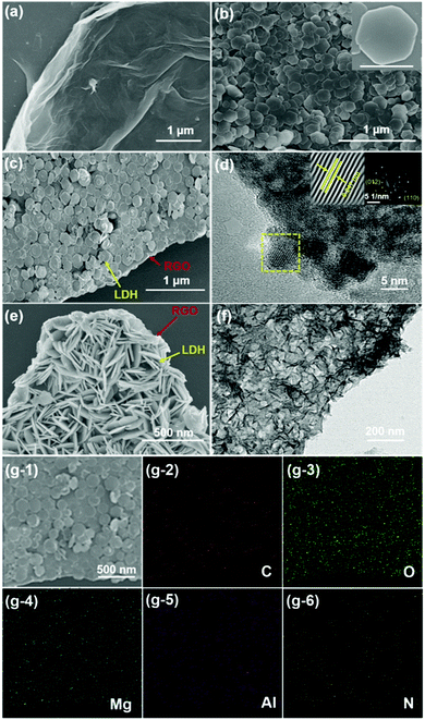
Field emission scanning electron microscopy (SEM) and transmission electron microscopy (TEM) were used to detect the morphologies and structures. For RGO, the SEM image (Fig. 1a) showed a two-dimensional (2D) sheet-like structure with a corrugated and scrolled edge, which was due to RGO agglomerating slightly through van der Waals interactions.28Fig. 1b shows the typically hexagonal platelet structure of pristine LDH with a diameter of 300 nm. Furthermore, a sandwich-like structure was observed in Fig. 1c. Thin-layer PEDOT:PSS/LDH nanoplates were coated on the RGO surface uniformly. Graphene clearly no longer formed a “petaloid” because RGO was exfoliated through π–π* interactions between RGO via charge-directed assembly.29 Furthermore, most LDH composites were vertically assembled on the surface of RGO due to the bridging of hydrogen bonds and electrostatic repulsions in LDHs,16 as shown in Fig. 1e. As shown in Fig. 1d, the interplanar spacing of 0.247 nm represented the (012) lattice plane of c-PEDOT:PSS/LDH.30 Clearly, c-PEDOT:PSS/LDH rather than i-PEDOT:PSS/LDH effectively enhanced the density distribution of LDH nanoplates on RGO (Fig. 1e and f), which improved the coverage rate of the corrosion–promoting surface of RGO. To some extent, the crystalline distribution of c-PEDOT:PSS/LDH can be accounted for by energy dispersive X-ray (EDX) elemental mapping analysis. Therefore, as shown in Fig. 1g-2 and g-6, C, N, O, Mg, and Al elements were exhibited on the surface of the composite in the SAED pattern (Fig. 1g-1), which was consistent with the results shown in Fig. 1c.
Fig. 2a shows the Raman spectra of RGO, i-LPG, and c-LPG, respectively. There were two distinct bands centred at 1341 (D-band) and 1580 cm−1 (G-band), which were attributed to asymmetrical defects on the surface and in-plane vibration of sp2 carbon atoms.15 The D-band and G-band were also observed in the spectra of c-LPG and i-LPG, but were blue-shifted (D-band at ∼1345 cm−1; G-band at 1596, 1604 cm−1).31 The LDH composites were confirmed to cover the surface of RGO without damaging its sheet structure. For the i-LPG and c-LPG hybrids, the prominent peaks were slightly different from those of RGO. The extra peaks present were characteristic of PEDOT:PSS/LDH, as shown in Fig. S2 (ESI†). Furthermore, the D band to G band intensity ratio (ID/IG) represented the disordered degree of carbon materials. This value decreased from 1.02 for RGO to 0.93 for c-LPG by calculation, suggesting that less basal plane sp2 domain and edge defects were present in RGO owing to the compensating effect of PEDOT:PSS/LDH for vacancies. However, the value increased gradually from 1.02 to 1.27 for i-LPG owing to the petal distribution of LDH, which formed unrepaired defects on the RGO surface. Furthermore, oxygen functional groups from the interlayer water of LDH increased the asymmetric structure of RGO.
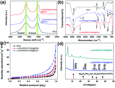 | ||
| Fig. 2 (a) Raman patterns, (b) FT-IR patterns, (c) N2 sorption isotherms, and (d) XRD patterns of LDH/PEDOT:PSS @RGO using two approaches. | ||
To better investigate the presence of functional groups in the samples, FT-IR spectroscopy32 was performed, as shown in Fig. 2b. All samples exhibited a broad peak at 3000–3500 cm−1, corresponding to stretching vibrations of C–H in PEDOT:PSS and O–H from the OH−/H2O in LDH layers, which agreed with the FT-IR analysis in Scheme 1d. Furthermore, bands for Mg–O stretching at around 784 cm−1 and Al–O stretching at 551 cm−1 confirmed the presence of the integral structure of LDHs. Additionally, the C![[double bond, length as m-dash]](https://www.rsc.org/images/entities/char_e001.gif) O and C–O stretching vibrations completely disappeared in the composites compared with RGO. Despite the modification, strong absorption on the surface of RGO was still observed, namely in the stretching vibration of hydroxide groups (3435 cm−1), skeletal aromatic vibration (1622 cm−1), and the alkoxy group stretching vibration (1064 cm−1). To better explore the inhibiting ability of these sheet composites, N2 adsorption/desorption measurements (Fig. 2c) were applied to reflect the surface area.33 All samples were classified as type IV isotherms with weak interactions. The BET surface areas of i-LPG and c-LPG were 20.5260 and 15.4387 m2 g−1, respectively, which were higher than that of RGO. The sample i-LPG exhibited the highest surface area owing to its vertical assembly on graphene oxide. In general, increasing the amount of insulating coverage not only reduced agglomeration of RGO, but also resulted in significant inhibition of corrosion properties. Furthermore, the higher surface area of the barrier composite was expected to contain water or ions, which are beneficial for reducing the connection between steel substrates and corrosion media.
O and C–O stretching vibrations completely disappeared in the composites compared with RGO. Despite the modification, strong absorption on the surface of RGO was still observed, namely in the stretching vibration of hydroxide groups (3435 cm−1), skeletal aromatic vibration (1622 cm−1), and the alkoxy group stretching vibration (1064 cm−1). To better explore the inhibiting ability of these sheet composites, N2 adsorption/desorption measurements (Fig. 2c) were applied to reflect the surface area.33 All samples were classified as type IV isotherms with weak interactions. The BET surface areas of i-LPG and c-LPG were 20.5260 and 15.4387 m2 g−1, respectively, which were higher than that of RGO. The sample i-LPG exhibited the highest surface area owing to its vertical assembly on graphene oxide. In general, increasing the amount of insulating coverage not only reduced agglomeration of RGO, but also resulted in significant inhibition of corrosion properties. Furthermore, the higher surface area of the barrier composite was expected to contain water or ions, which are beneficial for reducing the connection between steel substrates and corrosion media.
Fig. 2d shows the crystal structures obtained by XRD. For the LDH spectrum, diffraction peaks at 11.6° (003), 23.5° (006), 35.0° (012), 43.1° (015), 60.9° (110), and 62.3° (113) (JCPDS 22-0070) represented the LDH structure.34 In general, the series of (00l) reflections indicates the order along the layer stacking direction, such that the (003) characteristic diffraction peak will shift to smaller angles. As a result, PEDOT:PSS was solidified in the LDH structure in the c-PLG sample. Bulky anions (PSS−) will be incorporated into the interlayer structure of LDH, leading to subsequent widening of the lamellar space. Therefore, the diffraction peak at 2θ = 4.96° in i-PLG was the (003) diffraction peak, and the interlayer space had widened to 1.9 nm, as calculated using the Bragg equation:22
2d![[thin space (1/6-em)]](https://www.rsc.org/images/entities/char_2009.gif) sin sin![[thin space (1/6-em)]](https://www.rsc.org/images/entities/char_2009.gif) θ = nλ θ = nλ | (1) |
However, c-LPG showed similar characteristics to pristine LDH, indicating that no intercalation occurred and that PEDOT:PSS was solidified in the layers. Furthermore, a broad and wide diffraction peak (002) present at 25.7°, attributed to exfoliation of the layered RGO, was observed. After combining with RGO, the (002) peak of the composites had nearly disappeared owing to the low degree of crystallization.15
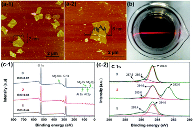
As shown in Fig. 3a, the SPM tapping mode images exhibited the structure of RGO and c-LPG.35 The nanosheets were irregular in shape and the lateral size had decreased due to damage during the ultrasonication assembly process. However, the thickness of the assembled RGO ranged from 4.5 to 6.2 nm, which was thicker than pristine RGO. Generally, the thickness of the Brucite-type layers and intercalated LDH was around 0.5 nm from our previous discussion. Therefore, it was rationalized that PEDOT:PSS/LDH was significantly adsorbed on the surface of RGO. XPS spectra of c-LPG were recorded to investigate the element composition and molecular structure of the materials, as shown in Fig. 3c. Clearly, peaks at 780.4 and 795.4 eV were attributed to Al 2p and Al 2s, while peaks at 73.5 and 118.5 eV belonged to Mg 2p, Mg 2s. The Mg![[thin space (1/6-em)]](https://www.rsc.org/images/entities/char_2009.gif) :
:![[thin space (1/6-em)]](https://www.rsc.org/images/entities/char_2009.gif) Al ratio was up to 2.3
Al ratio was up to 2.3![[thin space (1/6-em)]](https://www.rsc.org/images/entities/char_2009.gif) :
:![[thin space (1/6-em)]](https://www.rsc.org/images/entities/char_2009.gif) 1, indicating the presence of LDH composites. Though the peak at 164.0 eV, corresponding to S 2p, was relatively low, it still indicated sulfonate anions from PSS.22 Evidently, C 1s spectra associated with carbon functional groups and the graphite structure were split into three characteristic peaks: 282.6 eV (C–O–C), 284.6 eV (C–C), and 285.6 eV (O–C
1, indicating the presence of LDH composites. Though the peak at 164.0 eV, corresponding to S 2p, was relatively low, it still indicated sulfonate anions from PSS.22 Evidently, C 1s spectra associated with carbon functional groups and the graphite structure were split into three characteristic peaks: 282.6 eV (C–O–C), 284.6 eV (C–C), and 285.6 eV (O–C![[double bond, length as m-dash]](https://www.rsc.org/images/entities/char_e001.gif) O).36 The results showed that oxygenated groups were inserted into the LDH-modified RGO hybrid materials owing to the relatively high intensity of C–O–C and O–C
O).36 The results showed that oxygenated groups were inserted into the LDH-modified RGO hybrid materials owing to the relatively high intensity of C–O–C and O–C![[double bond, length as m-dash]](https://www.rsc.org/images/entities/char_e001.gif) O.
O.
Morphology and interface analysis
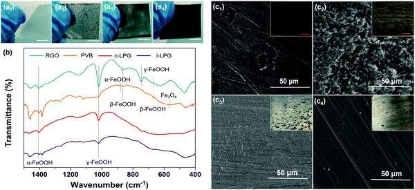
The 3D morphological variations in different coatings were investigated using confocal laser scanning microscopy. The surfaces were smooth owing to the inert film coated on the polished steel substrates. However, the RGO coating was rougher than other coatings, meaning that aggregated RGO increased the coating defects existing in the PVB coating. For modified coatings, the irregular structures almost completely vanished and the areal surface roughness (Ra) decreased from 2.8 to 0.2 and 1.3 μm. The results indicated that PEDOT:PSS/LDH@RGO was not only distributed densely in the PVB coatings, but it was also flat enough to smooth out the roughness.To further determine the coating surface morphology, SEM images of the prepared PVB coatings on substrates were obtained, as shown in Fig. 5. The PVB coating without modification exhibited microholes when the organic solvent was evaporated. Therefore, corrosive media diffused easily into the substrates, allowing further corrosion to occur. It was necessary to add layered materials to compensate for the holes and extend the diffusion path.37 For the coating with RGO, aggregated nanosheets resulted in a rougher surface and messy cracks. Therefore, coating defects were exacerbated and led to more serious corrosion, which was consistent with the discussion in Fig. 4. Although the adhesion of the RGO coating was enhanced, easily agglomerated RGO increased the extent of the uneven PVB distribution. However, the i-LPG coating was easier to peel off, which might be due to the excessive pigment thickness. Compared with PVB coating, the cross-sectional SEM images of the c-LPG coating presented a similar thickness owing to their even distribution. Furthermore, the coating was as flat as the pure PVB coating from surface observation, which indicated effective hole filling. This demonstrated that the dense and uniform coatings extended the diffusion pathway of corrosive ions and water macromolecules, while minimizing the exposed substrate area.
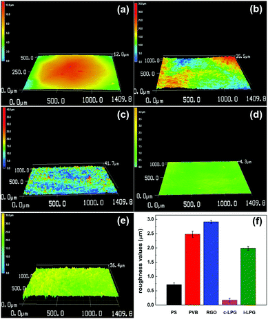 | ||
| Fig. 4 Confocal laser microscopy images of five different samples (a) PS, (b) PVB, (c) RGO, (d) c-LPG, and (e) i-LPG. (f) Evolution of roughness values of the substrates with and without coating. | ||
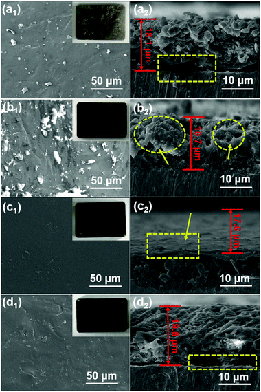 | ||
| Fig. 5 Top-view SEM images and SEM cross-sectional images of (a) PVB, (b) RGO, (c) c-LPG, and (d) i-LPG. Inset images are optical photographs of the corresponding coatings (3 cm × 2 cm). | ||
Electrochemical measurements
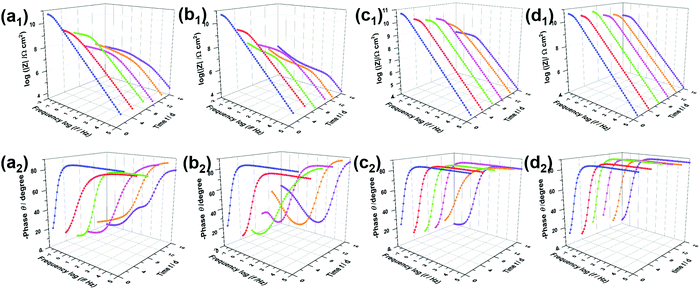
The open circuit potential38 (Fig. S4, ESI†) can be measured to determine the protective effect of the coating systems. The changing potential indicates an increasing corrosion state. EIS measurements were used to characterize the corrosion resistance of coated steel sheets immersed in 3.5 wt% NaCl solution.39 It is generally agreed that a higher impedance modulus at a lower frequency in the Bode diagram indicates a better anti-corrosion property of the coating.40Fig. 6a shows the Bode plots of PVB immersed in NaCl solution for 16 days, with a low-frequency impedance modulus (|Z|0.01![[thin space (1/6-em)]](https://www.rsc.org/images/entities/char_2009.gif) Hz) of up to 6.1 × 10¹⁰ Ω cm2 owing to the hydrophobicity of PVB. Notably, the results after immersion for 4 days confirmed that the PVB coating did not block the corrosive media effectively, owing to the coating defects. Similarly, new peaks presented in the middle-frequency region in the Bode phase angle diagrams and impedance modulus had decreased sharply. In the initial immersion, the Bode plots of the RGO coating were characterized by a straight line with |Z|0.01
Hz) of up to 6.1 × 10¹⁰ Ω cm2 owing to the hydrophobicity of PVB. Notably, the results after immersion for 4 days confirmed that the PVB coating did not block the corrosive media effectively, owing to the coating defects. Similarly, new peaks presented in the middle-frequency region in the Bode phase angle diagrams and impedance modulus had decreased sharply. In the initial immersion, the Bode plots of the RGO coating were characterized by a straight line with |Z|0.01![[thin space (1/6-em)]](https://www.rsc.org/images/entities/char_2009.gif) Hz = 7.1 × 10¹⁰ Ω cm2, such as the PVB film attributed to corrosion resistance. However, |Z|0.01
Hz = 7.1 × 10¹⁰ Ω cm2, such as the PVB film attributed to corrosion resistance. However, |Z|0.01![[thin space (1/6-em)]](https://www.rsc.org/images/entities/char_2009.gif) Hz dropped to 1.0 × 10⁸ Ω cm2, which was lower than that of the PVB coating, and phase angle peaks appeared in the low and medium-frequency regions when progressive ions penetrated after 7 days. Therefore, aggregated RGO in the coating matrix was confirmed to cause more serious corrosion owing to micro-galvanic corrosion resulting from disorderly contact between RGO and steel/RGO. As shown in Fig. 6d and e, the sluggish electrolyte penetrating through the coatings i-LPG and c-LPG resulted in higher impedance moduli (8.1 × 10¹⁰ Ω cm2 and 6.3 × 10¹⁰ Ω cm2). Meanwhile, these two coatings showed significant long-term corrosion inhibition results owing to the high impedance modulus throughout. Furthermore, the responses in the Bode-phase plots were only obtained at high frequency, which showed the significant barrier effect without promotion of corrosion.
Hz dropped to 1.0 × 10⁸ Ω cm2, which was lower than that of the PVB coating, and phase angle peaks appeared in the low and medium-frequency regions when progressive ions penetrated after 7 days. Therefore, aggregated RGO in the coating matrix was confirmed to cause more serious corrosion owing to micro-galvanic corrosion resulting from disorderly contact between RGO and steel/RGO. As shown in Fig. 6d and e, the sluggish electrolyte penetrating through the coatings i-LPG and c-LPG resulted in higher impedance moduli (8.1 × 10¹⁰ Ω cm2 and 6.3 × 10¹⁰ Ω cm2). Meanwhile, these two coatings showed significant long-term corrosion inhibition results owing to the high impedance modulus throughout. Furthermore, the responses in the Bode-phase plots were only obtained at high frequency, which showed the significant barrier effect without promotion of corrosion.
The EIS results were also fitted by ZView software using equivalent electric circuits (EEC),41 as shown in Fig. 7. The fitting lines corresponding to EEC are shown in Fig. S7 (ESI†). Specifically, Rs, Rc, and CPEc are the solution resistance, coating resistance, and coating capacitance, respectively. When the coating was damaged, the electrochemical behaviour at the steel interface consisted of charge-transfer resistance (Rct) and Cdl corresponded to double-layer capacitance,42 because the data were not perfectly fitted owing to the interface effect and capacitance deviation. The constant phase element (CPE) was used to substitute Cdl,15 and the impedance was expressed by the following equation:
 | (2) |
| Cdl = Y0(ωmax)n−1 | (3) |
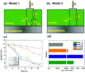 | ||
| Fig. 7 (a and b) Equivalent circuits used for EIS data fitting, (c) logarithm for evolution of coating resistance Rc with immersion in 3.5 wt% NaCl solution, and (d) corrosion rate index Rct−1. | ||
Usually, the CPEc value is associated with the barrier property of the coating, which can increase gradually as the coating absorbs water with a higher dielectric constant.43 Aggressive electrolytes and water gradually reached the metal through cracks or pores in the coatings. Therefore, a diffusion process appeared in the steel interfaces, indicating severe metal corrosion. The distribution of Rc must be determined to analyse the barrier properties of the coatings. Clearly, in Fig. 7c, the Rc of the PVB coating gradually decreased from 5.2 × 10¹⁰ to 3.8 × 10⁷ Ω cm2 during immersion for 7 days. The coating with RGO exhibited the lowest value of Rc, indicating the worst anti-corrosion ability. This can be attributed to the complex connection (increasing coating defects) between graphene or between graphene and substrates. A conductive pathway formed among the corrosive media, RGO, and steel interfaces. However, the i-LPG and c-LPG coatings not only showed the highest Rc values (8.0 × 10¹⁰ and 7.2 × 10¹⁰ Ω cm2), but also showed a slightly increasing trend. Fig. 7d shows the instantaneous corrosion rate values of Rct−1 for steel coated with different coatings after immersion for 16 days, which was sensitive to aggressive ions.38 The values of Rct−1 varied from 5.9 × 10⁻⁷ Ω−1 cm−2 to 1.6 × 10⁻¹⁰ Ω−1 cm−2. The highest corrosion rates were recorded for the RGO coating, while the lowest corrosion rate was recorded for the c-LPG coating. The overall distribution of Rct−1 indicated that the i-LPG film had a significant barrier effect and inhibition ability, while the RGO coating more easily lost its effect owing to the conductive connection or cluster.9
Investigation of self-healing performance
The LEIS technique has been widely used to study the local corrosion and dynamic development of passivation films, and helped us explore the microscopic corrosion mechanism.44 Furthermore, LEIS is also used to research the effect of surface coating on metal protection and coating defects or destruction. As shown in Fig. 8 and Fig. S8 (ESI†), the electrochemical behaviour of coatings with scratches during immersion for 18 h was discussed via LEIS. The potential signals in the vicinity of scratches were recorded and converted to a local current density using Ohm's law:44 | (4) |
 | (5) |
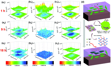 | ||
| Fig. 8 LEIS local impedance maps of (a) PVB, (b) RGO, and (c) c-LPG for immersion of 1, 9, and 18 h; (d) schematic representation of self-healing mechanism of c-LPG when the coating was destroyed. | ||
With increasing immersion time, the corrosion area and corrosion current density were increased owing to the media aggressively penetrating into the steel substrates through coating defects or pores. Notably, the RGO film showed the roughest 3D topography map (lowest corrosion local impedance), which meant that adjacently aggregated RGO not only caused an uneven coating surface and interior with defects, but also served as a cathode, leading to micro-galvanic corrosion.45 A large amount of the progressive ions infiltrated into the entire steel sheets compared with the pure PVB composite coating. The corroded area was widened by the corrosion ions or oxygen penetrating into the coating along the scratches. However, c-LPG reduced the micro-galvanic corrosion and showed a significant physical barrier effect. To our surprise, for scratched c-LPG, corrosion behaviour clearly occurred in the damaged area after immersion for 9 h owing to oxygen being consumed by the cathodic reaction. However, the extent of corrosion was much lower than that of the other specimens after immersion for 18 h. Furthermore, the corrosion activity was suppressed by covering with the PEDOT:PSS film because the corrosion current density declined.
The self-healing action of c-LPG can be simply be attributed to PEDOT:PSS being fixed in the interlayers rather than intercalated, allowing it to escape easily from the LDH sheets.23,46 Typically, with increasing immersion time, Mg(OH)2 from the LDHs is gradually replaced by OH− and Cl− to produce Mg2+ ions,20 as expressed by the following equations:
| Mg(OH)2 + Cl− → Mg(OH)Cl + OH− | (6) |
| Mg(OH)Cl + Cl− → MgCl2 + OH− | (7) |
As shown in Fig. 8e, the PEDOT:PSS particles with excess fixed negative charge became crosslinked by bivalent Mg2+ owing to electrostatic interactions in the PVB matrix.20 Accordingly, a 3D network was formed in the blend due to ionic crosslinking. This film could be used to fill the defects during the corrosion process.
Material protection mechanism
The corrosion resistance mechanism is generally related to the corrosion product–rust layer structure. As shown in Fig. 9 and Fig. S9, Table S1 (ESI†), a loose porous corrosion product was observed in the PS electrode. A large number of yellow rust layers and a few black rust layers were present in the digital image of PS, which were generated in the anode and cathode region, respectively. SEM images confirmed this conclusion due to the spherical goethite (α-FeOOH) and lump lepidocrocite (γ-FeOOH) present, which were consistent with the FT-IR results for the RGO electrode.Generally, the main component of the rust layer is γ-FeOOH if the corrosive medium has not completely infiltrated into the substrates. In other words, though the content of dissolved oxygen in the rust layer/metal interface is relatively high, the reduction efficiency of γ-FeOOH is low. It is difficult for the reduction reaction to take place, and the reaction at the anode and cathode can be written as:
| Fe2+ → Fe3+ + e− | (8) |
| O2 + 2H2O + 4e− → 4OH− | (9) |
As the corrosion rate is controlled by the cathode region reaction, then icorr = iO2. To our surprise, the excellent barrier properties of insulated graphene prevented the oxygen diffusion. As a result, only a little γ-FeOOH, rather than akaganeite (β-FeOOH), was found beneath the i-LPG and c-LPG substrates, as shown in the FT-IR spectra.
The corrosion product of the RGO coating was dense β-FeOOH, Fe3O4, and other loose ingredients, including α-FeOOH and γ-FeOOH. However, the reduction efficiency of β-FeOOH was so high that external disturbance around the corrosion potential (micro-galvanic corrosion) might lead to a severe reduction reaction, which can be expressed as:
| Fe2+ + 8FeOOH + 2e− → 3Fe3O4 + 4H2O | (10) |
For the PVB coating, dense β-FeOOH without influence prevents further diffusion of the invasive media, so scanty magnetite (Fe3O4) is generated owing to the low content of dissolved oxygen in the rust layers/metal interface.
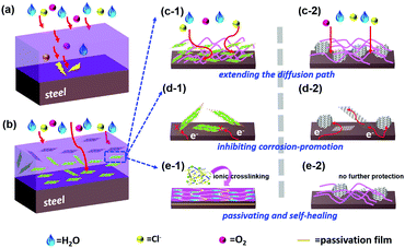
Clearly, LDH/PEDOT:PSS@RGO in the coating formulation with PVB can improve adhesion and mechanical properties by increasing interactions between RGO composites and steel. The coating structure on the steel surface provided a barrier and passivating film for the diffusion of Cl−, H2O, and O2 owing to the extremely 2D layered structure and inner connection resistance, as shown in Scheme 2. Specifically, three reasons can be considered. First, the lamellar structure of graphene has a good physical shielding effect, denoted as a “labyrinth effect”, which prolongs the permeation path of the corrosive medium, thereby achieving anti-corrosion properties for metal interfaces. Second, the failed RGO coating is likely to accelerate the corrosion process of steel owing to its more positive potential (+0.15 V vs. SCE)7 compared with mild steel (−0.44 V vs. SCE).47 However, RGO passivated by the insulating MgAl-LDH effectively reduces the cathode area. Galvanic corrosion consists of four elements, namely, the cathode, anode, electrolyte, and conductor. When one of these links disappears, corrosion will stop immediately. Finally, the passivating Fe2O3 layer formed at the polymer/metal interface, which shifted the potential to anodic sides to prevent further corrosion. The crosslinking PEDOT:PSS film also further delayed the corrosion reaction at the metal/solution interface.
Conclusions
We successfully obtained positively charged LDH/PEDOT:PSS through hydrothermal treatment and anion exchange. The hexagonal structure of LDH was well preserved, while the interlayer spacing increased owing to the pillaring effect of PSS macromolecules in the anion exchange process. However, LDH covered PEDOT between the layers along the PSS chain and formed a petaloid structure. LDH/PEDOT:PSS can be electrostatically assembled with RGO to yield colloidal suspensions. Furthermore, LDH/PEDOT:PSS@RGO not only avoided micro-galvanic corrosion, but also promoted the formation of a passivating film at the steel/solution interface. Owing to ionic crosslinking of this polymer, the coating had a self-healing effect when the LDHs were damaged to generate Mg2+. To our knowledge, this is the first example of using LDH/PEDOT:PSS fabricated with RGO to form multifunctional and externally insulating 2D nanomaterials.Experimental
Reagents
All chemicals were analytical reagent (AR) grade and directly used without further purification. Magnesium nitrate [Mg(NO3)2·6H2O], aluminium nitrate [Al(NO3)3·9H2O], hydrate hydrazinium hydrate (N2H4·H2O), ammonia (NH3·H2O, 25–28%), and sodium hydroxide (NaOH) were purchased from Aladdin Chemical Reagent Co., Ltd. Poly(3,4-ethylenedioxythiophene) (PEDOT:PSS) was purchased from Sigma-Aldrich Co., Ltd. Deionized water and other organic solvents were used in all experiments.Synthesis of LDH/PEDOT:PSS
The LDH precursors were prepared using the co-precipitation method.48 The products were synthesized in two steps, namely, exfoliation and anion exchange.49 First, Mg Al nitrate LDH was synthesized by adding pristine LDHs to a mixed solution of NaNO3 and HNO3 under a nitrogen atmosphere for 1 day.50 The exfoliated LDH was then obtained by dispersing precursors in formamide under a nitrogen atmosphere and agitating for 3 days. After centrifuging the colloid, intercalation of LDH/PEDOT:PSS was conducted in a recombination reaction, followed by dispersing nitrate LDH colloid in a formamide solution of negatively charged PEDOT:PSS (10 mmol) under vigorous stirring. LDH/PEDOT:PSS was then collected after centrifugation, washing, and drying steps.The co-blending LDH/PEDOT:PSS was prepared using a hydrothermal method.23 PEDOT:PSS was solidified in the LDH galleries. Briefly, Mg(NO3)2·6H2O (6 mmol), Al(NO3)3·9H2O (3 mmol), and mixed alkali (NaOH and Na2CO3, 12 mmol) were dissolved in deionized water (50 mL). Next, PEDOT:PSS aqueous solution (6 mL) was mixed with the above dispersion medium rapidly and the resulting gel was transferred into a Teflon-lined stainless-steel autoclave. After hydrothermal treatment at 120 °C for 16 h and drying, the powdered product was obtained.
Fabrication of LDH/PEDOT:PSS@RGO composite
LDH/PEDOT:PSS and RGO were combined using charge-directed self-assembly.49 The hybrid nanosheet was dispersed in formamide, and then flocculated by mixing with the GO suspension (5 g L−1), and the mixture was kept at 65 °C for 5 h. The product was centrifuged at 15![[thin space (1/6-em)]](https://www.rsc.org/images/entities/char_2009.gif) 000 rpm for 30 min, and the solid product was freeze-dried. The LDH/PEDOT:PSS/RGO material was obtained by reduction with N2H4·H2O. Finally, LDH/PEDOT:PSS@RGO was obtained after washing with deionized water and centrifuging, followed by freeze-drying overnight.
000 rpm for 30 min, and the solid product was freeze-dried. The LDH/PEDOT:PSS/RGO material was obtained by reduction with N2H4·H2O. Finally, LDH/PEDOT:PSS@RGO was obtained after washing with deionized water and centrifuging, followed by freeze-drying overnight.
Coating preparation
LDH/PEDOT:PSS@RGO coatings were constructed using a spin-coating technique. PVB film is a translucent film with no impurities and a smooth surface, and is thin enough for study on the coating/substrate interface, compared with epoxy resin.51 Prior to coating, LDH/PEDOT:PSS@RGO composites (0.1 g) were uniformly dispersed in methanol (20 mL) under vigorous stirring for 1 h, and PVB (2 g) was added into the existing dispersion. The mixture was stirred for an additional 1 day to obtain the LDH/PEDOT:PSS@RGO-modified PVB coating. The suspension was spin-coated onto a pre-cleaned steel substrate and dried at ambient temperature for 24 h. For a comparison specimen, RGO (0.1 g) was embedded into PVB using an identical spin-coating process. The pure PVB coatings and bare steel substrate were prepared simultaneously.Material characterization
Crystal structures were analysed using a Bruker D8 Advance X-ray diffractometer (XRD) with Cu Kα radiation (λ = 0.154 nm) at 40 kV and 30 mA. Transmission electron microscopy (TEM; JEOL-2100) and scanning electron microscopy (SEM; Hitachi S4800) were used to investigate the morphology. Fourier transform infrared (FT-IR) spectra were recorded on a Thermo Nicolet 6700 instrument. X-ray photoelectron spectroscopy (XPS) was used to detect the elemental composition and compound structure with a Kratos AXIS ULTRA instrument. The specific surface area was measured using the Brunauer–Emmett–Teller (BET) method using an ASAP2020M analyzer. Raman spectroscopy was performed using a laser Raman microscope (Renishaw inVia Reflex). The surface roughness and ζ-potential were measured by confocal laser scanning microscopy (CLSM, KEYENCE VK-X200K) and using a dynamic light-scattering particle size analyzer (Malvern Zetasizer Nano ZS). The morphology of the hybrid RGO materials was recorded by scanning probe microscopy (SPM) using a Vecco Dimension 3100 instrument.Electrochemical and self-healing measurement
The conventional electrochemical tests for corrosion research were conducted in a three-electrode system on a Modulab XM electrochemical workstation (Solartron).52 These coatings were tested with three parallel specimens. In general, the coating samples were used as the working electrode, while the counter and reference electrodes were a platinum plate and a saturated calomel electrode (SCE), respectively. Electrochemical impedance spectroscopy (EIS) was recorded in a cell with 3.5 wt% NaCl solution. Furthermore, localized electrochemical impedance spectroscopy (LEIS) was conducted to evaluate the localized corrosion process and coating/substrate interface using VersaScan electrochemical workstation (Princeton).Conflicts of interest
There are no conflicts to declare.Acknowledgements
We are grateful for the funding support provided by the “One Hundred Talented People” of the Chinese Academy of Sciences (No. Y60707WR04), the Key Research Program of Frontier Sciences of the Chinese Academy of Sciences (No. QYZDY-SSW-JSC009), and the Natural Science Foundation of Zhejiang Province (No. Y16B040008).Notes and references
- A. K. Geim and K. S. Novoselov, Nat. Mater., 2007, 6, 183–191 CrossRef CAS PubMed.
- Y. Zhu, S. Murali, W. Cai, X. Li, J. W. Suk, J. R. Potts and R. S. Ruoff, Adv. Mater., 2010, 22, 5226 CrossRef CAS.
- X. Shen, W. Cai, L. Zhong, D. Xie and X. Zhang, Ind. Eng. Chem. Res., 2016, 55, 8576–8585 CrossRef.
- A. J. Paulista Neto and E. E. Fileti, J. Phys. Chem. B, 2018, 122, 2578–2586 CrossRef CAS PubMed.
- Y. P. Hsieh, M. Hofmann, K. W. Chang, G. J. Jian, Y. Y. Li, K. Y. Chen, C. C. Yang, W. S. Chang and L. C. Chen, ACS Nano, 2014, 8, 443–448 CrossRef CAS PubMed.
- C. Cui, A. Lim and J. Huang, Nat. Nanotechnol., 2017, 12, 834–835 CrossRef CAS PubMed.
- W. Sun, L. Wang, T. Wu, M. Wang, Z. Yang, Y. Pan and G. Liu, Chem. Mater., 2015, 27, 2367–2373 CrossRef CAS.
- W. Sun, L. Wang, T. Wu, Y. Pan and G. Liu, J. Mater. Chem. A, 2015, 3, 16843–16848 RSC.
- Y. Liu, W. Hao, H. Yao, S. Li, Y. Wu, J. Zhu and L. Jiang, Adv. Mater., 2018, 30, 1705377 CrossRef PubMed.
- M. Schriver, W. Regan, W. J. Gannett, A. M. Zaniewski, M. F. Crommie and A. Zettl, ACS Nano, 2013, 7, 5763–5768 CrossRef CAS PubMed.
- S. Qiu, C. Chen, M. Cui, W. Li, H. Zhao and L. Wang, Appl. Surf. Sci., 2017, 407, 213–222 CrossRef CAS.
- L. Groenendaal, F. Jonas, D. Freitag, H. Pielartzik and J. R. Reynolds, Adv. Mater., 2000, 12, 481–494 CrossRef CAS.
- T. Saitoh, Y. Yoshida, T. Matsudo, S. Fujiwara, A. Dobashi, K. Iwaki, A. Y. Suzuki and C. Matsubara, Anal. Chem., 2017, 71, 4506–4512 CrossRef.
- M. H. Nazari and X. Shi, Polymer-Based Nanocomposite Coatings for Anticorrosion Applications, Springer International Publishing, 2016 Search PubMed.
- X. Luo, S. Yuan, X. Pan, C. Zhang, S. Du and Y. Liu, ACS Appl. Mater. Interfaces, 2017, 9, 18263–18275 CrossRef CAS PubMed.
- D. Zhou, Z. Cai, X. Lei, W. Tian, Y. Bi, Y. Jia, N. Han, T. Gao, Q. Zhang and Y. Kuang, Adv. Energy Mater., 2017, 1701905 Search PubMed.
- L. Ma, S. M. Islam, H. Liu, J. Zhao, G. Sun, H. Li, S. Ma and M. G. Kanatzidis, Chem. Mater., 2017, 29, 3274–3284 CrossRef CAS.
- M. L. Zheludkevich, J. Tedim, C. S. R. Freire, S. C. M. Fernandes, S. Kallip, A. Lisenkov, A. Gandini and M. G. S. Ferreira, J. Mater. Chem., 2011, 21, 4805–4812 RSC.
- R. C. Zeng, Z. G. Liu, F. Zhang, S. Q. Li, H. Z. Cui and E. H. Han, J. Mater. Chem. A, 2014, 2, 13049–13057 RSC.
- S. Ghosh, J. Rasmusson and O. Inganas, Adv. Mater., 1998, 10, 109 CrossRef.
- J. Yu, C. Wu, X. Zhang, F. Ye, M. E. Gallina, Y. Rong, I. C. Wu, W. Sun, Y. H. Chan and D. T. Chiu, Adv. Mater., 2012, 24, 3498–3504 CrossRef CAS PubMed.
- J. Zhao, S. Xu, K. Tschulik, R. G. Compton, M. Wei, D. O'Hare, D. G. Evans and X. Duan, Adv. Funct. Mater., 2015, 25, 2745–2753 CrossRef CAS.
- X.-J. Liu, W. Wang, Y.-H. Chen, J. A. A. Valinton, Y.-H. Chan and C.-H. Chen, ACS Appl. Nano Mater., 2018, 1, 55–64 CrossRef CAS.
- M. J. Hollamby, D. Fix, I. Dönch, D. Borisova, H. Möhwald and D. Shchukin, Adv. Mater., 2011, 23, 1361–1365 CrossRef CAS PubMed.
- L. Ma, S. M. Islam, C. Xiao, J. Zhao, H. Liu, M. Yuan, G. Sun, H. Li, S. Ma and M. G. Kanatzidis, J. Am. Chem. Soc., 2017, 139, 12745–12757 CrossRef CAS PubMed.
- G. Paul, C. Bisio, I. Braschi, M. Cossi, G. Gatti, E. Gianotti and L. Marchese, Chem. Soc. Rev., 2018, 47, 5684–5739 RSC.
- S. Kee, N. Kim, B. S. Kim, S. Park, Y. H. Jang, S. H. Lee, J. Kim, J. Kim, S. Kwon and K. Lee, Adv. Mater., 2016, 28, 8555 CrossRef CAS.
- Y. Zhang, D. Du, X. Li, H. Sun, L. Li, P. Bai, W. Xing, Q. Xue and Z. Yan, ACS Appl. Mater. Interfaces, 2017, 9, 31699–31709 CrossRef CAS PubMed.
- D. Du, X. Wu, S. Li, Y. Zhang, W. Xing, L. Li, Q. Xue, P. Bai and Z. Yan, J. Mater. Chem. A, 2017, 5, 8964–8971 RSC.
- X. Liu, C. Wang, Y. Dou, A. Zhou, T. Pan, J. Han and M. Wei, J. Mater. Chem. A, 2014, 2, 1682–1685 RSC.
- M. S. Dresselhaus, A. Jorio, M. Hofmann, G. Dresselhaus and R. Saito, Nano Lett., 2010, 10, 751–758 CrossRef CAS PubMed.
- N. H. N. Azman, H. N. Lim and Y. Sulaiman, Electrochim. Acta, 2016, 188, 785–792 CrossRef.
- T. Tang, W. J. Jiang, S. Niu, N. Liu, H. Luo, Q. Zhang, W. Wen, Y. Y. Chen, L. B. Huang and F. Gao, Adv. Funct. Mater., 2018, 28, 1704594 CrossRef.
- V. R. R. Cunha, P. A. D. Petersen, M. B. Gonçalves, H. M. Petrilli, C. Taviotgueho, F. Leroux, M. L. A. Temperini and V. R. L. Constantino, Chem. Mater., 2012, 24, 1415–1425 CrossRef CAS.
- X. Guo, F. Zhang, D. G. Evans and X. Duan, Chem. Commun., 2010, 46, 5197–5210 RSC.
- N. Parhizkar, T. Shahrabi and B. Ramezanzadeh, Corros. Sci., 2017, 123, 55–75 CrossRef CAS.
- J. H. Xu, S. Ye, C. D. Ding, L. H. Tan and J. J. Fu, J. Mater. Chem. A, 2018, 6, 5887–5898 RSC.
- P. Du, S. Qiu, C. Liu, G. Liu, H. Zhao and L. Wang, New J. Chem., 2018, 42, 4201–4209 RSC.
- E. Saei, B. Ramezanzadeh, R. Amini and M. S. Kalajahi, Corros. Sci., 2017, 127, 186–200 CrossRef CAS.
- J. Tedim, M. L. Zheludkevich, A. N. Salak, A. Lisenkov and M. G. S. Ferreira, J. Mater. Chem., 2011, 21, 15464–15470 RSC.
- S. K. Saha and P. Banerjee, Mater. Chem. Front., 2018, 2, 1674–1691 RSC.
- S. U. Ofoegbu, T. L. P. Galvao, J. R. B. Gomes, J. Tedim, H. I. S. Nogueira, M. G. S. Ferreira and M. L. Zheludkevich, Phys. Chem. Chem. Phys., 2017, 19, 6113–6129 RSC.
- N. Sarkar, G. Sahoo, R. Das, G. Prusty, D. Sahu and S. K. Swain, Ind. Eng. Chem. Res., 2016, 55, 2921–2931 CrossRef CAS.
- T. Wang, L. Tan, C. Ding, M. Wang, J. Xu and J. Fu, J. Mater. Chem. A, 2017, 5, 1756–1768 RSC.
- L. B. Coelho and M. G. Olivier, Corros. Sci., 2018, 136, 292–303 CrossRef CAS.
- E. M. Moujahid, M. Dubois, A. Jeanpierre Besse and F. Leroux, Chem. Mater., 2005, 17, 373–382 CrossRef CAS.
- V. Hotař and A. Hotař, Corros. Sci., 2018, 133, 141–149 CrossRef.
- J. Yu, Q. Wang, D. O'Hare and L. Sun, Chem. Soc. Rev., 2017, 46, 5950–5974 RSC.
- S. Werner, V. W. H. Lau, S. Hug, V. Duppel, H. Clausen-Schaumann and B. V. Lotsch, Langmuir, 2013, 29, 9199–9207 CrossRef CAS PubMed.
- L. Wang, J. Shi, Y. Zhu, Q. He, H. Xing, J. Zhou, F. Chen and Y. Chen, Langmuir, 2012, 28, 4290–4295 Search PubMed.
- X. Lin, S. Yan, B. Zhou, K. Wang, J. Zhang and G. Luo, Green Chem., 2017, 19, 2155–2163 RSC.
- S. Pourhashem, M. R. Vaezi, A. Rashidi and M. R. Bagherzadeh, Corros. Sci., 2016, 115, 78–92 CrossRef.
Footnote |
| † Electronic supplementary information (ESI) available: Fig. S1–S9: FT-IR and ζ-potential, Raman spectroscopy; AFM image; open circuit potential, EIS for steel sheets and component; LEIS of i-LPG sample and SEM and optical images for substrates; Table S1: steel elements composition data (EDS); the experimental process of graphene oxide. See DOI: 10.1039/c8qm00455b |
| This journal is © the Partner Organisations 2019 |

