High performance solution-processed organic yellow light-emitting devices and fluoride ion sensors based on a versatile phosphorescent Ir(III) complex†
Xiaolong
Yang
 a,
Zhao
Feng
a,
Jingshuang
Dang
b,
Yuanhui
Sun
a,
Guijiang
Zhou
a,
Zhao
Feng
a,
Jingshuang
Dang
b,
Yuanhui
Sun
a,
Guijiang
Zhou
 *a and
Wai-Yeung
Wong
 *c
*c
aDepartment of Chemistry, School of Science, MOE Key Laboratory for Nonequilibrium Synthesis and Modulation of Condensed Matter, Xi’an Jiaotong University, Xi’an 710049, China. E-mail: zhougj@mail.xjtu.edu.cn
bSchool of Chemistry and Chemical Engineering, Shaanxi Normal University, Xi’an 710119, China
cDepartment of Applied Biology and Chemical Technology, The Hong Kong Polytechnic University, Hung Hom, Hong Kong, China. E-mail: wai-yeung.wong@polyu.edu.hk
First published on 16th December 2018
Abstract
An efficient phosphorescent iridium(III) complex (BPyPmIr) has been prepared with the asymmetric structure of (C^N1)(C^N2)Ir(acac) in which C^N1 and C^N2 are 5-(dimesitylboranyl)-2-phenylpyridine and 2-(2,4-difluorophenyl)pyrimidine, respectively, and acac is acetylacetonate. At room temperature, BPyPmIr shows a very high photoluminescence quantum yield (PLQY) of 0.88 in THF and nearly unity in doped films. A solution-processed yellow OLED based on BPyPmIr gives the maximum luminance (Lmax), external quantum yield (EQE), current efficiency (CE), and power efficiency (PE) of 54![[thin space (1/6-em)]](https://www.rsc.org/images/entities/char_2009.gif) 378 cd m−2, 18.7%, 62.8 cd A−1, and 60.9 lm W−1, respectively, with very low efficiency roll-off at a high luminance of 1000 cd m−2, which are among the highest efficiencies ever reported for solution-processed yellow OLEDs. Furthermore, because of the strong boron–fluoride ion interactions between the dimesitylboryl moiety and F− ions, this Ir(III) complex can be used as an efficient “color-switch” sensor for detecting F− ions. Besides its high sensitivity and selectivity, the detection limit of this Ir(III) complex is as low as 1.55 × 10⁻⁷ M.
378 cd m−2, 18.7%, 62.8 cd A−1, and 60.9 lm W−1, respectively, with very low efficiency roll-off at a high luminance of 1000 cd m−2, which are among the highest efficiencies ever reported for solution-processed yellow OLEDs. Furthermore, because of the strong boron–fluoride ion interactions between the dimesitylboryl moiety and F− ions, this Ir(III) complex can be used as an efficient “color-switch” sensor for detecting F− ions. Besides its high sensitivity and selectivity, the detection limit of this Ir(III) complex is as low as 1.55 × 10⁻⁷ M.
Introduction
As one of the focus topics in organic optoelectronics, phosphorescent cyclometalated iridium(III) complexes have drawn increasing attention for their use as electrophosphorescent emitters in organic light-emitting devices (OLEDs),1–5 materials converting light into electricity in solar cells,6,7 and phosphorescent probes in biosensing8–10 or ion sensors.11–13 The widely used cyclometalated Ir(III) complexes usually consist of three identical cyclometalating ligands (C^N) or two identical C^N ligands and one ancillary ligand (LX), i.e., they have symmetric structures summarized like this: (C^N)3Ir or (C^N)2Ir(LX). Generally, the photophysical properties of the (C^N)2Ir(LX) complexes are similar to those of the corresponding (C^N)3Ir complexes, because the ancillary ligand usually has a little impact on the photophysical properties of the Ir(III) complexes, while the C^N ligands show a dominant influence on the emission colors as well as the photoluminescence quantum yields (PLQYs) of the Ir(III) complexes.1,14 Therefore, a successful strategy for tuning the photophysical properties of the Ir(III) complexes is to modify the C^N ligands, and the modifications are usually made for all C^N ligands in one Ir(III) complex. However, recent research studies have demonstrated that if only one C^N ligand in an Ir(III) complex is modified to form an asymmetric structure, the photophysical and charge transport properties can be finely tuned to achieve better performance in OLEDs.15–17Highly sensitive and selective sensors for F− ions are in great demand because of the critical role of F− ions in human health as well as environmental science; therefore, numerous F− ion sensors have been developed based on electrochemical methods,18 hydrogen-bonding interactions,19 and Lewis acid–base interactions.20 Among these techniques, sensors utilizing the boron–fluoride ion interaction have been actively studied.21–23 Compounds bearing dimesitylboryl (B(Mes)2) moieties usually are highly sensitive and selective to F− ions. Upon binding to F− ions, a lot of B(Mes)2-based sensors show that emissions are quenched by F− ions, leading to a “turn-off” effect.21,24–27 However, for practical applications, “turn-on” sensors are more attractive because their signal detection is more effective.28–30 It is even better if sensors can emit different colors after the addition of the tested object, which can be named “color-switch” sensors. Thus, the development of “color-switch” sensors for F− ions is a more exciting research direction.
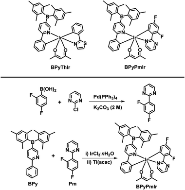
In this work, by combining the asymmetric structure design strategy and the good F− ion sensing ability of the B(Mes)2 group, we successfully prepared a phosphorescent cyclometalated Ir(III) complex (BPyPmIr) with the asymmetric structure of (C^N1)(C^N2)Ir(acac) in which C^N1 and C^N2 were 5-(dimesitylboranyl)-2-phenylpyridine and 2-(2,4-difluorophenyl)pyrimidine, respectively (Scheme 1). The photophysical investigations showed that the modification of one C^N ligand with the B(Mes)2 group could significantly increase the photoluminescence quantum yield (PLQY) to 0.88 in THF solution. Furthermore, a solution-processed yellow OLED fabricated using BPyPmIr as the emitter obtained the peak external quantum yield (EQE), current efficiency (CE) and power efficiency (PE) of 18.7%, 62.8 cd A−1 and 60.9 lm W−1, respectively, which are among the highest efficiencies ever reported for solution-processed yellow OLEDs.31–38 In addition, because of the B–F interaction between the B(Mes)2 moiety and F− ions, BPyPmIr exhibited high sensitivity and selectivity to F− ions. More importantly, the emission color changed from yellow to green during the addition of F− ions, exhibiting “color-switch” behavior, which is a highly desired merit for sensors.
Results and discussion
Synthesis and characterization
The complex BPyThIr was synthesized according to our previous study.17 Before the synthesis of BPyPmIr, the cyclometalating ligand 2-(2,4-difluorophenyl)pyrimidine (Pm) was obtained by reacting 2-chloropyrimidine with (2,4-difluorophenyl)boronic acid through the Suzuki-coupling reaction (Scheme 1). Then BPyPmIr was synthesized following the traditional method which involved two steps by first heating 1.0 equiv. of Pm, 1.0 equiv. of 5-(dimesitylboranyl)-2-phenylpyridine (BPy), and 1.0 equiv. of IrCl3·nH2O in solution to obtain a dichloro-bridged Ir(II) dimer and then stirring the dimer with thallium(I) acetylacetonate in CH2Cl2 at room temperature to give the final product. The final complex was confirmed by 1H and 13C NMR and mass spectroscopies (see Fig. S1 in the ESI†). The thermal stability of BPyPmIr was measured by thermogravimetric analysis (TGA) under a N2 atmosphere at a heating rate of 20 K min−1, and the corresponding 5% weight-reduction temperature (Td) was 218 °C, which was high enough for fabricating solution-processed OLEDs as well as detecting F− ions.Photophysical properties
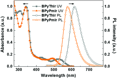
The UV-vis absorption and photoluminescence (PL) spectra of BPyPmIr and BPyThIr17 measured in THF solution at room temperature are depicted in Fig. 1, and the relevant data are listed in Table 1. The intense high-energy absorption bands with peaks <370 nm were assigned to the ligand centered 1ππ* transitions. The weak and broad low-energy absorption bands in the visible region could be assigned to a combination of the singlet and triplet metal-to-ligand charge-transfer (1MLCT and 3MLCT) transitions mixed with the ligand-to-ligand charge-transfer (1LLCT and 3LLCT) transitions. These assignments were supported by the theoretical calculation results (vide infra). The lowest energy absorption maximum of BPyPmIr (λabs = 495 nm) was blue-shifted compared with that of BPyThIr (λabs = 530 nm), showing the different influences of the Pm ligand and the 2-phenylthiazole (Th) ligand on the photophysical properties of the corresponding complexes. Under UV irradiation, BPyPmIr exhibited intense yellow emission in THF solution. Compared with the emission peaks of symmetric complexes bis(2-phenylthiozolato-N,C2′)iridium(acetylacetonate) [(Th)2Ir(acac)] (λem = 546 nm) and bis[2-(2,4-difluorophenyl)pyrimidinato-N,C2′]iridium(acetylacetonate) [(Pm)2Ir(acac)] (λem = 496 nm), those of asymmetric complexes BPyPmIr (λem = 578 nm) and BPyThIr (λem = 619 nm) were significantly red-shifted. Besides, compared with the PLQYs of (Th)2Ir(acac) (PLQY = 0.35), bis(2-phenylpyridinato-N,C2′)iridium(acetylacetonate) [(ppy)2Ir(acac)] (PLQY = 0.34) and other reported Ir(III) complexes,1,39–47 the PLQY of BPyPmIr was greatly increased to 0.88. The τp of BPyPmIr was estimated to be 0.75 μs, which was comparable to those of other reported Ir(III) complexes.1,39–47 In contrast, the λem of BPyPmIr was much closer to that of bis[5-(dimesitylboranyl)-2-phenylpyridinato-N,C2′]iridium(acetylacetonate) [(BPy)2Ir(acac)] (λem = 604 nm),48 implying that the BPy ligand had a great influence on the emission properties of BPyPmIr. However, although BPyPmIr had the same BPy ligand as BPyThIr, the emission peak of BPyPmIr (λem = 578 nm) was blue-shifted compared with that of BPyThIr (λem = 619 nm) (Fig. 1), which was in good agreement with the blue-shifted lowest energy absorption maximum of BPyPmIr (λabs = 495 nm) compared with that of BPyThIr (λabs = 530 nm). The result confirms that the second cyclometalating ligand can finely tune the photophysical properties; thus, this is a merit of developing Ir(III) complexes with asymmetric structures.| Complex |
λ
abs (log![[thin space (1/6-em)]](https://www.rsc.org/images/entities/char_2009.gif) ε)a [nm] ε)a [nm] |
λ em [nm] | PLQYa | τ p [μs] | HOMO/LUMOb [eV] |
|---|---|---|---|---|---|
| a Measured in THF at a concentration of ca. 10−5 M. b Calculated according to EHOMO = −(Eox + 4.8) eV and ELUMO = −(Ered + 4.8) eV. c Taken from ref. 17 for comparison. | |||||
| BPyPmIr | 338 (4.56), 398 (3.76), 495 (3.69) | 578 | 0.88 | 0.75 | −5.50/−2.89 |
| BPyThIr | 309 (4.40), 342 (4.44), 427 (3.62), 530 (3.53) | 619 | 0.89 | 0.93 | −5.26/−2.80 |
Theoretical calculations
To gain insight into the photophysical properties, we performed the density functional theory (DFT) and time-dependent density functional theory (TD-DFT) calculations. The frontier molecular orbitals (MOs) of the highest occupied molecular orbital (HOMO) and the lowest unoccupied molecular orbital (LUMO) calculated based on the optimized S0 geometry are depicted in Fig. 2a. The calculated energies in terms of wavelengths and the corresponding assignments are listed in Table S1 (see the ESI†). The calculated wavelengths for BPyThIr (λcal. = 544 nm) and BPyPmIr (λcal. = 501 nm) were close to the experimental absorption peaks, indicating the validity of the theoretical computation. As depicted in Fig. 2a, the LUMO of BPyPmIr was dominantly localized on the BPy ligand (94.1%) with neglected distribution on the Pm ligand (0.5%) (see Fig. S2 in the ESI†), which could explain the reason that the BPy ligand had a great influence on the emission properties of BPyPmIr. The HOMO of BPyPmIr involved a significant contribution from the d orbital of the Ir(III) center (51.9%), and the π orbitals of the chelated phenyl rings in the Pm ligand (13.2%) and the BPy ligand (20.1%). Therefore, the Pm ligand also had a notable influence on the HOMO of BPyPmIr. Because of the large contribution (>88%) from the HOMO → LUMO transition to both S0 → S1 and S0 → T1 transitions, both S0 → S1 and S0 → T1 absorption transitions were mainly assigned to the MLCT process. In addition, the chelated phenyl ring in the BPy ligand also made a considerable contribution (12.3%) to the LUMO of BPyPmIr, indicating the existence of the ππ* transition. Since the whole Pm ligand made 15.3% contribution to the HOMO and only 0.5% contribution to the LUMO, obvious charge transfer from the Pm ligand to the BPy ligand in the HOMO → LUMO transition implied the LLCT character. These results showed that the S0 → S1 and S0 → T1 absorption transitions of BPyPmIr could be assigned to mixed MLCT/LLCT/ππ* transitions, which were similar to the case of BPyThIr.17 As mentioned earlier, the Pm ligand made a notable contribution to the HOMO of BPyPmIr, and the calculated HOMO level was −5.14 eV, which was lower than that calculated for BPyThIr (−4.90 eV). Considering the comparable LUMO levels calculated for BPyPmIr (−2.12 eV) and BPyThIr (−2.02 eV), BPyPmIr possessed a larger HOMO–LUMO gap, and therefore displayed a blue-shifted low-energy absorption. This calculation result was in a good agreement with the experimental result. Further insight into the phosphorescence emission properties was obtained by calculating the natural transition orbital (NTO) based on the optimized T1 geometry. As shown in Fig. 2b, for BPyPmIr, the distribution patterns of hole orbitals and particle orbitals were very similar to those of the HOMO and LUMO, respectively. As listed in Table S2 (see the ESI†), the hole orbital of BPyPmIr was composed of contributions from the Ir(III) center (40.80%), the BPy ligand (46.51%), the Pm ligand (8.10%), and the acetylacetone (acac) ligand (4.59%), while the particle orbital was composed of contributions from the Ir(III) center (4.24%), the BPy ligand (93.77%), the Pm ligand (0.74%), and the acetylacetone ligand (1.25%). The weight of the hole → particle transition to the T1 state was calculated to be 99.8%. Therefore, the T1 → S0 emission transition was mainly assigned to the MLCT and ππ* together with some LLCT character. In detail, due to the incorporation of the second cyclometalating ligand (i.e., the Pm ligand), the refinement of the emission properties was realized by the LLCT process. Therefore, further refinement of the emission properties could be expected by meticulously designing the second cyclometalating ligand in future design of Ir(III) complexes.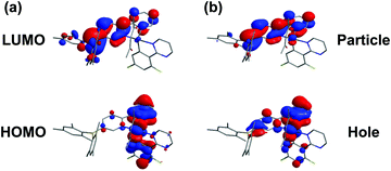 | ||
| Fig. 2 Plots of (a) the HOMO and LUMO of BPyPmIr calculated based on the optimized S0 geometry and (b) the NTO of BPyPmIr calculated based on the optimized T1 geometry. | ||
Electrochemical properties
The oxidation and reduction potentials of BPyPmIr were measured using cyclic voltammetry (CV) in acetonitrile solution calibrated with ferrocene as the internal standard under a nitrogen atmosphere (see Fig. S3 in the ESI†). During the anodic scan, BPyPmIr exhibited a quasi-reversible oxidation wave with a potential (Eox) of ca. 0.7 V, which was the typical oxidation potential of Ir centers in Ir(III) complexes.49–51 Due to the incorporation of the B(Mes)2 group into the pyridine ring, a quasi-reversible reduction wave was recorded with a potential (Ered) of ca. −1.91 V, which was located at a more positive position than those for other non-borylated Ir(III) complexes,52 indicating the improved electron-injection ability of BPyPmIr. The HOMO and LUMO energy levels of BPyPmIr were calculated from the oxidation and the reduction potentials (Table 1). In accordance with the theoretical calculation prediction, the HOMO level of BPyPmIr (−5.50 eV) was significantly lower than that of BPyThIr (−5.26 eV), demonstrating the stronger influence of the Pm ligand on the HOMO of BPyPmIr than that of the Th ligand on the HOMO of BPyThIr. In addition, the LUMO level of BPyPmIr (−2.89 eV) was lower than those of (ppy)2Ir(acac) (−2.74 eV)53 and (Th)2Ir(acac) (−2.19 eV),46 which could facilitate the electron-injection process in OLEDs.Electroluminescent properties
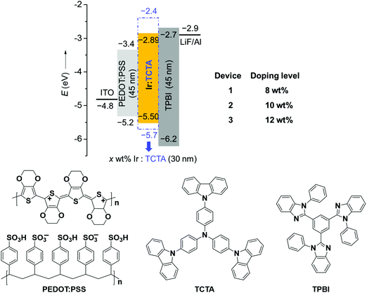
Considering the high PLQY and good solubility of BPyPmIr, we investigated the electroluminescent (EL) properties of BPyPmIr by fabricating solution-processed devices with a conventional structure of ITO/PEDOT:PSS (45 nm)/x wt% BPyPmIr:TCTA (30 nm)/TPBI (45 nm)/LiF (1 nm)/Al (100 nm). In these devices, poly(ethylenedioxythiophene):poly(styrenesulfonate) (PEDOT:PSS) was used to inject and transport holes to the emissive layer. The 4,4′,4′′-tri(N-carbazolyl)triphenylamine (TCTA) was used as the host, and the doping concentrations were 8 wt% (Device 1), 10 wt% (Device 2) and 12 wt% (Device 3). The 1,3,5-tris(N-phenylbenzimidazol-2-yl)benzene (TPBI) and LiF were used as the electron-transport and electron-injection materials, respectively. The detailed energy levels and the molecular structures of the materials used in the OLEDs are shown in Fig. 3.All of the devices could show intense yellow emissions, with their EL spectral profiles resembling the PL spectrum of the TCTA film doped with BPyPmIr at the 10 wt% level through the spin-coating method (Fig. 4a). The exclusive emission from the emissive layer indicated complete energy transfer from the TCTA host to the BPyPmIr emitter and good exciton confinement within the emissive layer because of the matchable energy level alignment between the BPyPmIr emitter and other functional materials (i.e., the host and charge transfer materials). Among these devices, Device 2 with the 10 wt% doping level showed the best performance (Table 2). The current density (J)–voltage (V)–luminance (L) curves and efficiency versus luminance plots are depicted in Fig. 4b–d and Fig. S4 and S5 (see the ESI†). Device 2 exhibited a very low turn-on voltage of 2.4 V with attractive performance evidenced by the maximum luminance (Lmax), external quantum yield (EQE), current efficiency (CE) and power efficiency (PE) of 54![[thin space (1/6-em)]](https://www.rsc.org/images/entities/char_2009.gif) 378 cd m−2, 18.7%, 62.8 cd A−1 and 60.9 lm W−1, respectively. In addition, the EQE and CE remained as high as 17.8% and 59.9 cd A−1, respectively, at a high luminance of 1000 cd m−2, showing very low efficiency roll-off less than 5%. To the best of our knowledge, the performance of Device 2 is among the best ever reported for solution-processed yellow OLEDs (Table 3).31–38 The high efficiencies could be attributed to the high PLQY (=0.99), short lifetime (= 1.08 μs) (Fig. S6 in the ESI†), efficient energy transfer and good exciton confinement within the emissive layer (Fig. 3). Besides, we also investigated the film-forming properties of this Ir(III) complex doping in TCTA with atomic force microscopy (AFM). Due to the good solubility induced by the asymmetric structure, the 10 wt% BPyPmIr doped TCTA film showed a good film morphology with a small root mean square (Sq) of 1.17 nm (Fig. S7 in the ESI†). The good film morphology without emitter aggregations could facilitate the energy transfer from the host to the emitter, and also suppress the detrimental triplet–triplet annihilation effect. Therefore, this was also one of the reasons that the resultant solution-processed OLED could show high performance. Although Device 1 and Device 3 displayed inferior performance, they also showed very low efficiency roll-off even at a high luminance of 1000 cd m−2 (see Fig. S5 in the ESI†). These results demonstrate that the triarylboron-based asymmetric Ir(III) complex BPyPmIr is very promising for fabricating high performance solution-processed yellow OLEDs.
378 cd m−2, 18.7%, 62.8 cd A−1 and 60.9 lm W−1, respectively. In addition, the EQE and CE remained as high as 17.8% and 59.9 cd A−1, respectively, at a high luminance of 1000 cd m−2, showing very low efficiency roll-off less than 5%. To the best of our knowledge, the performance of Device 2 is among the best ever reported for solution-processed yellow OLEDs (Table 3).31–38 The high efficiencies could be attributed to the high PLQY (=0.99), short lifetime (= 1.08 μs) (Fig. S6 in the ESI†), efficient energy transfer and good exciton confinement within the emissive layer (Fig. 3). Besides, we also investigated the film-forming properties of this Ir(III) complex doping in TCTA with atomic force microscopy (AFM). Due to the good solubility induced by the asymmetric structure, the 10 wt% BPyPmIr doped TCTA film showed a good film morphology with a small root mean square (Sq) of 1.17 nm (Fig. S7 in the ESI†). The good film morphology without emitter aggregations could facilitate the energy transfer from the host to the emitter, and also suppress the detrimental triplet–triplet annihilation effect. Therefore, this was also one of the reasons that the resultant solution-processed OLED could show high performance. Although Device 1 and Device 3 displayed inferior performance, they also showed very low efficiency roll-off even at a high luminance of 1000 cd m−2 (see Fig. S5 in the ESI†). These results demonstrate that the triarylboron-based asymmetric Ir(III) complex BPyPmIr is very promising for fabricating high performance solution-processed yellow OLEDs.
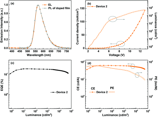 | ||
| Fig. 4 EL performance of Device 2: (a) comparison between the EL and the PL of the BPyPmIr doped TCTA film, (b) J–V–L curves, (c) EQE vs. luminance curve, and (d) CE and PE vs. luminance curves. | ||
| Device | Doping level [wt%] | V [V] | L [cd m−2] | EQEc [%] | CEc [cd A−1] | PEc [lm W−1] |
|---|---|---|---|---|---|---|
a Driving voltages (V) in the order of at a luminance of 1, 1000 and 10![[thin space (1/6-em)]](https://www.rsc.org/images/entities/char_2009.gif) 000 cd m−2.
b The maximum value of L and the voltages at which they were obtained.
c EQE, CE and PE in the order of the maximum value and at 100 and 1000 cd m−2. 000 cd m−2.
b The maximum value of L and the voltages at which they were obtained.
c EQE, CE and PE in the order of the maximum value and at 100 and 1000 cd m−2.
|
||||||
| 1 | 8 | 3.0/6.9/8.9 | 59![[thin space (1/6-em)]](https://www.rsc.org/images/entities/char_2009.gif) 409 (11.9 V) 409 (11.9 V) |
10.8/10.4/10.0 | 36.1/34.9/33.5 | 24.7/18.3/15.1 |
| 2 | 10 | 2.4/5.5/8.7 | 54![[thin space (1/6-em)]](https://www.rsc.org/images/entities/char_2009.gif) 378 (12.9 V) 378 (12.9 V) |
18.7/18.3/17.8 | 62.8/61.7/59.9 | 60.9/43.3/34.3 |
| 3 | 12 | 2.6/7.5/9.9 | 40![[thin space (1/6-em)]](https://www.rsc.org/images/entities/char_2009.gif) 059 (13.6 V) 059 (13.6 V) |
9.9/9.5/8.8 | 33.3/32.0/29.7 | 28.5/17.7/12.4 |
| Emitter | Maximum device performance | At 1000 cd m−2 | Ref. | ||||
|---|---|---|---|---|---|---|---|
| EQE [%] | CE [cd A−1] | PE [lm W−1] | EQE [%] | CE [cd A−1] | PE [lm W−1] | ||
| a Not reported. b Collected at 100 cd m−2. | |||||||
| BPyPmIr | 18.7 | 62.8 | 60.9 | 17.8 | 59.9 | 34.3 | This work |
| Ir–G1 | 16.4 | 40.9 | 39.5 | 14.6 | 35.7 | 31.6 | 31 |
| 1 | 19.2 | 40.1 | —a | —a | —a | —a | 32 |
| Ir(TPABPBI)2(acac) | 15.0 | 30.0 | 6.80 | —a | 29.4 | 6.12 | 33 |
| (Et-Cz-BTz)2Ir(EO2-pic) | 19 | 60 | —a | —a | —a | —a | 34 |
| Y1 | 7.55 | 15.1 | —a | —a | —a | —a | 35 |
| 2-FBNO | 18.9b | 65.7b | 64.4b | 18.5 | 64.7 | 52.3 | 36 |
| FCF3BNO | 21.1b | 76.5b | 49.0b | 22.7 | 82.5 | 49.2 | 37 |
| m-LIrpic | 17.1 | 43.9 | 23.0 | 14.8 | 38.0 | 16.5 | 38 |
Fluoride ion sensing properties
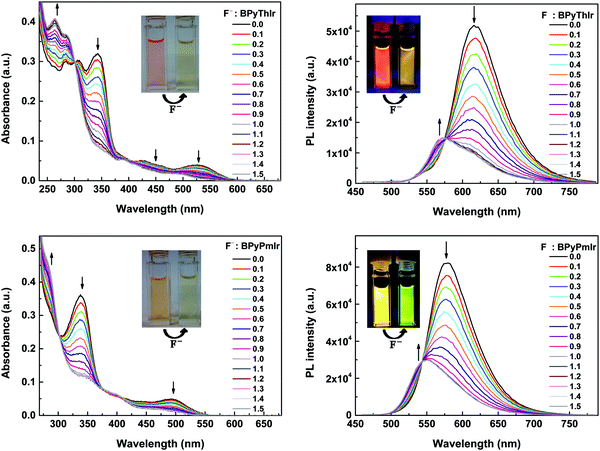
Upon adding (n-Bu)4NF, the absorption and emission spectra of BPyPmIr and BPyThIr exhibited significant changes (Fig. 5), indicating the strong B–F interactions between the B(Mes)2 moieties and F− ions. The mass spectrometry (MS) investigation also proved the adduction reactions of BPyPmIr and BPyThIr with F− ions (see Fig. S8 in the ESI†). The absorption bands with peaks >300 nm decreased gradually concomitantly with the emergence and growth of the bands with peaks <300 nm, which were in line with the observations that the THF solutions of BPyPmIr and BPyThIr became colorless after the addition of F− ions. The blue-shifted low-energy absorption bands implied that the low energy emissions should decrease, which was clearly verified by the emission changes upon addition of n-NBu4F (Fig. 5). The electron-accepting ability of B(Mes)2 would be weakened to some extent upon binding with F− ions, leading to a significant change in the LUMO distribution, and thus the higher energy emission bands emerged and grew gradually during the addition of F− ions. At first, we used BPyThIr as the sensor to detect F− ions, and the emission color changed from red to dark orange-yellow. Considering that human eyes are more sensitive to green light, it will be much easier to differentiate the color change with the naked eye if the emission color can be changed to green. Therefore, we replaced the Th ligand with the Pm ligand to blue-shift the emission wavelength. As a result, the emission color was tuned to the highly desired green region when BPyPmIr was bound to F− ions, making BPyPmIr a much better F− ion sensor.To gain deep insight into these photophysical changes, theoretical calculations were conducted. As shown in Fig. 6a, after binding to F− ions, the resultant adducts BPyPmIr-F and BPyThIr-F showed different HOMO and LUMO distribution patterns compared with BPyPmIr and BPyThIr. Although the HOMOs of BPyPmIr-F and BPyThIr-F were composed of significant contributions from Ir(III) centers and the BPy ligand bearing F− ion (marked as BPy-F) (see Tables S3 and S4 in the ESI†), the LUMOs of BPyPmIr-F and BPyThIr-F were dominantly (>90%) located on the Pm and Th ligands, respectively. Therefore, upon addition of F− ions, the LUMO locations were gradually switched from the BPy ligands in BPyPmIr and BPyThIr to the Pm and Th ligands in BPyPmIr-F and BPyThIr-F, respectively, resulting in blue-shifts of low-energy absorptions. We also calculated the NTOs of BPyPmIr-F and BPyThIr-F to understand the emission changes. As shown in Fig. 6b, the hole orbitals of BPyPmIr-F and BPyThIr-F were mainly distributed on the Ir(III) centers, the chelated phenyl ring in the BPy-F ligand, and the Pm/Th ligand (see Table S5 in the ESI†), while the particle orbitals of BPyPmIr-F and BPyThIr-F were dominantly (∼90%) located on the Pm and Th ligands, respectively. The weights of the hole → particle transition to the T1 states of BPyPmIr-F and BPyThIr-F were nearly 100%. Clearly, the emissions of BPyPmIr-F and BPyThIr-F mainly originated from the MLCT (from the d orbital of the Ir(III) center to the π* orbital of the Pm/Th ligand) transition mixed with ππ* (from the π to π* orbitals of the Pm/Th ligand) transition. This transition behavior was also the case in (Th)2Ir(acac) and (Pm)2Ir(acac). Hence, emissions of the resultant adducts BPyPmIr-F (λem = 546 nm) and BPyThIr-F (λem = 570 nm) became close to those of (Pm)2Ir(acac) (λem = 496 nm) and (Th)2Ir(acac) (λem = 546 nm), respectively, leading to significant emission color changes.
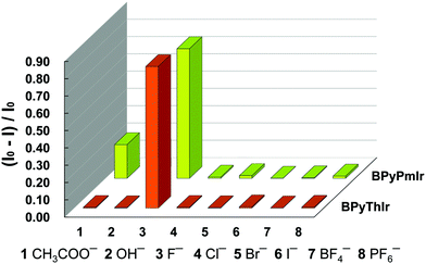
Based on the titration experiments, the Stern–Volmer constants were calculated to be 1.82 × 10⁵ M−1 and 1.65 × 10⁵ M−1 for BPyPmIr and BPyThIr, respectively, which were comparable to the values reported previously.11,27,54 However, the detection limits using BPyPmIr and BPyThIr as fluoride ion sensors were 1.55 × 10⁻⁷ M and 2.31 × 10⁻⁷ M, respectively, which were much lower than those of previously reported fluoride ion sensors,48 indicating that BPyPmIr and BPyThIr were excellent phosphorescent fluoride ion sensors with high sensitivity. The sensing properties of BPyPmIr and BPyThIr with regard to other tetrabutylammonium anion salts ((n-Bu)4NAc, (n-Bu)4NBF4, (n-Bu)4NBr, (n-Bu)4NCl, (n-Bu)4I, (n-Bu)4NOH and (n-Bu)4NPF6) were also investigated. As shown in Fig. 7, only (n-Bu)4NF could dramatically change the emission properties of BPyPmIr and BPyThIr in THF; therefore, BPyPmIr and BPyThIr exhibited outstanding selectivity to F− ions. Because of the empty pπ orbital on the boron center, boron atoms have a strong tendency to bind to F− ions, which ensures the high sensitivity to F− ions. Meanwhile, the sterically bulky B(Mes)2 can hinder the oversize anion from approaching the boron center, resulting in high selectivity to F− ions. In brief, BPyPmIr is a high performance “color-switch” sensor with outstanding sensitivity and selectivity to F− ions.
Conclusion
In summary, we designed and synthesized a triarylboron-based asymmetric Ir(III) complex (BPyPmIr) showing a very high PLQY of 0.88 in THF at room temperature. In addition, the PLQY of the TCTA film doped with this complex could be enhanced up to 0.99. Therefore, a solution-processed yellow OLED based on BPyPmIr exhibited impressive performance with the peak luminescence, EQE, CE, and PE of 54![[thin space (1/6-em)]](https://www.rsc.org/images/entities/char_2009.gif) 378 cd m−2, 18.7%, 62.8 cd A−1 and 60.9 lm W−1, respectively, and very low efficiency roll-off, which was among the best performances of reported solution-processed yellow OLEDs. Owing to the strong B–F interaction between the B(Mes)2 moiety and F− ions, this complex was used as a high performance “color-switch” sensor for F− ions with excellent sensitivity and selectivity and distinct emission color change upon addition of F− ions. These results clearly demonstrate the bifunctional character of triarylboron-based asymmetric Ir(III) complexes for applications in high performance OLEDs and F− ion sensors. More importantly, by intentionally incorporating functional groups into asymmetric Ir(III) complexes, this work provides a new and effective way to develop multifuctional materials. For example, if an aldehyde group is introduced into the Pm ligand in BPyPmIr, which is quite easy to do, the resultant Ir(III) complex is highly expected to possess one more ability to detect hydrogen sulfite because of the aldehyde–hydrogen sulfite addition reaction.55
378 cd m−2, 18.7%, 62.8 cd A−1 and 60.9 lm W−1, respectively, and very low efficiency roll-off, which was among the best performances of reported solution-processed yellow OLEDs. Owing to the strong B–F interaction between the B(Mes)2 moiety and F− ions, this complex was used as a high performance “color-switch” sensor for F− ions with excellent sensitivity and selectivity and distinct emission color change upon addition of F− ions. These results clearly demonstrate the bifunctional character of triarylboron-based asymmetric Ir(III) complexes for applications in high performance OLEDs and F− ion sensors. More importantly, by intentionally incorporating functional groups into asymmetric Ir(III) complexes, this work provides a new and effective way to develop multifuctional materials. For example, if an aldehyde group is introduced into the Pm ligand in BPyPmIr, which is quite easy to do, the resultant Ir(III) complex is highly expected to possess one more ability to detect hydrogen sulfite because of the aldehyde–hydrogen sulfite addition reaction.55
Conflicts of interest
There are no conflicts to declare.Acknowledgements
This work was financially supported by the National Natural Science Foundation of China (Grant No. 21602170, 51803163, 21572176, and 21875179), the Natural Science Foundation of Shaanxi Province (Grant No. 2016JQ2011), the China Postdoctoral Science Foundation (Grant No. 2015M580831 and 2016M600778), the Shaanxi Province Postdoctoral Science Foundation (Grant No. 2017BSHYDZZ02 and 2017BSHEDZZ03), the Fundamental Research Funds for the Central Universities (Grant No. xjj2016061, xjj2017099, and cxtd2015003). The characterization assistance from the Instrument Analysis Center of Xi’an Jiaotong University was also acknowledged. W.-Y. W. thanks The Hong Kong Polytechnic University (1-ZE1C) and acknowledges the Endowment Fund from Ms Clarea Au (847S) for financial support.References
- S. Lamansky, P. Djurovich, D. Murphy, F. Abdel-Razzaq, H. E. Lee, C. Adachi, P. E. Burrows, S. R. Forrest and M. E. Thompson, J. Am. Chem. Soc., 2001, 123, 4304–4312 CrossRef CAS PubMed.
- C. Fan and C. Yang, Chem. Soc. Rev., 2014, 43, 6439–6469 RSC.
- X. Yang, G. Zhou and W.-Y. Wong, Chem. Soc. Rev., 2015, 44, 8484–8575 RSC.
- Y. Chi, T.-K. Chang, P. Ganesan and P. Rajakannu, Coord. Chem. Rev., 2017, 346, 91–100 CrossRef CAS.
- F. Zhao and D. Ma, Mater. Chem. Front., 2017, 1, 1933–1950 RSC.
- T. B. Fleetham, Z. X. Wang and J. Li, Inorg. Chem., 2013, 52, 7338–7343 CrossRef CAS PubMed.
- J. Wang, T. Wang, D. Cao, X. Zhao, J. Liu, M. Zhuo, B. Mi and Z. Gao, Org. Electron., 2015, 23, 11–16 CrossRef CAS.
- Y. You and W. Nam, Chem. Soc. Rev., 2012, 41, 7061–7084 RSC.
- K. K. W. Lo, B. T. N. Chan, H. W. Liu, K. Y. Zhang, S. P. Y. Li and T. S. M. Tang, Chem. Commun., 2013, 49, 4271–4273 RSC.
- Y. You, Curr. Opin. Chem. Biol., 2013, 17, 699–707 CrossRef CAS PubMed.
- Y. M. You and S. Y. Park, Adv. Mater., 2008, 20, 3820–3826 CrossRef CAS.
- W. J. Xu, S. J. Liu, X. Y. Zhao, S. Sun, S. Cheng, T. C. Ma, H. B. Sun, Q. A. Zhao and W. Huang, Chem. – Eur. J., 2010, 16, 7125–7133 CrossRef CAS PubMed.
- F. N. Lu, M. Yamamura and T. Nabeshima, Dalton Trans., 2013, 42, 12093–12100 RSC.
- A. B. Tamayo, B. D. Alleyne, P. I. Djurovich, S. Lamansky, I. Tsyba, N. N. Ho, R. Bau and M. E. Thompson, J. Am. Chem. Soc., 2003, 125, 7377–7387 CrossRef CAS PubMed.
- X. Xu, H. Guo, J. Zhao, B. Liu, X. Yang, G. Zhou and Z. Wu, Chem. Mater., 2016, 28, 8556–8569 CrossRef CAS.
- Z. Feng, D. Wang, X. Yang, D. Jin, D. Zhong, B. Liu, G. Zhou, M. Ma and Z. Wu, Inorg. Chem., 2018, 57, 11027–11043 CrossRef CAS PubMed.
- X. Yang, H. Guo, B. Liu, J. Zhao, G. Zhou, Z. Wu and W.-Y. Wong, Adv. Sci., 2018, 5, 1701067 CrossRef PubMed.
- Ł. Górski, A. Matusevich, P. Parzuchowski, I. Łuciuk and E. Malinowska, Anal. Chim. Acta, 2010, 665, 39–46 CrossRef PubMed.
- P. Thiampanya, N. Muangsin and B. Pulpoka, Org. Lett., 2012, 14, 4050–4053 CrossRef CAS PubMed.
- M. Melaimi and F. P. Gabbai, J. Am. Chem. Soc., 2005, 127, 9680–9681 CrossRef CAS PubMed.
- F. Cheng, E. M. Bonder and F. Jakle, J. Am. Chem. Soc., 2013, 135, 17286–17289 CrossRef CAS PubMed.
- Z. M. Hudson and S. Wang, Acc. Chem. Res., 2009, 42, 1584–1596 CrossRef CAS PubMed.
- C. R. Wade, A. E. Broomsgrove, S. Aldridge and F. P. Gabbaï, Chem. Rev., 2010, 110, 3958–3984 CrossRef CAS PubMed.
- T. W. Hudnall and F. P. Gabbai, J. Am. Chem. Soc., 2007, 129, 11978–11986 CrossRef CAS PubMed.
- K. Parab, K. Venkatasubbaiah and F. Jakle, J. Am. Chem. Soc., 2006, 128, 12879–12885 CrossRef CAS PubMed.
- Y. H. Lee, N. V. Nghia, M. J. Go, J. Lee, S. U. Lee and M. H. Lee, Organometallics, 2014, 33, 753–762 CrossRef CAS.
- S. Sole and F. P. Gabbai, Chem. Commun., 2004, 1284–1285 RSC.
- X. Y. Liu, D. R. Bai and S. N. Wang, Angew. Chem., Int. Ed., 2006, 45, 5475–5478 CrossRef CAS PubMed.
- Q. Li, M. Peng, H. Li, C. Zhong, L. Zhang, X. Cheng, X. Peng, Q. Wang, J. Qin and Z. Li, Org. Lett., 2012, 14, 2094–2097 CrossRef CAS PubMed.
- J. Ding, H. Li, C. Wang, J. Yang, Y. Xie, Q. Peng, Q. Li and Z. Li, ACS Appl. Mater. Interfaces, 2015, 7, 11369–11376 CrossRef CAS PubMed.
- M. R. Zhu, J. H. Zou, X. He, C. L. Yang, H. B. Wu, C. Zhong, J. G. Qin and Y. Cao, Chem. Mater., 2012, 24, 174–180 CrossRef CAS.
- L. Fu, M. Pan, Y. H. Li, H. B. Wu, H. P. Wang, C. Yan, K. Li, S. C. Wei, Z. Wang and C. Y. Su, J. Mater. Chem., 2012, 22, 22496–22500 RSC.
- X. Ouyang, D. Chen, S. Zeng, X. Zhang, S. Su and Z. Ge, J. Mater. Chem., 2012, 22, 23005–23011 RSC.
- T. Giridhar, W. Cho, Y.-H. Kim, T.-H. Han, T.-W. Lee and S.-H. Jin, J. Mater. Chem. C, 2014, 2, 9398–9405 RSC.
- A. Liang, G. Huang, S. Dong, X. Zheng, J. Zhu, Z. Wang, W. Wu, J. Zhang and F. Huang, J. Mater. Chem. C, 2016, 4, 6626–6633 RSC.
- J.-H. Jou, Y.-X. Lin, S.-H. Peng, C.-J. Li, Y.-M. Yang, C.-L. Chin, J.-J. Shyue, S.-S. Sun, M. Lee, C.-T. Chen, M.-C. Liu, C.-C. Chen, G.-Y. Chen, J.-H. Wu, C.-H. Li, C.-F. Sung, M.-J. Lee and J.-P. Hu, Adv. Funct. Mater., 2014, 24, 555–562 CrossRef CAS.
- J.-H. Jou, S.-C. Fu, C.-C. An, J.-J. Shyue, C.-L. Chin and Z.-K. He, J. Mater. Chem. C, 2017, 5, 5478–5486 RSC.
- G. Sarada, J. Yoon, W. Cho, M. Cho, D. W. Cho, S. O. Kang, Y. Nam, J. Y. Lee and S.-H. Jin, J. Mater. Chem. C, 2016, 4, 113–120 RSC.
- S. A. Moore, D. L. Davies, M. M. Karim, J. K. Nagle, M. O. Wolf and B. O. Patrick, Dalton Trans., 2013, 42, 12354–12363 RSC.
- T. Giridhar, W. Cho, J. Park, J. S. Park, Y. S. Gal, S. Kang, J. Y. Lee and S. H. Jin, J. Mater. Chem. C, 2013, 1, 2368–2378 RSC.
- A. Tsuboyama, H. Iwawaki, M. Furugori, T. Mukaide, J. Kamatani, S. Igawa, T. Moriyama, S. Miura, T. Takiguchi, S. Okada, M. Hoshino and K. Ueno, J. Am. Chem. Soc., 2003, 125, 12971–12979 CrossRef CAS PubMed.
- J. M. Fernandez-Hernandez, J. I. Beltran, V. Lemaur, M. D. Galvez-Lopez, C. H. Chien, F. Polo, E. Orselli, R. Frohlich, J. Cornil and L. De Cola, Inorg. Chem., 2013, 52, 1812–1824 CrossRef CAS PubMed.
- L. C. Chen, J. Q. Ding, Y. X. Cheng, Z. Y. Xie, L. X. Wang, X. B. Jing and F. S. Wang, Chem. – Asian J., 2011, 6, 1372–1380 CrossRef CAS PubMed.
- S. J. Lee, J. S. Park, M. Song, I. A. Shin, Y. I. Kim, J. W. Lee, J. W. Kang, Y. S. Gal, S. Kang, J. Y. Lee, S. H. Jung, H. S. Kim, M. Y. Chae and S. H. Jin, Adv. Funct. Mater., 2009, 19, 2205–2212 CrossRef CAS.
- S. Lamansky, P. Djurovich, D. Murphy, F. Abdel-Razzaq, R. Kwong, I. Tsyba, M. Bortz, B. Mui, R. Bau and M. E. Thompson, Inorg. Chem., 2001, 40, 1704–1711 CrossRef CAS PubMed.
- C. Yao, B. Jiao, X. Yang, X. Xu, J. Dang, G. Zhou, Z. Wu, X. Lv, Y. Zeng and W. Y. Wong, Eur. J. Inorg. Chem., 2013, 4754–4763 CrossRef CAS.
- G. Ge, J. He, H. Guo, F. Wang and D. Zou, J. Organomet. Chem., 2009, 694, 3050–3057 CrossRef CAS.
- X. Yang, Z. Huang, C.-L. Ho, G. Zhou, D. R. Whang, C. Yao, X. Xu, S. Y. Park, C.-H. Chui and W.-Y. Wong, RSC Adv., 2013, 3, 6553–6563 RSC.
- M. K. Nazeeruddin, R. Humphry-Baker, D. Berner, S. Rivier, L. Zuppiroli and M. Graetzel, J. Am. Chem. Soc., 2003, 125, 8790–8797 CrossRef CAS.
- E. Baranoff, J. H. Yum, M. Graetzel and M. K. Nazeeruddin, J. Organomet. Chem., 2009, 694, 2661–2670 CrossRef CAS.
- D. D. Wang, Y. Wu, H. Dong, Z. X. Qin, D. Zhao, Y. Yu, G. J. Zhou, B. Jiao, Z. X. Wu, M. Gao and G. Wang, Org. Electron., 2013, 14, 3297–3305 CrossRef CAS.
- G. J. Zhou, C. L. Ho, W. Y. Wong, Q. Wang, D. G. Ma, L. X. Wang, Z. Y. Lin, T. B. Marder and A. Beeby, Adv. Funct. Mater., 2008, 18, 499–511 CrossRef CAS.
- L. J. Deng, T. Zhang, R. J. Wang and J. Y. Li, J. Mater. Chem., 2012, 22, 15910–15918 RSC.
- Y. L. Rao and S. N. Wang, Inorg. Chem., 2009, 48, 7698–7713 CrossRef CAS PubMed.
- X. Cheng, H. Jia, J. Feng, J. Qin and Z. Li, J. Mater. Chem. B, 2013, 1, 4110–4114 RSC.
Footnote |
| † Electronic supplementary information (ESI) available. See DOI: 10.1039/c8qm00548f |
| This journal is © the Partner Organisations 2019 |

