Side chain engineering on dithieno[3,2-b:2,3-d]pyrrol fused electron acceptors for efficient organic solar cells†
Haohao
Feng‡
a,
Xin
Song‡
b,
Ming
Zhang
c,
Jiangsheng
Yu
d,
Zhuohan
Zhang
a,
Renyong
Geng
b,
Linqiang
Yang
a,
Feng
Liu
*c,
Derya
Baran
*b and
Weihua
Tang
 *a
*a
aSchool of Chemical Engineering, Nanjing University of Science and Technology, Nanjing 210094, P. R. China. E-mail: whtang@njust.edu.cn
bKAUST Solar Center (KSC), King Abdullah University of Science and Technology (KAUST), Thuwal 23955-6900, Saudi Arabia. E-mail: derya.baran@kaust.edu.sa
cDepartment of Physics and Astronomy, Collaborative Innovation Center of IFSA, Shanghai Jiao Tong University, Shanghai 200240, China. E-mail: fengliu82@sjtu.edu.cn
dMIIT Key Laboratory of Advanced Solid Laser, Nanjing University of Science and Technology, Nanjing 210094, P. R. China
First published on 5th March 2019
Abstract
Two novel dithieno[3,2-b:2,3-d]pyrrol fused electron acceptors (FREAs) with branched alkyl side-chains have been developed. With 2-ethylhexyl and 2-butyloctyl introduced on the N-position of the pyrrol unit, the sidechain engineered acceptors (INPIC-EH and INPIC-BO) were evaluated for organic solar cells (OSCs) by comparison with our reference INPIC-4F bearing a linear octyl chain. The optoelectronic properties of the FREAs and their bulk-heterojunction (BHJ) with a PBDB-T donor for OSCs are systematically studied. All FREAs exhibit similar absorption spectra and energy levels. Notably, the charge dissociation process, charge mobility, and morphology of the BHJ films make a distinct difference. Consequently, the OSCs constructed with INPIC-EH and INPIC-BO delivered a power conversion efficiency (PCE) of 11.9% and 11.2%, lower than that of INPIC-4F devices (13.1%). The lower short-circuit current density (JSC) and fill factor (FF) of INPIC-EH and INPIC-OB based devices are attributed to unfavorable morphology of the active layers and more bimolecular recombination and unbalanced charge transport. Our investigation demonstrates that side-chain engineering on FREAs has a great impact on the morphology of blends and thus the photovoltaic properties of their OSCs.
1 Introduction
Solution-processed organic solar cells (OSCs) based on a bulk-heterojunction (BHJ) structure have attracted much attention due to their unique advantages such as low cost, light weight and mechanical flexibility.1–7 Typically, the active layer as a BHJ blend of an electron donor and acceptor is one of the most critical considerations in OSCs. The early exploration of efficient OSCs centred on the design of new donors (polymers or small molecules) and their device engineering with fullerene based acceptors.8 However, the inherent drawbacks of fullerene acceptors such as limited absorption range in the solar spectrum and low stability under continuous solar irradiance have significantly constrained the performance of OSCs. In fact, the power conversion efficiencies (PCEs) of fullerene-based OSCs have not surpassed 13% despite enormous device optimization. To overcome these limitations, fused-ring electron acceptors (FREAs) have been explored, which enable OSC PCEs exceeding 14% in single junction9–13 and over 17% in tandem devices.14 The merits of FREAs for such rapid progress mainly stem from their versatile structure and energy level modification, including an electron-withdrawing terminal block, ladder-type electron-donating (ED) core and outstretched sidechains, which feature fine regulation of their absorption spectra, the frontier orbital levels and the molecular ordering behaviours. For the ED cores, the universal strategy for construction of more electron-rich fused-ring blocks is either introducing donating side-chains on ED cores or extending ED cores with aromatic heterocycles. Recently, by inserting pyrrole rings into the IDTT core, our group developed a new fused-ring ED core, namely, 5,5,12,12-tetrakis(4-hexylphenyl)-indacenobis(dithieno[3,2-b:2′,3′-d]pyrrol) (INP),15,16 which shows a stronger ED capability and more conjugated molecular framework in comparison to the IDTT core.17Besides developing new fused ED blocks, the screening of suitable sidechains on these blocks is crucial to achieve high performance FREAs.18–20 In particular, the crystallinity, absorption range and solubility of FREAs can be carefully modulated by sidechain length and degree of branching, since they have great impact on the intermolecular packing, blend morphology, and thus photovoltaic performance of their OSCs. For our recently developed INPIC, the crystallization dynamics study revealed that INPIC-4F had a large tendency to form polycrystalline spherulites exhibiting faster molecular ordering than polymer donor like PBDB-T, resulting in large phase separation and low device performance (below 10%).21 To fine-tune the crystallization behaviour of NFAs for synchronization with the polymer donor, sidechain-engineering on INPIC-4F by extending or branching alkyl chains on the N-position of the pyrrole unit is important to achieve good phase separation and device performance in OSCs. However, studies on incorporating multiple sidechains in FREAs have been reported less often in the literature. Therefore, it is urgent to conduct systematic studies for high-efficiency FREAs on the length and degree of branching in sidechains, so as to explore the impact of sidechains on their optoelectronic properties, molecular packing, blend morphology and photovoltaic performance.
To address the challenges discussed above, we have designed and synthesized two novel INP-based FREAs with branched 2-ethylhexyl or 2-butyl-1-octyl alkyl chains, namely, INPIC-EH and INPIC-BO. A careful comparison study was conducted with the start-of-the-art acceptor INPIC-4F bearing an n-octyl linear sidechain, since the INP core is one of the best cores for such study due to its easy functionalization on the N-atom of the pyrrole unit.15 Fluorinated 2-(2,3-dihydro-3-oxo-1H-inden-1-ylidene) propanedinitrile (IC) as the electron-withdrawing group can promote intermolecular interaction and leads to broad and strong absorption throughout the visible and near-infrared region. After coupling INP cores bearing different sidechains with an IC endgroup, we can easily manipulate the charge transport, molecular ordering, and photovoltaic performance of the resultant FREAs. Indeed, the absorption range and energy level for INP series FREAs show subtle differences when changing the sidechains from linear to branched properties. More importantly, due to the enhanced π–π stacking and crystallinity, INPIC-4F with a C8 linear sidechain exhibited notable improvement of charge transport in comparison to INPIC-EH and INPIC-BO with branched sidechains. The widely used polymer PBDB-T was chosen as a donor due to its complementary absorption with three FREAs. The optimal INPIC-4F based devices achieved the champion PCE of 13.1%, with an open-circuit voltage (VOC) of 0.85 V, a short-circuit current (JSC) of 21.9 mA cm−2, and a FF of 69.8%. When the linear octyl group changes to a branched alkyl side chain, INPIC-EH or INPIC-BO based blend films exhibit coarser morphology with a larger domain size, leading to severe biomolecular recombination and unbalanced charge transport. Consequently, the decreased JSCs and FFs of INPIC-EH and INPIC-OB based devices result in lower PCEs of 11.9% and 11.2%, respectively.
2 Results and discussion
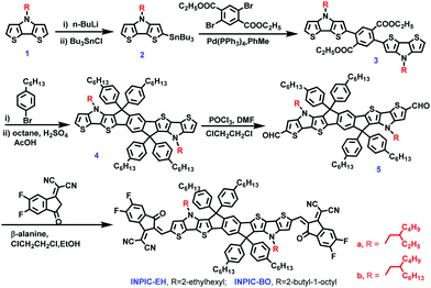
As shown in Scheme 1, INPIC-EH and INPIC-BO were synthesized via Knoevenagel condensation between 2F-IC and the corresponding INP cores with varied N-sidechains on the pyrrol unit, with the detailed synthesis procedure provided in Scheme S1 (ESI†). The reference acceptor INPIC-4F was synthesized according to our previous report.15 Their chemical structures were carefully characterized using 1H NMR, 13C NMR and MALDI-TOF MS (Fig. S1–S5 in the ESI†). All FREAs are well soluble in common solvents, including chloroform and chlorobenzene (CB) at room temperature, which affords good solution processability for OSCs. Thermo-gravimetric analysis (TGA) was performed to investigate the thermal properties of the three FREAs, with TGA traces plotted in Fig. S6a (ESI†). All FREAs exhibit satisfactory thermal stability, with a high decomposition temperature (Td, 5% weight-loss) found for INPIC-4F (377 °C), INPIC-EH (365 °C) and INPIC-BO (358 °C), respectively (Table 1).| FREA | λ solmax [nm] | λ filmmax [nm] | λ filmonset [nm] | E g [eV] | HOMOb [eV] | LUMOb [eV] | E g [eV] | T d [°C] |
|---|---|---|---|---|---|---|---|---|
| a The bandgap was obtained from the onset of UV-Vis absorption for each film. b The LUMO and HOMO energy levels were measured by CV. c The bandgap was calculated using the following equation: Eg = ELUMO − EHOMO. | ||||||||
| INPIC-4F | 769 | 821 | 892 | 1.39 | −5.42 | −3.95 | 1.47 | 377 |
| INPIC-EH | 773 | 814 | 891 | 1.39 | −5.48 | −3.99 | 1.49 | 365 |
| INPIC-BO | 776 | 824 | 899 | 1.38 | −5.47 | −3.97 | 1.50 | 358 |
The UV-Vis absorption spectra of three FREAs in chloroform solutions and thin films are plotted in Fig. S6b (ESI†) and Fig. 1a, respectively, with detailed optical data summarized in Table 1. Three acceptors possess very similar absorption profiles in chloroform solution with strong absorption in the range of 600–800 nm. As shown in Fig. S6c (ESI†), in chloroform solutions, INPIC-4F exhibits the highest maximum molar extinction coefficient of 3.51 × 10⁵ M−1 cm−1 at 770 nm among the three FREAs (3.26 × 10⁵ M−1 cm−1 for INPIC-EH, and 3.34 × 10⁵ M−1 cm−1 for INPIC-BO), which might be attributed to the stronger intramolecular interactions in INPIC-4F with less steric hindrance from linear octyl chains. In a film state, these INP-based FREAs exhibit clearly red-shifted and broadened absorption spectra compared to their solutions, suggesting a relatively strong propensity to form ordered aggregates in thin films. The maximum absorption peak for INPIC-4F (821 nm), INPIC-EH (814 nm) and INPIC-BO (824 nm) films exhibits an obvious red-shift of 52 nm, 41 nm and 48 nm, respectively, in comparison to their solutions. The optical bandgap (Eoptg) deduced from the absorption edges (λedge) is 1.39 eV, 1.39 eV and 1.38 eV for INPIC-4F, INPIC-EH and INPIC-BO, respectively.
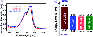 | ||
| Fig. 1 (a) Normalized UV-Vis absorption spectra of three INP-based FREAs in thin films; (b) energy level diagram of PBDB-T and the FREAs. | ||
To evaluate the electrochemical properties of FREAs, cyclic voltammetry (CV) was performed with their ultrathin films on a carbon working electrode. All three FREAs exhibit highly irreversible reduction and oxidation waves (Fig. S6d, ESI†), as observed for FREAS (ca. S(TPA-DPP), DBS-2DPP and IHIC) in the literature.22–24 This behaviour can be explained by “charge-trapping” phenomena,25 which may be attributed to the irreversible chemical alternations of the A–D–A conjugation chain with insertion of reversible redox states of quinone type for thiophene-based semiconductors. The highest occupied molecular orbital (HOMO) and the lowest unoccupied molecular orbital (LUMO) energy levels were determined from the redox potentials.15 The detailed CV data are listed in Table 1. The onset oxidation potential of INPIC-4F, INPIC-EH and INPIC-BO is observed at 1.02 V, 1.08 V and 1.07 V versus Ag/AgCl, corresponding to a HOMO level of −5.42, −5.48 and −5.47 eV, respectively. The LUMO level is calculated to be −3.95, −3.99 and −3.97 eV for INPIC-4F, INPIC-EH and INPIC-BO, respectively, according to their onset reduction potentials.15 Three FREAs show similar HOMO and LUMO, indicating almost negligible impact of sidechains on the INP core on the energy levels of the resultant FREAs.
In order to investigate the impact of FREA side-chain engineering on their photovoltaic performance, we fabricated the BHJ binary OSCs by blending the PBDB-T polymer donor with the sidechain-varied FREAs as active layers. The devices adopted a configuration of ITO/ZnO/Active layer/MoO3/Ag. The device fabrication procedure and characterization can be found in the ESI.† The characteristic current density–voltage (J–V) curves are shown in Fig. 2a, and the corresponding photovoltaic parameters of the devices are listed in Table 2. Three FREA-based best-performing OSCs were achieved with a D/A weight ratio of 1![[thin space (1/6-em)]](https://www.rsc.org/images/entities/char_2009.gif) :
:![[thin space (1/6-em)]](https://www.rsc.org/images/entities/char_2009.gif) 1 (total concentration of 20 mg mL−1) and processed from CB solutions with 0.5% 1,8-diiodooctane (DIO) as the additive. Under optimal device fabrication conditions, INPIC-4F based OSCs delivered the highest PCE of 13.1% with a VOC of 0.85 V, a short-circuit current (JSC) of 21.9 mA cm−2, and a FF of 69.8%. In contrast, the best-performing device based on INPIC-EH exhibited a PCE of 11.9% with a VOC of 0.84 V, a JSC of 20.7 mA cm−2, and a FF of 68.4%. And the best-performing device based on INPIC-BO exhibited a PCE of 11.2% with a VOC of 0.84 V, a JSC of 20.0 mA cm−2, and a FF of 66.8%. The three FREA-based solar cells showed almost the same VOC of 0.84–0.85 eV, due to their similar LUMO energy levels. With the sidechain changed from a linear alkyl chain to branched alkyl chains on the INP unit, the device performance gradually reduced. The corresponding EQEs of INPIC-4F, INPIC-EH and INPIC-BO based OSCs were also characterized to evaluate the photoresponse of the blends (Fig. 2b). The EQE curves exhibited a broad photocurrent response in the range of 300–900 nm for all devices. In particular, for the PBDB-T:INPIC-4F device, the EQE reached over 60% from 480 to 855 nm with a maximum value of 76% at 650 nm, indicating an efficient photoelectron conversion process in the active layer. In contrast, the EQE exceeding 60% from 500 to 840 nm with a peak of 72% at 650 nm is observed for INPIC-EH based devices, while EQE over 60% in the region of 500–820 nm with a peak of 69% at 650 nm is found for PBDB-T:INPIC-BO based OSCs. The JSC value calculated by integrating EQE data with the AM 1.5G solar spectrum is 20.9, 19.8 and 19.3 mA cm−2 for INPIC-4F, INPIC-EH and INPIC-BO based devices, respectively. Notably, the integrated current density values extracted from the EQE spectra agree well with those from J–V curves in Fig. 2a, and the mismatches are less than 5%.
1 (total concentration of 20 mg mL−1) and processed from CB solutions with 0.5% 1,8-diiodooctane (DIO) as the additive. Under optimal device fabrication conditions, INPIC-4F based OSCs delivered the highest PCE of 13.1% with a VOC of 0.85 V, a short-circuit current (JSC) of 21.9 mA cm−2, and a FF of 69.8%. In contrast, the best-performing device based on INPIC-EH exhibited a PCE of 11.9% with a VOC of 0.84 V, a JSC of 20.7 mA cm−2, and a FF of 68.4%. And the best-performing device based on INPIC-BO exhibited a PCE of 11.2% with a VOC of 0.84 V, a JSC of 20.0 mA cm−2, and a FF of 66.8%. The three FREA-based solar cells showed almost the same VOC of 0.84–0.85 eV, due to their similar LUMO energy levels. With the sidechain changed from a linear alkyl chain to branched alkyl chains on the INP unit, the device performance gradually reduced. The corresponding EQEs of INPIC-4F, INPIC-EH and INPIC-BO based OSCs were also characterized to evaluate the photoresponse of the blends (Fig. 2b). The EQE curves exhibited a broad photocurrent response in the range of 300–900 nm for all devices. In particular, for the PBDB-T:INPIC-4F device, the EQE reached over 60% from 480 to 855 nm with a maximum value of 76% at 650 nm, indicating an efficient photoelectron conversion process in the active layer. In contrast, the EQE exceeding 60% from 500 to 840 nm with a peak of 72% at 650 nm is observed for INPIC-EH based devices, while EQE over 60% in the region of 500–820 nm with a peak of 69% at 650 nm is found for PBDB-T:INPIC-BO based OSCs. The JSC value calculated by integrating EQE data with the AM 1.5G solar spectrum is 20.9, 19.8 and 19.3 mA cm−2 for INPIC-4F, INPIC-EH and INPIC-BO based devices, respectively. Notably, the integrated current density values extracted from the EQE spectra agree well with those from J–V curves in Fig. 2a, and the mismatches are less than 5%.
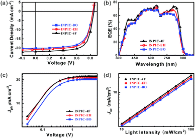 | ||
| Fig. 2 (a) J–V curves under AM 1.5 G illumination, (b) EQE plots, and (c) Jphversus Veff, and (d) JSCversus light intensity of the designed devices. | ||
| Acceptor | V OC (V) | J SC (mA cm−2) | Cal. JSC (mA cm−2) | FF (%) | PCE (%) | PCEave (%) |
|---|---|---|---|---|---|---|
| PCEave refers to average PCE values obtained from 20 devices. | ||||||
| INPIC-4F | 852 | 21.9 | 20.9 | 69.8 | 13.1 | 12.7 ± 0.4 |
| INPIC-EH | 837 | 20.7 | 19.8 | 68.4 | 11.9 | 11.7 ± 0.2 |
| INPIC-BO | 839 | 20.0 | 19.3 | 66.8 | 11.2 | 10.9 ± 0.3 |
Compared to INPIC-4F, INPIC-EH and INPIC-BO based devices exhibited decreased JSC and FF values (Fig. 2a), which is mainly attributed to the processes of exciton dissociation and charge collection. To understand the exciton dissociation and charge collection efficiencies of the three FREA-based OSCs, photocurrent density (Jph) as a function of effective voltage (Veff) is shown in Fig. 2c. Jph is defined as Jph = JL − JD, where JL and JD are the current densities under illumination and in the dark, respectively. Veff is defined as Veff = V0 − V, where V0 is the voltage at which the photocurrent is zero and V is the applied voltage.26 We can judge the overall exciton dissociation efficiency and charge collection efficiency according to the Jph/Jsat ratio.27 Under short-circuit conditions, the Jph/Jsat was found to be 97.3%, 96.8% and 94.2% for INPIC-4F, INPIC-EH and INPIC-BO based devices, indicating a much higher exciton dissociation efficiency for the INPIC-4F based device. According to the equation: Jsat = qGmaxL, where q is the electronic charge and L is the active layer thickness,28 we can also estimate the maximum generation rate of free charge carriers (Gmax). The Gmax was estimated to be 2.03 × 10²², 1.92 × 10²² and 1.45 × 1022 cm−3 s−1 for the INPIC-4F, INPIC-EH and INPIC-BO based OSCs, respectively, confirming the best photon-to-current conversion for PBDB-T:INPIC-4F solar cells.29
To obtain better understanding of charge recombination in OSCs, JSC values under different light intensities (P) were measured. In principle, under short-circuit conditions, the relationship between JSC and P can be described by the formula JSC ∝ Pα, where the power-law exponent (α) reflects the bimolecular recombination degree. In general, α = 1 is observed for solar cells not limited by bimolecular recombination, whereas α < 1 suggests bimolecular recombination.30–32 As displayed in Fig. 2d, the fitted α values are 0.969 and 0.961 for the device based on PBDB-T:INPIC-EH and PBDB-T:INPIC-BO, while the device based on PBDB-T:INPIC-4F showed a larger α value of 0.981. The highest α value for the INPIC-4F based OSCs suggests less charge recombination in the active layer, while more bimolecular recombination occurs in INPIC-EH and INPIC-BO based devices. The decreased bimolecular recombination combined with increased exciton dissociation partially explains the higher JSC and FF values of PBDB-T:INPIC-4F based OSCs.33
In addition to the exciton dissociation and charge collection, charge carrier mobility is another important factor that affects the JSC and FF of OSCs. Herein, the electron and hole mobilities of the three blend films were measured by the space charge limited current (SCLC) method, and the characteristic curves are plotted in Fig. 3. The structure of the hole-only device is ITO/PEDOT:PSS/PBDB-T:acceptor/MoOX/Ag and the structure of the electron-only device is ITO/ZnO/PBDB-T:acceptor/Ca/Al. The hole mobility (μh) of INPIC-4F, INPIC-EH and INPIC-BO based blend films is calculated as 2.64 × 10⁻⁴, 2.21 × 10⁻⁴ and 2.06 × 10⁻⁴ cm2 V−1 S−1 (Table S1, ESI†), respectively, implying that the hole transport ability is comparable for these three blends. The electron mobility (μe) of INPIC-4F is 2.64 × 10⁻⁴ cm2 V−1 S−1, which is higher than that of INPIC-EH (1.92 × 10⁻⁴ cm2 V−1 S−1) and INPIC-BO (8.60 × 10⁻⁵ cm2 V−1 S−1) based blend films. The μh/μe ratio is thus calculated to be 1.00, 1.15 and 2.40, respectively, for INPIC-4F, INPIC-EH and INPIC-BO based blend films. The lower charge transport ability and unbalanced mobility for INPIC-EH and INPIC-BO based blend films could be responsible for the decrease of JSC and FF in their OSCs.34,35
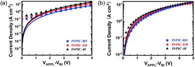 | ||
| Fig. 3 (a) Blend film hole mobility plots from SCLC measurement; (b) blend film electron mobility plots from SCLC measurement. | ||
The blend morphologies were characterized using transmission electron microscopy (TEM) and atomic force microscopy (AFM). As observed in Fig. 4, the PBDB-T:INPIC-OB film exhibits obvious phase separation with larger domain size, while the PBDB-T:INPIC-4F and PBDB-T:INPIC-EH film both have suitable domain size without clear phase separation. Furthermore, the root-mean-square (RMS) roughness of the three blend films from the AFM images are 1.78, 2.63, and 3.34 nm for INPIC-4F, INPIC-EH and INPIC-OB, respectively. The coarse film and significant blend phase separation in the INPIC-OB based film may be the reason for the lower FF and Jsc, in comparison with INPIC-4F and INPIC-EH based films.
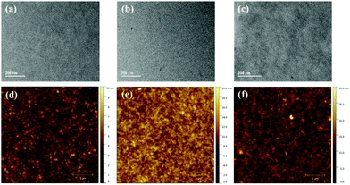 | ||
| Fig. 4 TEM and AFM images for: (a) and (d) PBDB-T:INPIC-4F; (b) and (e) PBDB-T:INPIC-EH; and (c) and (f) PBDB-T:INPIC-OB blend films. | ||
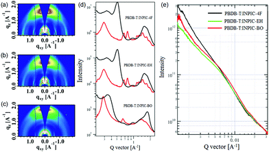
To gain more in-depth understanding of film crystallinity influenced by side-chain engineering, the grazing incidence wide-angle X-ray scattering (GIWAXS) and resonant soft X-ray scattering were investigated (Fig. 5). PBDB-T has a face-on orientation with π–π stacking at 1.76 Å−1 and a (100) diffraction peak at 0.31 Å−1. In the three acceptor neat films, π–π stacking is highly face-on and locates at 1.60 Å−1, 1.78 Å−1, and 1.80 Å−1 with corresponding π–π stacking distances (dπ–π) of 3.93 Å, 3.53 Å and 3.49 Å for INPIC-4F, INPIC-EH and INPIC-OB, respectively. For the three blend films, the crystalline feature constitutes diffraction signals from both PBDB-T and these NFAs. In particular, the PBDB-T:INPIC-OB blend film exhibits the smallest dπ–π of 3.49 Å (located at 1.81 Å−1), indicating the strongest intermolecular aggregations. We hypothesized that despite the crystallinity of INPIC-OB being higher than that of INPIC-4F and INPIC-EH, the too strong crystallinity of INPIC-OB can induce low miscibility and big domain size in the bulk-heterojunction blend film, which would further cause severe recombination and have a negative influence on the charge transport. This conclusion is consistent with the mobility we measured.
Resonant soft X-ray scattering (R-SoXS) measurements were performed to investigate the phase separation of the three blend films. As observed from Fig. 5e, the INPIC-OB based films exhibited a more pronounced scattering hump with the largest domain size compared to INPIC-4F and INPIC-EH based films, which is in accordance with the TEM images. Small domains in the PBDB-T:INPIC-4F film indicated that better-defined phase separation resulted in improved charge transport, leading to higher power conversation efficiency.36 To move the organic photovoltaics field forward, highly efficient devices should retain their performances when different stress tests are applied. For this reason, we tested the photovoltaic performance of the best ternary blends with respect to their binary counterparts as a function of time under light (1 sun illumination, N2) and shelf-life under nitrogen conditions (Fig. S7, ESI†). Due to the higher crystallinity of INPIC-BO than that of INPIC-4F and INPIC-EH (as discussed in the GIWAXS part), the INPIC-BO devices presented a better stability under shelf-life and continuous solar illumination conditions, which is similar to the conclusion reported by Brabec et al.37
3 Conclusions
In summary, we have designed and synthesized three INP-based fused-ring electron acceptors via alkyl side-chain engineering, i.e., INPIC-4F with a linear octyl chain, INPIC-EH with a branched 2-ethylhexyl group and INPIC-BO with a branched 2-butyl-1-octyl group. We systematically investigated the effect of the alkyl substituents on the optoelectrochemical and photovoltaic performance of the FREAs. All three acceptors exhibit broader and stronger absorption in the 600–900 nm range and similar narrow optical bandgap. Specifically, the PBDB-T:INPIC-4F-based device showed the highest PCE of 13.1% with a JSC of 21.9 mA cm−2, and FF of 69.8%. Compared with PBDB-T:INPIC-4F, the PBDB-T:INPIC-EH and PBDB-T:INPIC-OB blend films exhibit obvious phase separation with a larger domain size and larger surface roughness. As a result, the PCE of the PBDB-T:INPIC-EH- and PBDB-T:INPIC-BO-based devices dropped to 11.9% and 11.2% due to their reduced JSC and FF. The results demonstrate that the absorption bands and energy levels of the three acceptors are basically unaffected by substituting the linear alkyl side chains with branched side chains on the INP-core. It is noteworthy that side-chain engineering has a large impact on the film morphology of the active layers, which influences the processes of exciton dissociation, charge collection and recombination thus resulting in a change of photovoltaic performance.4 Experimental
4.1 Materials
All commercially available chemicals and solvents were purchased from Aladdin, Sigma-Aldrich, or J&K Chemical Co., and used without further purification. Tetrahydrofuran (THF) and toluene were distilled from sodium before use, and 1,2-dichloroethane was dried with calcium hydride. 2-(5,6-Difluoro-3-oxo-2,3-dihydro-1H-inden-1-ylidene)malononitrile (2F-IC) was purchased from Derthon Optoelectronic Materials Science Technology Co. LTD. 4-(2-Ethylhexyl)-4H-dithieno[3,2-b:2′,3′-d]pyrrole (1a) and 4-(2-butyloctyl)-4H-dithieno[3,2-b:2′,3′-d]pyrrole (1b) were synthesized using similar methods referring to the previous literature procedures.38![[thin space (1/6-em)]](https://www.rsc.org/images/entities/char_2009.gif) :
:![[thin space (1/6-em)]](https://www.rsc.org/images/entities/char_2009.gif) 1, v/v) as the eluent, affording a yellow black solid (156 mg, 80%). 1H NMR (500 MHz, CDCl3, δ): 8.82 (s, 2H), 8.49 (m, 2H), 7.63 (t, J = 7.6 Hz, 4H), 7.40 (s, 2H), 7.28 (m, 8H), 7.11 (d, J = 8.4 Hz, 8H), 3.64 (d, J = 8.3 Hz, 4H), 2.61–2.54 (m, 8H), 1.57 (m, 12H), 1.37–0.94 (m, 38H), 0.87 (m, 12H), 0.75 (t, J = 7.3 Hz, 6H), 0.57 (t, J = 7.4 Hz, 6H). 13C NMR (125 MHz, CDCl3, δ): 185.90, 158.71, 158.25, 152.98, 151.87, 148.84, 142.73, 139.43, 138.30, 137.27, 136.49, 135.94, 134.42, 128.79, 128.54, 119.62 116.14, 115.12, 114.76, 77.32, 77.07, 76.82, 66.82, 62.89, 52.97, 38.97, 35.56, 31.73, 31.73, 31.44, 31.22, 29.98, 29.74, 29.15, 28.82, 23.44, 22.96, 22.62, 14.05, 11.05. MALDI-TOF MS (m/z): [M + H]+ calcd for C114H112F4N6O2S4, 1800.7699; found, 1800.7650.
1, v/v) as the eluent, affording a yellow black solid (156 mg, 80%). 1H NMR (500 MHz, CDCl3, δ): 8.82 (s, 2H), 8.49 (m, 2H), 7.63 (t, J = 7.6 Hz, 4H), 7.40 (s, 2H), 7.28 (m, 8H), 7.11 (d, J = 8.4 Hz, 8H), 3.64 (d, J = 8.3 Hz, 4H), 2.61–2.54 (m, 8H), 1.57 (m, 12H), 1.37–0.94 (m, 38H), 0.87 (m, 12H), 0.75 (t, J = 7.3 Hz, 6H), 0.57 (t, J = 7.4 Hz, 6H). 13C NMR (125 MHz, CDCl3, δ): 185.90, 158.71, 158.25, 152.98, 151.87, 148.84, 142.73, 139.43, 138.30, 137.27, 136.49, 135.94, 134.42, 128.79, 128.54, 119.62 116.14, 115.12, 114.76, 77.32, 77.07, 76.82, 66.82, 62.89, 52.97, 38.97, 35.56, 31.73, 31.73, 31.44, 31.22, 29.98, 29.74, 29.15, 28.82, 23.44, 22.96, 22.62, 14.05, 11.05. MALDI-TOF MS (m/z): [M + H]+ calcd for C114H112F4N6O2S4, 1800.7699; found, 1800.7650.
4.2 Device fabrication and measurements
PBDB-T was purchased from Solarmer Inc. Zinc oxide precursor solution was prepared by dissolving 2.4 g of zinc acetate dehydrate (Sigma) and 0.647 mL of ethanolamine (Sigma) in 30 mL of 2-methoxyethanol (Sigma). Then the ZnO precursor solution was stirred overnight to get a transparent solution. The D![[thin space (1/6-em)]](https://www.rsc.org/images/entities/char_2009.gif) :
:![[thin space (1/6-em)]](https://www.rsc.org/images/entities/char_2009.gif) A blend (1
A blend (1![[thin space (1/6-em)]](https://www.rsc.org/images/entities/char_2009.gif) :
:![[thin space (1/6-em)]](https://www.rsc.org/images/entities/char_2009.gif) 1 weight ratio, 20 mg mL−1) was dissolved in chlorobenzene:1,8-diiodooctane (DIO) mixed solvent with a volume ratio of 99.5
1 weight ratio, 20 mg mL−1) was dissolved in chlorobenzene:1,8-diiodooctane (DIO) mixed solvent with a volume ratio of 99.5![[thin space (1/6-em)]](https://www.rsc.org/images/entities/char_2009.gif) :
:![[thin space (1/6-em)]](https://www.rsc.org/images/entities/char_2009.gif) 0.5, then the solution was stirred at 100 °C. The fabrication and measurement methods of the devices are as follows: after a thorough cleaning of the indium-tin oxide (ITO)-coated glass substrate with detergent, deionized water, acetone, and isopropyl alcohol under ultrasonication for 15 minutes, the ITO glass substrates were treated with UV-ozone for 15 minutes and then the sol–gel-derived ZnO films were spin-coated onto the ITO substrates followed by thermal treatment at 200 °C for 30 min. After ZnO film preparation, the substrates were transferred into a nitrogen-filled glove-box. Before spin-coating the donor/acceptor blend solution on top of the ZnO surface, the substrates were pre-heated at 100 °C for 5 min. The blend solution was spin-coated with a speed of 2500 rpm under the hot-substrate and then annealed at 100 °C for 10 min. A 7 nm MoO3 layer and a 100 nm Ag layer were subsequently evaporated at a pressure of less than 2 × 10⁻⁶ Torr through a shadow mask.
0.5, then the solution was stirred at 100 °C. The fabrication and measurement methods of the devices are as follows: after a thorough cleaning of the indium-tin oxide (ITO)-coated glass substrate with detergent, deionized water, acetone, and isopropyl alcohol under ultrasonication for 15 minutes, the ITO glass substrates were treated with UV-ozone for 15 minutes and then the sol–gel-derived ZnO films were spin-coated onto the ITO substrates followed by thermal treatment at 200 °C for 30 min. After ZnO film preparation, the substrates were transferred into a nitrogen-filled glove-box. Before spin-coating the donor/acceptor blend solution on top of the ZnO surface, the substrates were pre-heated at 100 °C for 5 min. The blend solution was spin-coated with a speed of 2500 rpm under the hot-substrate and then annealed at 100 °C for 10 min. A 7 nm MoO3 layer and a 100 nm Ag layer were subsequently evaporated at a pressure of less than 2 × 10⁻⁶ Torr through a shadow mask.
J–V measurements of the solar cells were performed in a glovebox with a Keithley 2400 source meter and an Oriel Sol3A Class AAA solar simulator calibrated to 1 sun, AM1.5 G. The external quantum efficiency (EQE) measurements were performed at zero bias by illuminating the device with monochromatic light supplied from a xenon arc lamp in combination with a dual-grating monochromator. The number of photons incident on the sample was calculated for each wavelength by using a silicon photodiode calibrated by NIST.
Conflicts of interest
There are no conflicts to declare.Acknowledgements
This work was financially supported by the National Natural Science Foundation of China (Grant No. 51573077, 21875111), Jiangsu Province Natural Science Foundation (BK20180496), the 333 Project to Cultivate High Level Talents in Jiangsu Province, Six Talent Peaks Project in Jiangsu Province, and the Priority Academic Program Development of Jiangsu Higher Education Institutions.References
- G. Li, R. Zhu and Y. Yang, Nat. Photonics, 2012, 6, 153 CrossRef CAS.
- A. J. Heeger, Adv. Mater., 2014, 26, 10–27 CrossRef CAS PubMed.
- S. Günes, H. Neugebauer and N. S. Sariciftci, Chem. Rev., 2007, 107, 1324–1338 CrossRef PubMed.
- L. Lu, T. Zheng, Q. Wu, A. M. Schneider, D. Zhao and L. Yu, Chem. Rev., 2015, 115, 12666–12731 CrossRef CAS PubMed.
- J. J. M. Halls, C. A. Walsh, N. C. Greenham, E. A. Marseglia, R. H. Friend, S. C. Moratti and A. B. Holmes, Nature, 1995, 376, 498 CrossRef CAS.
- H. Yao, L. Ye, H. Zhang, S. Li, S. Zhang and J. Hou, Chem. Rev., 2016, 116, 7397–7457 CrossRef CAS PubMed.
- Q. Kang, L. Ye, B. Xu, C. An, S. J. Stuard, S. Zhang, H. Yao, H. Ade and J. Hou, Joule, 2018 DOI:10.1016/j.joule.2018.10.024.
- Y. Yang, K. Wang, G. Li, X. Ran, X. Song, N. Gasparini, Q. Q. Zhang, X. Lai, X. Guo, F. Meng, M. Du, W. Huang and D. Baran, Small, 2018, 14, 1801542 CrossRef PubMed.
- Z. Zheng, Q. Hu, S. Zhang, D. Zhang, J. Wang, S. Xie, R. Wang, Y. Qin, W. Li, L. Hong, N. Liang, F. Liu, Y. Zhang, Z. Wei, Z. Tang, T. P. Russell, J. Hou and H. Zhou, Adv. Mater., 2018, 30, 1801801 CrossRef PubMed.
- H. Li, Z. Xiao, L. Ding and J. Wang, Sci. Bull., 2018, 63, 340–342 CrossRef CAS.
- S. Zhang, Y. Qin, J. Zhu and J. Hou, Adv. Mater., 2018, 30, 1800868 CrossRef PubMed.
- Z. Xiao, X. Jia and L. Ding, Sci. Bull., 2017, 62, 1562–1564 CrossRef CAS.
- Y. Zhang, H. Yao, S. Zhang, Y. Qin, J. Zhang, L. Yang, W. Li, Z. Wei, F. Gao and J. Hou, Sci. China: Chem., 2018, 61, 1328–1337 CrossRef CAS.
- L. Meng, Y. Zhang, X. Wan, C. Li, X. Zhang, Y. Wang, X. Ke, Z. Xiao, L. Ding, R. Xia, H.-L. Yip, Y. Cao and Y. Chen, Science, 2018, 361, 1094 CrossRef CAS PubMed.
- J. Sun, X. Ma, Z. Zhang, J. Yu, J. Zhou, X. Yin, L. Yang, R. Geng, R. Zhu, F. Zhang and W. Tang, Adv. Mater., 2018, 30, 1707150 CrossRef PubMed.
- X. Ma, W. Gao, J. Yu, Q. An, M. Zhang, Z. Hu, J. Wang, W. Tang, C. Yang and F. Zhang, Energy Environ. Sci., 2018, 11, 2134–2141 RSC.
- B. He, B. Yang, M. A. Kolaczkowski, C. A. Anderson, L. M. Klivansky, T. L. Chen, M. A. Brady and Y. Liu, ACS Energy Lett., 2018, 3, 1028–1035 CrossRef CAS.
- J. Qu, Z. Mu, H. Lai, H. Chen, T. Liu, S. Zhang, W. Chen and F. He, ACS Appl. Energy Mater., 2018, 1, 4724–4730 CrossRef CAS.
- J. Zhu, S. Li, X. Liu, H. Yao, F. Wang, S. Zhang, M. Sun and J. Hou, J. Mater. Chem. A, 2017, 5, 15175–15182 RSC.
- Z. Zhang, M. Li, Y. Liu, J. Zhang, S. Feng, X. Xu, J. Song and Z. Bo, J. Mater. Chem. A, 2017, 5, 7776–7783 RSC.
- W. Li, M. Chen, Z. Zhang, J. Cai, H. Zhang, R. S. Gurney, D. Liu, J. Yu, W. Tang and T. Wang, Adv. Funct. Mater., 2018, 28, 1807662 CrossRef.
- Y. Lin, P. Cheng, Y. Li and X. Zhan, Chem. Commun., 2012, 48, 4773–4775 RSC.
- Y. Lin, Y. Li and X. Zhan, Adv. Energy Mater., 2013, 3, 724–728 CrossRef CAS.
- W. Wang, C. Yan, T.-K. Lau, J. Wang, K. Liu, Y. Fan, X. Lu and X. Zhan, Adv. Mater., 2017, 29, 1701308 CrossRef PubMed.
- G. Zotti, G. Schiavon and S. Zecchin, Synth. Met., 1995, 72, 275–281 CrossRef CAS.
- J. Zhang, F. Liu, S. Chen, C. Yang, X. Zhu and D. Zhu, Macromol. Rapid Commun., 2018, 29, 1800393 Search PubMed.
- Z. He, C. Zhong, X. Huang, W. Y. Wong, H. Wu, L. Chen, S. Su and Y. Cao, Adv. Mater., 2011, 23, 4636–4643 CrossRef CAS PubMed.
- N. Gasparini, M. Salvador, S. Strohm, T. Heumueller, I. Levchuk, A. Wadsworth, J. Bannock, H. J. Egelhaaf, D. Baran, I. McCulloch and C. J. Brabec, Adv. Energy Mater., 2017, 7, 1700770 CrossRef.
- X. Song, N. Gasparini, M. M. Nahid, H. Chen, S. M. Macphee, W. Zhang, V. Norman, C. Zhu, D. Bryant, H. Ade, I. McCulloch and D. Baran, Adv. Funct. Mater., 2018, 28, 1802895 CrossRef.
- S. R. Cowan, A. Roy and A. J. Heeger, Phys. Rev. B: Condens. Matter Mater. Phys., 2010, 82, 245207 CrossRef.
- I. Riedel, J. Parisi, V. Dyakonov, L. Lutsen, D. Vanderzande and J. C. Hummelen, Adv. Funct. Mater., 2004, 14, 38–44 CrossRef CAS.
- Y. Zang, C. Z. Li, C. C. Chueh, S. T. Williams, W. Jiang, Z. H. Wang, J. S. Yu and A. K. Y. Jen, Adv. Mater., 2014, 26, 5708–5714 CrossRef CAS PubMed.
- D. Li, Z. Xiao, S. Wang, X. Geng, S. Yang, J. Fang, H. Yang and L. Ding, Adv. Energy Mater., 2018, 8, 1800397 CrossRef.
- C. M. Proctor, J. A. Love and T. Q. Nguyen, Adv. Mater., 2014, 26, 5957–5961 CrossRef CAS PubMed.
- W. Li, S. Albrecht, L. Yang, S. Roland, J. R. Tumbleston, T. McAfee, L. Yan, M. A. Kelly, H. Ade, D. Neher and W. You, J. Am. Chem. Soc., 2014, 136, 15566–15576 CrossRef CAS PubMed.
- H. Zhang, X. Wang, L. Yang, S. Zhang, Y. Zhang, C. He, W. Ma and J. Hou, Adv. Mater., 2017, 29, 1703777 CrossRef PubMed.
- X. Du, T. Heumueller, W. Gruber, A. Classen, T. Unruh, N. Li and C. J. Brabec, Joule, 2019, 3, 215–226 CrossRef CAS.
- S. J. Hendel, A. M. Poe, P. Khomein, Y. Bae, S. Thayumanavan and E. R. Young, J. Phys. Chem. A, 2016, 120, 8794–8803 CrossRef CAS PubMed.
Footnotes |
| † Electronic supplementary information (ESI) available: Materials synthesis and characterization, device fabrication and SCLC mobility measurement. See DOI: 10.1039/c8qm00669e |
| ‡ These authors contributed equally to this work. |
| This journal is © the Partner Organisations 2019 |

