 Open Access Article
Efficient reclamation of carbon fibers from epoxy composite waste through catalytic pyrolysis in molten ZnCl2
Tianyu Wu,
Wenqing Zhang,
Xin Jin,
Xiangyi Liang,
Gang Sui * and
Xiaoping Yang
State Key Laboratory of Organic–Inorganic Composites, Beijing University of Chemical Technology, Beijing, 100029, China. E-mail: suigang@mail.buct.edu.cn
First published on 2nd January 2019
Abstract
Carbon fiber-reinforced polymer composites have been widely used in various fields and have inevitably produced large amounts of composite waste. The recycling of carbon fibers with high value has become an active research topic at related institutions and production enterprises. In this paper, the catalytic pyrolysis of T700 carbon fiber/epoxy composites in molten salt was studied. Due to the efficient solubility of molten ZnCl2 for the epoxy matrix and catalytic fracture of the C–N bonds by the action of Zn2+ ions, the epoxy composites can be completely degraded at 360 °C in 80 min under standard pressure, and the reclamation efficiency was significantly enhanced compared with conventional pyrolysis reclamation without a catalyst. The types and contents of the main oxygen-containing functional groups on the surfaces of the fibers reclaimed with ZnCl2 were similar to those of the virgin fibers, and the graphitization structure of the carbon fibers was not destroyed in the pyrolysis process. The tensile strength of a monofilament of the fibers reclaimed with ZnCl2 was obviously higher than that of fibers reclaimed in air; it reached a high retention rate that was about 95% that of the virgin fibers. The fibers reclaimed with ZnCl2 after sizing exhibited a desirable reinforcing effect on the flexure performance and interlaminar shear strength of unidirectional carbon fiber/epoxy composites which was close to the performance levels of composite samples containing commercial T700 carbon fibers. Therefore, efficient technology to reclaim high-quality carbon fibers from epoxy matrices has been devised.
1. Introduction
Carbon fiber-reinforced polymers have been extensively used in the aerospace, military, automobile and sports industries. The main factor responsible for their wide range of applications is their superior combination of stiffness, strength, and light weight.1 Currently, the production scale of carbon fiber manufacture is gradually expanding.2 As increasing numbers of carbon fiber composites are used, their wastes, including expired prepregs, manufacturing cutoffs, test materials and waste end-of life components, will also increase significantly.3–6 Due to the high price of carbon fibers, increasing landfill costs, and environmental and economic awareness, reclamation of valuable carbon fibers from carbon fiber composite waste is an emerging trend. Epoxy resins are widely used as matrices for carbon fiber composites due to their excellent mechanical properties and processability. Therefore, the reclamation of carbon fiber/epoxy composites has become an important aspect of carbon fiber composite recycling. In contrast to thermoplastic materials, the technical challenge in the cyclic utilization of thermosetting resin matrix composites lies in the fact that the curing reaction is an irreversible chemical process and insoluble and non-fusible three-dimensional crosslinking network structures are formed in the polymer composites during material processing; this hinders the degradation of thermoset composites and separation of the carbon fibers from the resin matrix. Currently, there are various techniques for decomposing waste epoxy composites and separating carbon fibers from the resin matrix to achieve reclamation of the carbon fibers. The developed methods for reclaiming of carbon fibers from waste thermoset composites can be divided into four types: mechanical reclamation, fluidised bed processes, solvolysis and pyrolysis.7–9Mechanical recycling is the simplest composite waste treatment method. In this method, the composite material is transformed into powder or small pieces under mechanical forces such as shearing and grinding; then, the product is used as building or road building filler. This method has already achieved industrialized production in companies such as ERCOM.10 However, the product obtained by this method is only used as filler and is mainly used to treat glass fiber-reinforced plastic. In consideration of the low value of its products, this approach is an enormous waste of carbon fiber with a high production cost.
Oxidation fluidized bed technology can achieve good energy transfer between gases and solids; therefore, it has been widely used in many industrial fields and can enable reclamation of glass fibers from composite materials. To study the oxidized fluidized bed process, a great deal of work has been performed at the University of Nottingham, UK. The large amount of silica sand in the fluidized bed accelerates the degradation of carbon fiber composites.11,12 Composite sheets about 20 mm in length are continuously placed in a fluidized bed through the feed port; then, high temperature air is usually flowed at 450 °C to 550 °C into the fluidized bed to decompose the resin matrix. After that, the reclaimed fibers can be obtained. However, due to sand friction, the reclaimed fibers can be easily severely scratched and the tensile strength of the fibers can decrease by more than 50%; therefore, the performance of carbon fibers reclaimed by this method cannot be guaranteed.
Solvolysis is currently the main technical route of various research institutions to reclaim carbon fibers. According to the physical state of the solution, the solvolysis method is divided into supercritical/subcritical fluids and common solvents. According to the relevant literature, the main solvents used in the supercritical fluid method are propanol and butanol. Jiang et al. and Yan et al. used supercritical propanol to degrade carbon fiber composites at 310 °C to 320 °C for 60 to 120 min. The tensile strength of the reclaimed fibers was 3.5 GPa, which is 10% less than that of the virgin fibers.13,14 Huang et al. used supercritical n-butanol to degrade epoxy matrices in composites. The composite materials were placed in supercritical n-butanol and reacted at 360 °C for 60 minutes to reclaim the carbon fibers. After the reclamation process, the tensile strength of the reclaimed fibers decreased from 3.09 GPa to 3.04 GPa, which showed a retention rate of tensile strength up to 98% compared to the virgin fibers.15 Other types of solvents have been studied in the common solvent degradation method. Jiang et al. first soaked composite samples in nitric acid at room temperature and then reacted them with a mixture of KOH and polyethylene glycol for 200 min at 160 °C. The reclaimed carbon fibers retained about 96% of the tensile strength of the virgin fibers (from 4.07 GPa to 3.90 GPa).15,16 Liu et al. soaked composite materials in a 20% ZnCl2/ethanol mixture and reacted them at 220 °C for 5 h. In this reclamation experiment, the degradation product of the resin was used as an epoxy resin additive, and the surface of the reclaimed fibers was clean. However, the performance of the fibers was not characterized, and this degradation technique required a high pressure reaction vessel and a long reaction time.17 Braun et al. adopted tetralin and dihydroanthracene to degrade a carbon fiber composite at 340 °C for 2 h; the microstructures of the reclaimed fibers showed no obvious defects and the tensile strength of the reclaimed fibers was 3.95 GPa, which is approximately the same as that of the virgin carbon fibers.18 However, the formation conditions of the supercritical fluid involved high temperature and high pressure. Therefore, the performance requirements and operating cost of the reaction facilities were naturally high, and the complexity of the reaction conditions is also self-evident. In reclamation involving strong inorganic acid decomposition and organic solvent decomposition, the use of a large number of solutions can cause environmental pollution. All these factors have affected the industrialization implementation and widespread use of this method.
Among the present methods for reclaiming waste carbon fiber-reinforced resin composites, the most industrially feasible method is pyrolysis.8,9 The carbon fiber composite wastes are heated directly in air to 500 °C to 600 °C, and the resin matrix can be oxidatively decomposed. Alternatively, in an inert gas atmosphere between 350 °C and 800 °C, the resin matrix carbonizes to form coke, which is subsequently oxidized in air to eliminate all carbonaceous residues and obtain clean fibers. Akonda reclaimed carbon fibers at 500 °C for 10 min in air. The tensile strength and tensile modulus of the reclaimed carbon fibers were 3.19 GPa and 242.0 GPa, and those of the virgin fibers were 2.86 GPa and 225.0 GPa; the retention rates were 85% and 93%, respectively.19 López heated waste prepreg to 500 °C for 30 to 180 min in air and collected the chemical degradation products; however, the reclaimed fibers had a tensile strength of 2544 MPa, which was only 72% of that of the virgin fibers.20 Also, Meyer found that the fiber surface became covered with a layer of pyrolytic carbon during a pyrolysis process at 700 °C in inert gas, leading to decreased adhesion to a new matrix.21 Mazzocchetti heated reclaimed carbon fibers with pyrolytic carbon to 500 °C to 600 °C to remove the pyrolytic carbon on the fiber surface. It was found that if the fibers were heated to 500 °C and the treatment time was 60 min or if the fibers were heated to 600 °C, the carbon fibers could be oxidized; as a consequence, the process conditions were difficult to control.22
Reclaimed carbon fibers can be used to reinforce thermoplastic and thermoset resins. Akonda et al. used reclaimed carbon fibers to reinforce polypropylene, and the tensile strength of a sample with a fiber mass fraction of 30% reached 103 MPa.19 Andrzejewski et al. enhanced the tensile strength of polycarbonate from 2.2 GPa to 7.5 GPa by incorporating 20% reclaimed carbon fibers.23 Also, Pimenta et al. used recycled carbon fiber woven fabric to reinforce an epoxy resin; the residual material on the surface of the recycled fibers was considered to affect the wettability of the fiber and the matrix, thereby decreasing the strength of the composite.24 In addition, some special remanufacturing processes for reclaimed carbon fibers have been studied. Pickering et al. remanufactured reclaimed fibers into nonwoven mats with aligned discontinuous fibers and achieved superior mechanical properties of epoxy composites on the basis of high fiber volume fractions.25 Longana et al. developed a high performance discontinuous fiber technology in which aligned reclaimed fibers were used to manufacture epoxy composites; satisfactory performance could be achieved.26 Moreover, injection molding, BMC compression, compression molding of non-woven and woven reclaimed carbon fibers, etc. have been studied by relevant research institutions.8
In general, the main research objectives for the reclamation of carbon fibers are simply a fast degradation rate, good fiber properties, feasibility of scaled-up production and environmental friendliness. Currently published research studies demonstrate some technical deficiencies, such as long degradation times, serious fiber damage, harsh reaction conditions and large amounts of waste. In this paper, a molten salt method was proposed to reclaim carbon fibers from T700 carbon fiber-reinforced epoxy composites, in which increased reaction pressure was not required; thus, it was easier to achieve industrialization. The selected molten salt was ZnCl2, and the pyrolysis process of T700 carbon fiber/epoxy composites in molten ZnCl2 was analyzed. The morphology, surface chemical properties, and tensile strength of the reclaimed carbon fibers were characterized and compared with those of virgin carbon fibers. The results showed that the surface properties and tensile strength of the reclaimed carbon fibers were well retained, and the reclaimed fibers could exhibit comparable reinforcing effects to the virgin fibers in an epoxy matrix.
2. Materials and methods
2.1. Materials
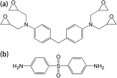
T700 carbon fiber-reinforced epoxy laminates, consisting of 4,4′-diaminodiphenylmethane (TGDDM) epoxy resin and 4,4′-diaminodiphenylsulfone (DDS) curing agent, were supplied by the Boeing Company. The chemical structures of the resin matrix and curing agent are shown in Fig. 1. The mass fraction of carbon fiber in the laminates was 70%. Di-glycidyl ether of bisphenol A (DGEBA) was supplied by Shenzhen Jiadida Chemical Co., China, and 4,4-diaminodiphenyl methane (DDM) was supplied by Beijing Chemical Industry Group Co., China. T700S-12K carbon fiber and AK-8 sizing agent were supplied by Toray Co., Japan. Zinc chloride was supplied by Aladdin Co., China.2.2. The reclaiming experiment of the composites
ZnCl2 was placed in a crucible and heated to a molten state in a muffle furnace at 360 °C. The composite samples were soaked in molten ZnCl2; then, the pyrolysis products were removed from the muffle furnace after a certain period of time (20 to 160 min). After cooling to room temperature, the products were washed repeatedly with acetone and dried for characterization.For comparative testing, the carbon fiber composites were also degraded under air conditions for the different times at 360 °C and 450 °C.
2.3. The remanufacturing of the reclaimed carbon fibers
Considering the potential applications of reclaimed carbon fibers, a commonly used epoxy resin matrix, the DGEBA/DDM system, was used for the preparation and performance evaluation of carbon fiber composites; the mass ratio of DGEBA and DDM was 100![[thin space (1/6-em)]](https://www.rsc.org/images/entities/char_2009.gif) :
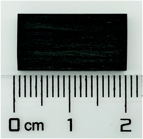
:![[thin space (1/6-em)]](https://www.rsc.org/images/entities/char_2009.gif) 20. The unidirectional carbon fiber/epoxy composites, as shown in Fig. 2, were prepared by manual layup. After the carbon fibers were impregnated, bow-shaped jigs were used to clamp both ends of the fibers to straighten them; then, the resin-impregnated fibers were placed in a unidirectional composite mold and were cured via a thermal cycle (80 °C for 2 h and 150 °C for 4 h) in an oven. The fiber volume fractions in the composite samples were 60%. To improve the interface bonding between the reclaimed carbon fibers and the epoxy matrix, the reclaimed fibers were sized with AK-8 in this study. The solid content of the AK-8 sizing agent was 3% and the sizing rate was about 1.5 wt%; the sized reclaimed carbon fibers were also used to fabricate unidirectional composite samples.
20. The unidirectional carbon fiber/epoxy composites, as shown in Fig. 2, were prepared by manual layup. After the carbon fibers were impregnated, bow-shaped jigs were used to clamp both ends of the fibers to straighten them; then, the resin-impregnated fibers were placed in a unidirectional composite mold and were cured via a thermal cycle (80 °C for 2 h and 150 °C for 4 h) in an oven. The fiber volume fractions in the composite samples were 60%. To improve the interface bonding between the reclaimed carbon fibers and the epoxy matrix, the reclaimed fibers were sized with AK-8 in this study. The solid content of the AK-8 sizing agent was 3% and the sizing rate was about 1.5 wt%; the sized reclaimed carbon fibers were also used to fabricate unidirectional composite samples.
2.4. Characterization
Because no sizing agent remained on the surface of the reclaimed carbon fibers, the virgin carbon fibers were desized before comparative characterization. The virgin carbon fibers were soaked in acetone at 80 °C for 160 hours using a Soxhlet extractor to remove the sizing agent from the carbon fiber surface.The surface morphologies of the virgin and reclaimed carbon fibers were observed using a scanning electron microscope (SEM, JEOL JSM-7800F, Japan) at 20 kV accelerating voltage and an atomic force microscope (AFM, DMFASTSCAN2-SYS, BRUKER) in tapping mode.
X-ray photoelectron spectroscopy (XPS, ESCALAB 250, Thermo) was used to examine the surface elemental composition of the carbon fibers. Surface atomic composition analysis and curve-fitting were carried out on XPSPEAK 4.1. The C 1s peak was curve-fitted using a Shirley-type background and Gaussian/Lorentzian line shapes. FWHM was optimized to obtain the curve shape.
Raman spectra of the carbon fibers were obtained using a Renishaw Micro-Raman Spectroscopy System at room temperature with an Ar+ laser light source (514 nm). The microstructures and degree of graphitization on the surface of the reclaimed carbon fibers after the different pyrolysis processes were investigated by Raman spectrometry using the Renishaw Micro-Raman Spectroscopy System connected to an optical microscope with an Ar+ laser light source (wavelength of 514 nm) at room temperature.
Single-filament tensile tests were measured according to the standard ASTM-D3379. A single filament was carefully fixed on a craft paper window with an epoxy structural adhesive, and a gauge length of 25 mm was chosen. The tensile testing was performed on a universal testing machine (Instron 3344) with a load cell of 5 N and a cross-head speed of 1 mm min−1; at least 30 specimens for each sample were successfully tested. Both sides of the specimen window were cut carefully at the mid-gauge point to leave the filament suspended between the grips of the testing machine. The carbon fiber was loaded until failure, and the force–displacement curves were recorded.
The flexure performance and interlaminar shear strength (ILSS) of the unidirectional composites were measured according to the standards ASTM-D790 and ASTM-D3846, respectively, using a universal testing machine (Instron 1121, UK). At least five specimens for each sample were successfully tested.
The chemical mechanism and degradation products of pyrolysis of the carbon fiber composites were analyzed using a pyrolysis tester (EGA/PY-3030D, Frontier Lab, Japan) and a gas chromatograph-mass spectrometer (QP2010-Ultra, Shimadzu Co., Japan).
The resin degradation ratio in a certain period of time is a reflection of the speed of the reaction and can be used to compare the efficiencies of different reclamation methods. The resin degradation ratio was calculated as:
| wd = (W0 − Wt)/(W0 × (1 − mf)) × 100% | (1) |
3. Results and discussion
3.1. Catalysis effects of ZnCl2 in the degradation process of carbon fiber/epoxy composites
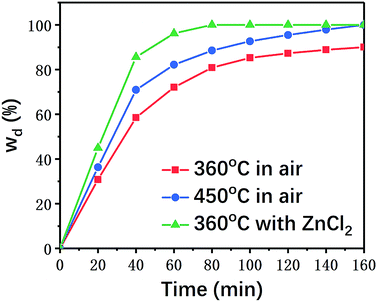
Composite material samples with the same sizes were individually placed in air and ZnCl2 at the predetermined temperature for different reaction times to calculate their resin degradation ratios. The results are summarized in Fig. 3.As shown in Fig. 3, the degradation rate of the carbon fiber/epoxy composite samples was generally enhanced with the increasing pyrolysis temperature in air. In the presence of ZnCl2 catalyst, the resin degradation ratios of the samples were significantly higher than those of the samples reacted in air at the same temperature (360 °C). ZnCl2 showed a significant accelerating effect on the degradation of the resin matrix. Even when the reaction temperature for degradation in air was increased to 450 °C, the time for complete degradation of the epoxy resin was as long as 160 min, while only 80 min were required at 360 °C under ZnCl2 catalysis.
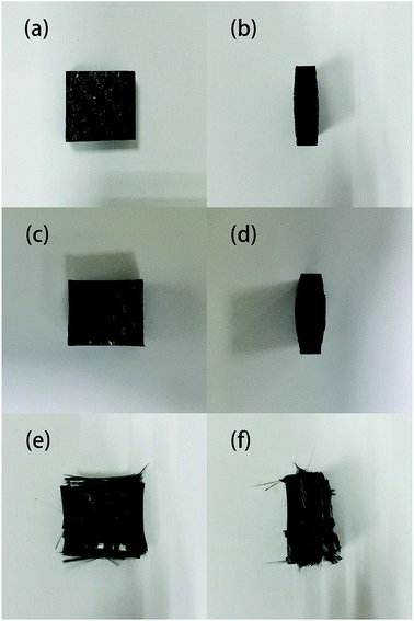
The samples after degradation for 40 minutes in different conditions are shown in Fig. 4. It can be seen that none of the samples were completely degraded; the samples that reacted with ZnCl2 appeared to swell and delaminate, while the thickness of the samples degraded in air did not substantially change even when the reaction temperature was increased to 450 °C. This is probably because the molten ZnCl2 became an ionic liquid, which has a good dissolving effect; therefore, the epoxy matrix tended to swell. After the outer layers were peeled off, the reaction area with zinc chloride further increased, accelerating the degradation reaction of the resin matrix.
3.2. Analysis of the degradation products
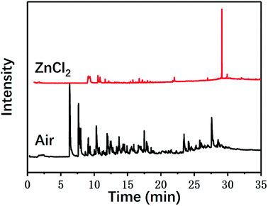
In addition to the macroscopic observation of the degradation of the composite materials and the calculation of the degradation rates, the chemical mechanism of the degradation of the carbon fiber/epoxy composites was also investigated in this study. The chemical processes and degradation products of the pyrolysis of carbon fiber composites with and without ZnCl2 were investigated using a pyrolysis tester and gas chromatograph-mass spectrometer, respectively. Fig. 5 shows the gas chromatograms. The presence of ZnCl2 had a certain impact on the pyrolysis process and the products of the composites.The main pyrolysis products generated under the two reaction conditions are shown in Table 1.
As can be seen from Table 1, some molecules containing nitrogen element were generated in the pyrolysis products under the two reaction conditions. These were mostly formed by a variety of reactions after the carbon-nitrogen bonds in the cross-linked networks of the epoxy matrix were broken. This is because the bond energies of the C–N bonds are lower throughout the cross-linked network of the epoxy matrix; thus, these bonds are more likely to break first during the pyrolysis process.27 Moreover, the Zn2+ ions in molten ZnCl2 can form organometallic complexes with C–N bonds after the resin matrix is swollen;28–32 this chemical action can promote the fracture of carbon-nitrogen bonds and thus plays a catalytic role in accelerating the degradation of the epoxy matrix. As a result, the chain scission positions of the resin with ZnCl2 were more concentrated at the C–N bonds. According to the experimental results, the proposed chain scission positions of the resin and their subsequent reactions in air and with ZnCl2, respectively, are shown in Fig. 6.
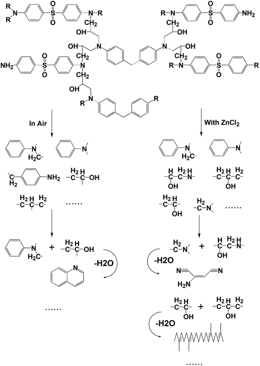 | ||
| Fig. 6 Presumed chain scission positions of the resin as along with the main small molecules produced and their subsequent reactions, both in air and with ZnCl2. | ||
3.3. Surface characteristics of the reclaimed carbon fibers
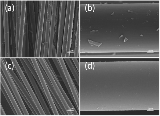
The surface morphologies of two fiber samples which were completely degraded either in ZnCl2 (360 °C/80 min) or in air (450 °C/160 min) were further observed using SEM and AFM.Fig. 7 shows SEM images of the different fiber samples. It can be observed that many resin matrix residues were left on the surfaces of the fibers reclaimed in air, whereas the fibers reclaimed with ZnCl2 exhibited very clean surfaces. This can be attributed to the catalytic effects of ZnCl2 for the degradation of the resin; also, the good compatibility of ZnCl2 with the epoxy resin facilitated detachment of the resin matrix from the fiber surface.
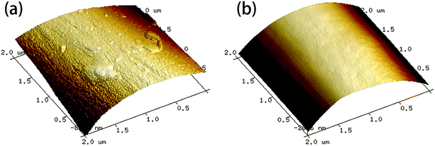
AFM images of the fiber samples are shown in Fig. 8. The surfaces of the carbon fibers reclaimed with ZnCl2 maintained a smooth morphology (Rq = 41.9 nm), indicating that ZnCl2 not only performs a catalytic function in the degradation of the epoxy matrix, but also has no corrosive effects on the carbon fibers. Meanwhile, some residues of the resin matrix and etch marks caused by the reclaiming process were observed on the surfaces of carbon the fibers reclaimed in air, which resulted in a rougher surface of the fibers (Rq = 78.6 nm).
Generally, the surface chemical groups and the microstructures of the carbon atoms of carbon fibers can affect the mechanical properties of the carbon fibers and their compatibility with the resin matrix.
In this study, XPS was used to detect changes in the surface functional groups of the carbon fibers. The surface elemental concentrations of the virgin fibers and carbon fibers reclaimed with the different processes were determined by XPS and are listed in Table 2. Fig. 9 shows the XPS survey spectra and the superimposed C 1s high-resolution spectra of several types of carbon fibers. The XPS survey spectra showed three peaks assigned to C 1s (285 eV), O 1s (531 eV) and N 1s (402 eV). To clarify the functional groups on the surface of the reclaimed carbon fibers, the C 1s spectra were curve-fitted into four individual peaks: graphitic carbon (284.6 eV), C–OH (286.1 eV), C![[double bond, length as m-dash]](https://www.rsc.org/images/entities/char_e001.gif) O (287.6 eV), and COOH (289.1 eV).31 The content of C–C in the carbon fibers reclaimed with ZnCl2 catalyst was increased compared to that of the virgin carbon fibers after desizing. The concentration of oxygenated groups, such as C–OH and COOH, decreased compared to that of the virgin carbon fibers after sizing removal. The main reason is that the carbon fiber surfaces were protected by molten ZnCl2, which prevented surface oxidation. The concentrations of C–OH and COOH groups decreased slightly and the C
O (287.6 eV), and COOH (289.1 eV).31 The content of C–C in the carbon fibers reclaimed with ZnCl2 catalyst was increased compared to that of the virgin carbon fibers after desizing. The concentration of oxygenated groups, such as C–OH and COOH, decreased compared to that of the virgin carbon fibers after sizing removal. The main reason is that the carbon fiber surfaces were protected by molten ZnCl2, which prevented surface oxidation. The concentrations of C–OH and COOH groups decreased slightly and the C![[double bond, length as m-dash]](https://www.rsc.org/images/entities/char_e001.gif) O concentration increased slightly after catalytic pyrolysis. Because the surfaces of the carbon fibers suffered from mild oxidation, the concentration of oxygenated groups of C
O concentration increased slightly after catalytic pyrolysis. Because the surfaces of the carbon fibers suffered from mild oxidation, the concentration of oxygenated groups of C![[double bond, length as m-dash]](https://www.rsc.org/images/entities/char_e001.gif) O and C–OH of the carbon fibers reclaimed in air exhibited an increase.
O and C–OH of the carbon fibers reclaimed in air exhibited an increase.
| Sample | Surface elemental composition [%] | |||
|---|---|---|---|---|
| C | N | O | O/C | |
| Virgin | 77.45 | 1.19 | 19.35 | 24.98 |
| Air | 76.47 | 2.02 | 21.51 | 28.13 |
| ZnCl2 | 78.28 | 1.68 | 18.41 | 23.51 |
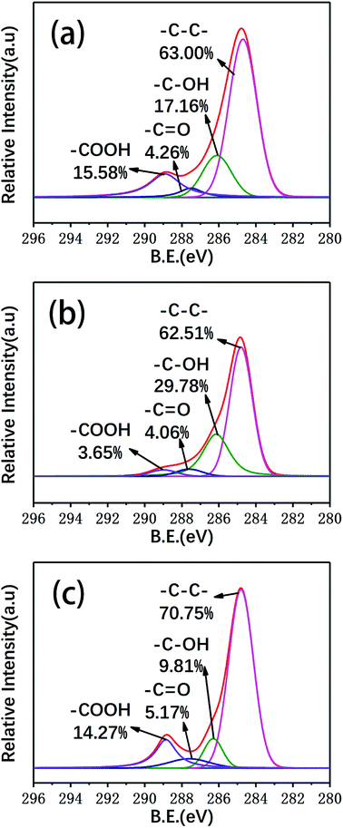 | ||
| Fig. 9 The general XPS spectra and deconvolution of the C 1s XPS spectra of (a) the virgin fibers and the fibers reclaimed (b) in air and (c) with ZnCl2. | ||
Raman spectroscopy was used to characterize the changes in the graphitization structure of the carbon fibers after the degradation process, which provided further insight into the carbon structures of the different fibers. Fig. 10 shows the Raman spectra of several types of carbon fibers. All the spectra exhibit two broad Raman bands at about 1350 and 1580 cm−1, corresponding to the D and G bands, respectively. The D band indicates the degree of disorder of the carbon atom structure, while the G band reflects the graphite crystallographic structure.32 The spectrum of single crystal graphite contains only the G band at 1580 cm−1.33,34 Therefore, the presence of the D band indicates that the degree of order of the carbon atom structure in the fibers was poor and the microcrystalline graphite was deficient, which resulted in broadening of the Raman scattering peak.
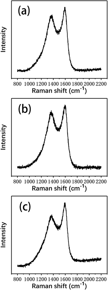 | ||
| Fig. 10 The Raman spectra of (a) the virgin fibers and the fibers reclaimed (b) in air and (c) with ZnCl2. | ||
The degree of graphitization and the integrity of a graphite structure can be judged by the relative intensity ratio of the D band, which is caused by disordered structures, and the G band, which is caused by graphite crystal (R = ID/IG).35 The smaller the R value, the higher the graphitization degree of the carbon fibers; the larger the R value, the smaller the degree of graphitization and the higher the degree of disorder. In addition, the peak width is indicative of the degree of order/disorder of the carbon fiber structure. The full widths at half maximum (FWHM) of the D band and the G band widen as the degree of structural disorder increases.
Lorentz peak fitting was performed with Origin software to obtain the Raman spectral parameters of the carbon fibers: the wave numbers (ν), the FWHM (W), and the relative intensity ratios of the D band and the G band (R) are shown in Table 3.
| Sample | νD | WD | νG | WG | R |
|---|---|---|---|---|---|
| Virgin | 1368.85 | 223.50 | 1587.63 | 93.36 | 2.19 |
| Air | 1371.28 | 242.78 | 1588.14 | 97.28 | 2.45 |
| ZnCl2 | 1368.35 | 230.89 | 1586.32 | 93.95 | 2.23 |
As shown in Table 3, the R value of the virgin fibers was the smallest, indicating that their degree of graphitization was the highest. Compared to the virgin fibers, the R value of the fibers reclaimed with ZnCl2 only increased by 0.4, indicating that the degree of graphitization showed no obvious change. However, the R value of the fibers reclaimed in air increased obviously, reflecting that the graphitization structure was more damaged. In addition, the FWHM of the fibers reclaimed in air was also significantly higher than that of those reclaimed with ZnCl2, confirming that the graphitization of carbon fibers reclaimed with the ZnCl2 catalyst remained relatively good.
3.4. Mechanical properties of the reclaimed carbon fibers
The most important feature of carbon fibers is light weight and high strength; therefore, the mechanical properties of carbon fibers after reclamation are the most important indicators to evaluate the reclamation method. In this study, single fiber tensile tests were used to characterize the tensile strengths of carbon the fibers. Because a carbon fiber monofilament is a brittle material and may have some structural defects, the tensile strength data of the monofilament tensile test are highly dispersed. A wide range of engineering applications prove that the tensile strength data of carbon fiber monofilaments obtained from tensile tests comply with two-parameter Weibull statistical probability distribution.36,37 The single fiber tensile tests were further analyzed according to the two-parameter Weibull statistical probability distribution:| F(σ) = 1 − exp(−L(σ/σ0)β) | (2) |
ln![[thin space (1/6-em)]](https://www.rsc.org/images/entities/char_2009.gif) ln(1/(1−F(σ))) = β ln(1/(1−F(σ))) = β![[thin space (1/6-em)]](https://www.rsc.org/images/entities/char_2009.gif) ln ln![[thin space (1/6-em)]](https://www.rsc.org/images/entities/char_2009.gif) σ − β σ − β![[thin space (1/6-em)]](https://www.rsc.org/images/entities/char_2009.gif) ln ln![[thin space (1/6-em)]](https://www.rsc.org/images/entities/char_2009.gif) σ0 σ0
| (3) |
The failure probability of the fibers is estimated by:
| F(σ) = i/(n + 1) | (4) |
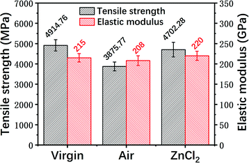
The Weibull plots of the tensile strengths of the virgin fiber and reclaimed fiber are given in Fig. 11, and the single fiber tensile strengths of the virgin fiber and reclaimed fiber after Weibull statistical processing are shown in Fig. 12.
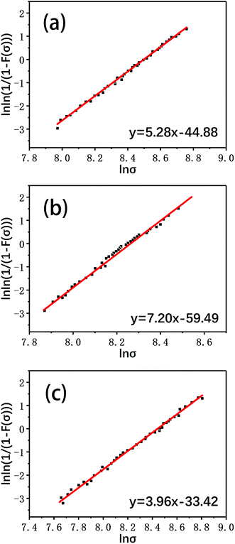 | ||
| Fig. 11 The Weibull plots of the single fiber tensile strengths of (a) a virgin fiber and fibers reclaimed (b) in air and (c) with ZnCl2. | ||
It can be seen that the mechanical strength of the carbon fiber reclaimed with ZnCl2 is much higher than that of the carbon fiber reclaimed in air. The tensile strength of the carbon fiber reclaimed with ZnCl2 exhibited a retention rate of about 95% compared to the virgin fiber. The mechanical strength of the carbon fiber reclaimed in air was only about 80% that of the virgin fiber. The elastic moduli of all the fibers remained at basically the same level. The ZnCl2 catalyst coated the carbon fiber surface during the pyrolysis process and did not react with the carbon fibers while isolating the fiber from oxygen or other substances that may corrode the fiber, thus protecting the carbon fibers from damage. However, the carbon fibers reclaimed in air were exposed to air during the degradation process of the resin matrix and were oxidized by air. This was also confirmed by the AFM, XPS and Raman data discussed previously.
3.5. Mechanical properties of reclaimed fiber-reinforced epoxy resin composites
In order to evaluate the recyclability of the reclaimed carbon fibers, virgin fibers and the reclaimed fibers were used to prepare unidirectional epoxy composites, and flexure properties and ILSS tests were carried out on the resulting composites. Considering the effects of the sizing agent, the reclaimed carbon fibers after sizing treatment were also tested in this study.Fig. 13 shows the flexure performance and the ILSS of the composite samples. With or without sizing, the composites made from fibers reclaimed with ZnCl2 were superior to the composites reinforced by fibers reclaimed in air. The differences between the mechanical properties and the surface characteristics of the fibers may lead to differences in the mechanical performance of the resulting composites. Due to the higher tensile strength and clean surface of the fibers reclaimed with ZnCl2, they showed good reinforcement. Compared to the composites made from the virgin fibers, the flexure properties and ILSS of the composites based on fibers reclaimed with ZnCl2 showed some decrease; however, after the sizing treatment, the properties of the epoxy composites containing fibers reclaimed with ZnCl2 were very similar to those of the virgin fibers-reinforced samples.
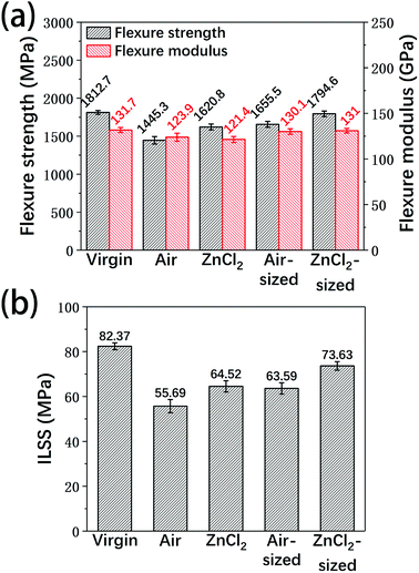 | ||
| Fig. 13 The (a) flexure properties and (b) ILSS of the unidirectional carbon fiber/epoxy composites. | ||
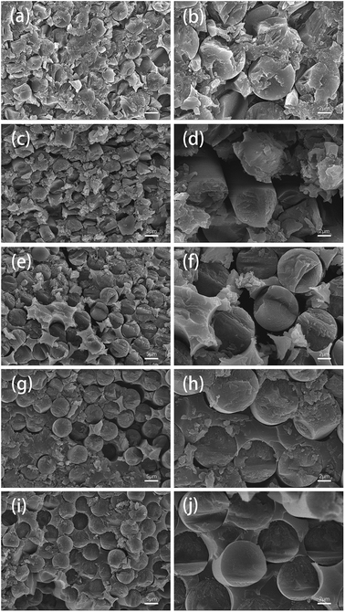
The fracture surfaces of several types of carbon fiber composites were investigated by SEM observation, as shown in Fig. 14. The interface bonding of the reclaimed fibers and the epoxy matrix obviously improved with the addition of sizing agent. The epoxy composites reinforced by carbon fibers reclaimed with ZnCl2 after sizing treatment exhibited good fracture morphology, and there was almost no gap at the cross section, similar to the samples containing virgin fibers.
4. Conclusions
The catalytic pyrolysis of T700 carbon fiber/epoxy composites using ZnCl2 molten salt was studied. The pyrolysis process utilized the efficient solubility of the molten ZnCl2 as an ionic liquid for the epoxy matrix and the catalytic fracture of the C–N bonds by the action of Zn2+ ions; thus, the epoxy composites could be completely degraded in 80 min at 360 °C, and no high pressure conditions were required. The surfaces of the reclaimed carbon fibers were clean and showed no defects. The surface characteristics and mechanical properties of the carbon fibers reclaimed with ZnCl2 were superior to those of carbon fibers reclaimed through conventional pyrolysis in air. XPS test results showed that the main oxygen-containing functional groups on the surfaces of the fibers reclaimed with ZnCl2 were similar to those of the virgin fibers, and the O/C ratio remained essentially unchanged. In the Raman spectra, the value of ID/IG indicated that the graphitization structure of the carbon fibers reclaimed with ZnCl2 was not destroyed in the pyrolysis process. The tensile strength of a monofilament of carbon fiber reclaimed with ZnCl2 exhibited a high retention rate of about 95% compared to the virgin fibers, which was obviously greater than that of the carbon fibers reclaimed in air. In the flexure performance and ILSS tests of unidirectional carbon fiber/epoxy composites, the carbon fibers reclaimed with ZnCl2 after sizing could achieve a comparable reinforcing effect to the virgin fibers. Overall, this paper presents a novel method of reclaiming carbon fibers from epoxy composite wastes with high efficiency.Conflicts of interest
The authors declared that they have no conflicts of interest to this work.Acknowledgements
This research was supported by the National Natural Science Foundation of China (No. U1664251 and No. 51873011). The authors are thankful to the Boeing Company for providing funding and materials.References
- X. Q. Zhang, H. B. Xu and X. Y. Fan, RSC Adv., 2014, 4, 12198–12205 RSC.
- B. Wielage and G. Thielemann, Adv. Eng. Mater., 2004, 6, 151–152 CrossRef.
- Y. Yang, R. Boom, B. Irion, D. J. V. Heerden, P. Kuiper and H. D. Wit, Chem. Eng. Process., 2012, 51, 53–68 CrossRef CAS.
- N. Vijay, V. Rajkumara and P. Bhattacharjee, Procedia Environ. Sci., 2016, 35, 563–570 CrossRef.
- L. Giorgini, T. Benelli, L. Mazzocchetti, C. Leonardi, G. Zattini, G. Minak, E. Dolcini, M. Cavazzoni, I. Montanari and C. Tosi, Polym. Compos., 2015, 36, 1084–1095 CrossRef CAS.
- G. Z. Jiang and S. J. Pickering, Mater. Sci. Forum, 2012, 714, 255–261 CAS.
- W. Kok, R. Chris, P. Steve and X. L. Liu, Sci. China: Technol. Sci., 2017, 60, 1–10 Search PubMed.
- S. Pimenta and S. T. Pinho, Waste Manage., 2011, 31, 378–392 CrossRef CAS PubMed.
- G. Oliveux, L. O. Dandy and G. A. Leeke, Prog. Mater. Sci., 2015, 72, 61–99 CrossRef CAS.
- S. Job, Reinf. Plast., 2013, 57, 19–23 CrossRef.
- G. Jiang, S. J. Pickering, G. S. Walker, K. H. Wong and C. D. Rudd, Appl. Surf. Sci., 2008, 254, 2588–2593 CrossRef CAS.
- S. J. Pickering, R. M. Kelly, J. R. Kennerley, C. D. Rudd and N. J. Fenwick, Compos. Sci. Technol., 2000, 60, 509–523 CrossRef CAS.
- G. Jiang, S. J. Pickering, E. H. Lester, T. A. Turner, K. H. Wong and N. A. Warrior, Compos. Sci. Technol., 2009, 69, 192–198 CrossRef CAS.
- H. Yan, C. X. Lu, D. Q. Jing, C. B. Chang, N. X. Liu and X. L. Hou, Carbon, 2016, 100, 710–711 CrossRef.
- H. Cheng, H. Huang, J. Zhang and D. Jing, Fibers Polym., 2017, 18, 795–805 CrossRef CAS.
- J. J. Jiang, G. L. Deng, X. Chen, X. Y. Gao, Q. Guo, C. M. Xu and L. C. Zhou, Compos. Sci. Technol., 2017, 151, 243–251 CrossRef CAS.
- T. Liu, M. Zhang, X. L. Guo, C. Y. Liu, T. Liu, J. N. Xin and J. W. Zhang, Polym. Degrad. Stab., 2017, 139, 20–27 CrossRef CAS.
- D. Braun, W. V. Gentzkow and A. P. Rudolf, Polym. Degrad. Stab., 2001, 74, 25–32 CrossRef CAS.
- M. H. Akonda, C. A. Lawrence and B. M. Weager, Composites, Part A, 2012, 43, 79–86 CrossRef.
- F. A. López, O. Rodríguez, F. J. Alguacil, I. García-Díaz, T. A. Centeno, J. L. García-Fierro and C. González, J. Anal. Appl. Pyrolysis, 2013, 104, 675–683 CrossRef.
- L. O. Meyer, K. Schulte and E. Grovenielsen, J. Compos. Mater., 2009, 43, 1121–1132 CrossRef CAS.
- L. Mazzocchetti, T. Benelli, E. D'Angelo, C. Leonardi, G. Zattini and L. Giorgini, Composites, Part A, 2018, 112, 504–514 CrossRef CAS.
- J. Andrzejewski, M. Misra and A. K. Mohanty, J. Appl. Polym. Sci., 2018, 135, 46449 CrossRef.
- S. Pimenta and S. Pinho, Compos. Struct., 2012, 94, 3669–3684 CrossRef.
- S. J. Pickering, Z. Liu, T. A. Turner and K. H. Wong, IOP Conf. Ser.: Mater. Sci. Eng., 2016, 139, 012005 Search PubMed.
- M. L. Longana, H. Yu, I. Hamerton and K. D. Potter, Adv. Manuf.: Polym. Compos. Sci., 2018, 4, 48–55 Search PubMed.
- J. X. Shao, X. L. Cheng, X. D. Yang, F. P. Zhang and S. H. Ge, J. At. Mol. Phys., 2006, 23, 80–84 CAS.
- S. D. Gray, K. J. Weller, M. A. Bruck, P. M. Briggs and D. E. Wigley, J. Am. Chem. Soc., 1995, 117, 10678–10693 CrossRef CAS.
- L. Yao, A. D. Wrobleski, J. E. Golden, D. R. P. And and J. Aubé, J. Am. Chem. Soc., 2005, 127, 4552–4553 CrossRef PubMed.
- T. Koreeda, T. Kochi and F. Kakiuchi, J. Am. Chem. Soc., 2009, 131, 7238–7239 CrossRef CAS PubMed.
- K. J. Weller, S. D. Gray, P. M. Briggs and D. E. Wigley, Organometallics, 2002, 14, 5588–5597 CrossRef.
- T. S. Deng, Y. Liu, X. J. Cui, Y. X. Yang, S. Y. Jia, Y. X. Wang, C. X. Lu, D. B. Li, R. Cai and X. L. Hou, Green Chem., 2015, 17, 2141–2145 RSC.
- H. Rahmani, A. Ashori and N. Varnaseri, Polym. Adv. Technol., 2016, 27, 805–811 CrossRef CAS.
- M. G. Huson, J. S. Church, A. A. Kafi, A. L. Woodhead, J. Khoo, M. S. R. N. Kiran, J. E. Bradby and B. L. Fox, Carbon, 2014, 68, 240–249 CrossRef CAS.
- D. H. Li, C. X. Lu, G. P. Wu, Y. Yang, F. An, Z. H. Feng and X. T. Li, RSC Adv., 2014, 4, 60648–60651 RSC.
- Y. Zhang, X. Wang, P. Ning and R. Postle, J. Mater. Sci., 2002, 37, 1401–1406 CrossRef CAS.
- K. Naito, J. M. Yang, Y. Tanaka and Y. Kagawa, J. Mater. Sci., 2012, 47, 632–642 CrossRef CAS.
| This journal is © The Royal Society of Chemistry 2019 |

