 Open Access Article
Influence of morphology of monolithic sulfur–poly(acrylonitrile) composites used as cathode materials in lithium–sulfur batteries on electrochemical performance†
Tim Lebherzab,
Martin Freyc,
Andreas Hintennachb and
Michael R. Buchmeiser *ad
*ad
aInstitute of Polymer Chemistry, University of Stuttgart, 70569 Stuttgart, Germany. E-mail: michael.buchmeiser@ipoc.uni-stuttgart.de
bDaimler AG, RD/EBT, HPC G012-BB, 71034 Böblingen, Germany
cDaimler AG, RD/EBB, HPC X461, 71059 Sindelfingen, Germany
dGerman Institutes of Textile and Fiber Research (DITF) Denkendorf, 73770 Denkendorf, Germany
First published on 4th March 2019
Abstract
Solvent-induced phase separation (SIPS) and thermally-induced phase separation (TIPS) derived poly(acrylonitrile) (PAN) based monoliths with different morphology and specific surface area were prepared and thermally converted into monolithic sulfur–poly(acrylonitrile) (SPAN) materials for use as active cathode materials in lithium–sulfur batteries. During thermal processing, the macroscopic monolithic structure fully prevailed while significant changes in porosity were observed. Both the monomer content in the precursor PAN-based monoliths and the tortuosity of the final monolithic SPAN materials correlate with the electrochemical performance of the SPAN-based cathodes. Overall, percolation issues predominate. In percolating SPAN-based cathode materials, the specific capacity of the SPAN-based cells increases with decreasing tortuosity. All monolithic SPAN materials provided highly reversible and cycle stable cathodes reaching reversible discharge capacities up to 1330 mA h gsulfur−1 @ 0.25C, 900 mA h gsulfur−1 @ 2C and 420 mA h gsulfur−1 @ 8C.
Introduction
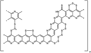
Lithium–sulfur batteries represent a promising post-Li-ion technology due to their high theoretical specific capacity of 1672 mA h gsulfur−1 and high specific energy density of 2600 W h g−1.1,2 Sulfur itself is a non-toxic, readily available and cheap cathode material. The chemistry of a Li–S-cell is based on the reversible reaction of lithium with sulfur forming Li2S according to 1/8S8 + 2Li → Li2S.3However, there are still several issues that limit the practical use of lithium–sulfur batteries.4 One is related to the mostly irreversible shuttling of polysulfides from the cathode to the anode. Thus, the reduction of elemental sulfur by elemental lithium occurs stepwise forming oligo-/polysulfides of the general formula Li2Sx (3 ≤ x ≤ 8).5 These intermediates are soluble in common ether-based electrolytes. As a result, the polysulfides are shuttling to the anode, where they are irreversibly reduced. In addition to the loss of active material, this results in a poor electrochemical efficiency of the cell and the formation of a passivating layer of Li2S on the lithium anode. Another challenge is the insulating nature of elemental sulfur, which renders its usage without any modifications and/or conversion challenging. There exist numerous approaches to overcome this issue. These entail the impregnation of carbonaceous structures such as meso- and microporous carbon black,6,7 carbon nanofibers8 or multi-walled carbon nanotubes9 with elemental sulfur. This method leads to active materials, which are resisive and render the sulfur electrochemically addressable. However, the sulfur is only physisorbed on the carbon materials, which becomes an issue in combination with electrolytes that are able to dissolve sulfur. Alternatively, a sulfur–poly(acrylonitrile) composite (SPAN), in which the sulfur is bound covalently to a condensed, polyaromatic backbone, has been developed.10,11 Briefly, for SPAN synthesis, poly(acrylonitrile) (PAN) is reacted with elemental sulfur at elevated temperature, usually between 350 and 550 °C. The resulting composite contains up to 55 wt% of sulfur and possesses substantial electric conductivity.10,12,13 We already presented a comprehensive structure of the composite that contains both thioamides and oligosulfide bridges (Fig. 1).14–16
Notably, the (vinylogous and phenylogous) thioamide groups within the structure are crucial since they function as anchoring groups for the formation of SPAN-Sx species (2 ≤ x ≤ 8) during reduction/oxidation, i.e. discharge/charge of the SPAN-matrix.17 This reversible formation of polymer-bound oligomeric sulfur species is responsible for one of the major advantages of the SPAN-composites, which is the attenuation of the polysulfide shuttle18 due to the insolubility of SPAN and all intermediates.17 Because of the absence of almost any soluble polysulfide intermediates the system also turned out to be compatible with LiPF6/carbonate-based electrolytes,19 which are commonly used for Li-ion batteries.
Finally, SPAN-based cathodes show substantially higher cycle stabilities and higher sulfur utilization (up to 90%)20 than cathodes based on elemental sulfur.1,17,21,22 One disadvantage of the SPAN-system, however, is related to its low sulfur loading of 40–55 wt% compared to cathodes based on elemental sulfur, which reach sulfur loadings up to 80 wt%.1,12,17,21,23 Nonetheless, in combination with a dimethyl trisulfide (DMTS) based electrolyte, SPAN-based cathodes are still able to reach discharge capacities up to 4 mA h cm−2.24 Similar to the working mode of SPAN cathodes outlined above, the mechanism of such a Li/SPAN/DMTS hybrid cell involves a reversible interaction of the thioamides in the SPAN-structure with CH3Sx-fragments of DMTS. The common method for the preparation of SPAN is the use of particulate PAN10,14–16,25 but it is also possible to use PAN-based fibers, which offer the advantages of better processability, defined morphology and improved percolation, which in turn results in a better electrochemical performance compared to particulate SPAN.26 In view of that, we considered monolithic SPAN a viable alternative material since it should be accessible with defined pore structure and offer sufficient percolation between the individual structure-forming microglobules. Generally, the synthesis of monolithic materials typically entails the copolymerization of a monomer and a crosslinker under solvent-induced phase separation (SIPS) conditions and results in the formation of a porous, three-dimensional polymeric network based on structure-forming microglobules in the micrometer range.27–30 The specific surface areas and pore size distribution can be influenced by the synthetic parameters such as the amount and Hildebrand solubility parameters of the solvents, the temperature and the amount of initiator.28 In addition to the synthesis via solvent-induced phase separation it is also possible to synthesize monoliths via thermally-induced phase separation (TIPS).31,32 In contrast to a SIPS based approach, in TIPS there is no polymerization involved during monolith formation. The precursor itself is a polymer, which is dissolved in a solvent mixture at higher temperatures. TIPS occurs during the cooling of the solution, thereby delivering a non-crosslinked polymeric monolith. The structure of the resulting monolith can be influenced by the solvent system and the concentration of the dissolved polymer. Here, we present the first SPAN-based monoliths as active materials with defined morphology for use in lithium–sulfur batteries and present correlations between polymer content in the PAN monoliths, microglobule packing density, tortuosity as well as percolation and electrochemical performance.
Results and discussion
Synthesis and characterization of PAN-based monoliths
Four PAN-based monoliths (PAN-1 to PAN-4) were synthesized via SIPS applying reversible addition-fragmentation-chain transfer (RAFT) polymerization.33 Acrylonitrile was used as monomer and ethyleneglycol dimethacrylate (EGDMA) as crosslinker. 2,2′-Azobis(2-methylpropionitrile) (AIBN) served as initiator, cyano-2-propyl dodecyl trithiocarbonate (CPDT) as RAFT-agent. Their concentration as well as the molar ratio of acrylonitrile![[thin space (1/6-em)]](https://www.rsc.org/images/entities/char_2009.gif) :
:![[thin space (1/6-em)]](https://www.rsc.org/images/entities/char_2009.gif) EGDMA (16
EGDMA (16![[thin space (1/6-em)]](https://www.rsc.org/images/entities/char_2009.gif) :
:![[thin space (1/6-em)]](https://www.rsc.org/images/entities/char_2009.gif) 1) was kept constant. In order to achieve different porosities and morphologies, the amounts of the solvents used for the synthesis, i.e. ethanol (EtOH), and ethylene carbonate (EC) were varied (Table 1). Complementary, two PAN-based monoliths (PAN-5 and PAN-6) were synthesized via TIPS. Different amounts of PAN (Mn = 35
1) was kept constant. In order to achieve different porosities and morphologies, the amounts of the solvents used for the synthesis, i.e. ethanol (EtOH), and ethylene carbonate (EC) were varied (Table 1). Complementary, two PAN-based monoliths (PAN-5 and PAN-6) were synthesized via TIPS. Different amounts of PAN (Mn = 35![[thin space (1/6-em)]](https://www.rsc.org/images/entities/char_2009.gif) 600 g mol−1, PDI = 3.6, c(PAN) = 60 mg mL−1 and 120 mg mL−1) were dissolved in DMSO
600 g mol−1, PDI = 3.6, c(PAN) = 60 mg mL−1 and 120 mg mL−1) were dissolved in DMSO![[thin space (1/6-em)]](https://www.rsc.org/images/entities/char_2009.gif) :
:![[thin space (1/6-em)]](https://www.rsc.org/images/entities/char_2009.gif) H2O = 88
H2O = 88![[thin space (1/6-em)]](https://www.rsc.org/images/entities/char_2009.gif) :
:![[thin space (1/6-em)]](https://www.rsc.org/images/entities/char_2009.gif) 12 (vol/vol). After cooling of the solution, PAN-based monoliths were obtained. According to N2-sorption measurements, all SIPS-derived PAN-monoliths possessed average pore diameters in the range of 30–50 nm and specific surface areas between 20 and 30 m2 g−1 in case of the SIPS-based PAN-monoliths, whereas the TIPS-derived PAN-monoliths showed higher specific surface areas of 106 m2 g−1 and 225 m2 g−1 (Table S1, ESI†).
12 (vol/vol). After cooling of the solution, PAN-based monoliths were obtained. According to N2-sorption measurements, all SIPS-derived PAN-monoliths possessed average pore diameters in the range of 30–50 nm and specific surface areas between 20 and 30 m2 g−1 in case of the SIPS-based PAN-monoliths, whereas the TIPS-derived PAN-monoliths showed higher specific surface areas of 106 m2 g−1 and 225 m2 g−1 (Table S1, ESI†).
| Monolith | m(monomers)![[thin space (1/6-em)]](https://www.rsc.org/images/entities/char_2009.gif) : :![[thin space (1/6-em)]](https://www.rsc.org/images/entities/char_2009.gif) m(solvents) m(solvents) |
Solvent system (EC/EtOH, wt%/wt%) |
|---|---|---|
| PAN-1 | 30![[thin space (1/6-em)]](https://www.rsc.org/images/entities/char_2009.gif) : :![[thin space (1/6-em)]](https://www.rsc.org/images/entities/char_2009.gif) 70 70 |
6![[thin space (1/6-em)]](https://www.rsc.org/images/entities/char_2009.gif) : :![[thin space (1/6-em)]](https://www.rsc.org/images/entities/char_2009.gif) 4 4 |
| PAN-2 | 40![[thin space (1/6-em)]](https://www.rsc.org/images/entities/char_2009.gif) : :![[thin space (1/6-em)]](https://www.rsc.org/images/entities/char_2009.gif) 60 60 |
7![[thin space (1/6-em)]](https://www.rsc.org/images/entities/char_2009.gif) : :![[thin space (1/6-em)]](https://www.rsc.org/images/entities/char_2009.gif) 3 3 |
| PAN-3 | 50![[thin space (1/6-em)]](https://www.rsc.org/images/entities/char_2009.gif) : :![[thin space (1/6-em)]](https://www.rsc.org/images/entities/char_2009.gif) 50 50 |
8![[thin space (1/6-em)]](https://www.rsc.org/images/entities/char_2009.gif) : :![[thin space (1/6-em)]](https://www.rsc.org/images/entities/char_2009.gif) 2 2 |
| PAN-4 | 60![[thin space (1/6-em)]](https://www.rsc.org/images/entities/char_2009.gif) : :![[thin space (1/6-em)]](https://www.rsc.org/images/entities/char_2009.gif) 40 40 |
1![[thin space (1/6-em)]](https://www.rsc.org/images/entities/char_2009.gif) : :![[thin space (1/6-em)]](https://www.rsc.org/images/entities/char_2009.gif) 9 9 |
The difference in specific surface areas is attributed to the two different synthetic approaches to these two monolithic systems and to the different monomer content. Clearly, the freeze-drying process of the non-crosslinked TIPS-derived PAN-monoliths influences the resulting porosity of the monolith and generates a higher BET surface area. Scanning electron microscopy images of all monoliths showed a typical monolithic structure, consisting of agglomerated structure-forming microglobules (Fig. 2).
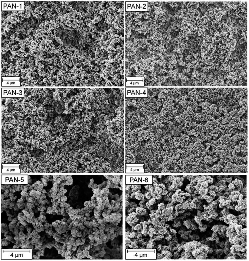 | ||
| Fig. 2 SEM-pictures of the SIPS-derived PAN-monoliths PAN-1 to PAN-4 and the TIPS-derived PAN-monoliths PAN 5 and PAN 6. | ||
Synthesis and characterization of SPAN-monoliths
SPAN-monoliths were synthesized via reaction of S8 with the polymeric monoliths PAN-1 to PAN-6 according to procedures described for pellicular SPAN.26 The elemental composition of the materials was determined via elemental analysis and is summarized in Table 2.| SPAN-1 | SPAN-2 | SPAN-3 | SPAN-4 | SPAN-5 | SPAN-6 | |
|---|---|---|---|---|---|---|
| C [%] | 44.55 | 44.85 | 44.2 | 44.05 | 40.68 | 39.57 |
| H [%] | 1.09 | 1.24 | 1.18 | 1.11 | 1.02 | 0.91 |
| N [%] | 12.24 | 11.91 | 12.36 | 12.22 | 13.65 | 13.51 |
| S [%] | 38.8 | 38.9 | 39.4 | 40.6 | 38.4 | 40.8 |
| O [%] | 3.3 | 3.1 | 2.9 | 2.0 | 6.3 | 5.2 |
C![[thin space (1/6-em)]](https://www.rsc.org/images/entities/char_2009.gif) : :![[thin space (1/6-em)]](https://www.rsc.org/images/entities/char_2009.gif) H (Atomic ratio) H (Atomic ratio) |
3.40 | 3.01 | 3.12 | 3.31 | 3.34 | 3.61 |
C![[thin space (1/6-em)]](https://www.rsc.org/images/entities/char_2009.gif) : :![[thin space (1/6-em)]](https://www.rsc.org/images/entities/char_2009.gif) N (Atomic ratio) N (Atomic ratio) |
4.25 | 4.39 | 4.17 | 4.21 | 3.48 | 3.42 |
| dp [nm] | 4.0 | 4.0 | 4.2 | 3.5 | 3.9 | 4.0 |
| σ [m2 g−1] | 14 | 24 | 23 | 18 | 116 | 97 |
| Vp [cm3 g−1] | 0.04 | 0.08 | 0.10 | 0.08 | 0.24 | 0.16 |
All synthesized SPAN-monoliths showed an S-content around 40 wt%. The atomic C![[thin space (1/6-em)]](https://www.rsc.org/images/entities/char_2009.gif) :
:![[thin space (1/6-em)]](https://www.rsc.org/images/entities/char_2009.gif) H ratio was between 3.0 and 3.6 throughout. The high C
H ratio was between 3.0 and 3.6 throughout. The high C![[thin space (1/6-em)]](https://www.rsc.org/images/entities/char_2009.gif) :
:![[thin space (1/6-em)]](https://www.rsc.org/images/entities/char_2009.gif) H ratio indicates substantial dehydrogenation during formation of the SPAN structure and, concomitant formation of the polyannelated, cyclic, nitrogen-containing backbone. Conversion of the PAN-based monolith into the SPAN-monolith was also monitored by IR-spectroscopy (Fig. S23 and S24, ESI†), which revealed the disappearance of the nitrile band and formation of the typical SPAN structure.14–16 Thus, the spectra of the PAN-monoliths PAN-1 to PAN-6 showed one characteristic band, i.e. the nitrile stretching of the acrylonitrile at 2240 cm−1 and in case of the PAN-monoliths PAN-1 to PAN-4 in addition the ester band of the crosslinker at 1725 cm−1. Both bands disappeared after reaction with elemental sulfur. The IR-spectrum of the SPAN-monolith showed only one strong broad band in the range of 1000–1600 cm−1.
H ratio indicates substantial dehydrogenation during formation of the SPAN structure and, concomitant formation of the polyannelated, cyclic, nitrogen-containing backbone. Conversion of the PAN-based monolith into the SPAN-monolith was also monitored by IR-spectroscopy (Fig. S23 and S24, ESI†), which revealed the disappearance of the nitrile band and formation of the typical SPAN structure.14–16 Thus, the spectra of the PAN-monoliths PAN-1 to PAN-6 showed one characteristic band, i.e. the nitrile stretching of the acrylonitrile at 2240 cm−1 and in case of the PAN-monoliths PAN-1 to PAN-4 in addition the ester band of the crosslinker at 1725 cm−1. Both bands disappeared after reaction with elemental sulfur. The IR-spectrum of the SPAN-monolith showed only one strong broad band in the range of 1000–1600 cm−1.
This band is characteristic for SPAN-materials and is caused by the vibrations of the condensed, aromatic, pyridine-like structure. The bands in the region of 600–900 cm−1 are most likely caused by the vibrations of the thioamide groups.34 The absence of the adsorption bands of both the nitrile and the ester group indicates that both infiltration with liquid sulfur and thermally-induced conversion of PAN to SPAN was complete and the crosslinker was thermally eliminated. Clearly, both the elimination of the crosslinker and the dehydrogenation of the PAN during the conversion into SPAN generated small mesopores, which resulted into a decrease in the average pore diameter to approximately 4 nm (Fig. S7–S12, ESI†). Notably, despite the significant changes on the molecular level, conversion of PAN to SPAN occurred under retention of the macroscopic structure of the monolith, as shown in Fig. 3. SEM images of the SPAN-monoliths (Fig. S19–S21, ESI†) also confirmed the retention of the porous monolithic structure. Notably, this is one of the comparably rare examples for the conversion of a porous polymeric network into a carbonaceous one under full retention of both the microscopic and the macroscopic structure.35,36
Electrochemistry
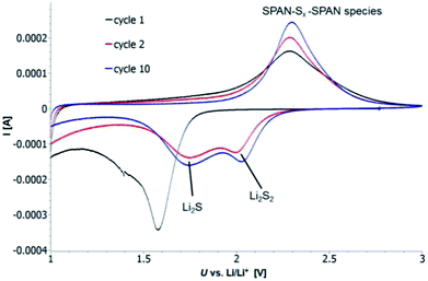
Cyclic voltammetry (CV) was carried out in the range between 1 and 3 V. Fig. 4 shows the representative cyclic voltammogram of monolithic SPAN-4. The CVs of all active materials looked very similar. The first discharge cycle shows a broad signal with a maximum at 1.6 V and differs from all following cycles due to the irreversible reduction of the backbone of the SPAN-matrix.17,37 This phenomenon is well known for SPAN-based cathode materials.17,37 All following discharge cycles show the same curvature with a broad bimodal signal with maxima at 1.75 and 2.05 V, respectively.38–40 These indicate the formation of Li2S and Li2S2 according to SPAN-Sx + 2Li → Li2Sy + SPAN-Sx−y with 2 ≤ x ≤ 7 and 1 < y < 2. All oxidation cycles in CV, including the first cycle, show a broad signal at 2.3 V which indicates the formation of SPAN-Sx-SPAN species according to SPAN-Sx−1-SPAN + Li2S → SPAN-Sx-SPAN + 2 Li with 2 ≤ x ≤ 8.37,41 The performance of the Li/SPAN-system was tested in a symmetrical stress test. The Li–S-cells were charged and discharged at different C-rates, starting and ending with 0.25C and applying a maximum C-rate of 2C. The results of the symmetrical stress tests are shown in Fig. 5 and 6; the initial discharge capacities of the cells are summarized in Table 3. The best monolithic SPAN-material (SPAN-4) showed a high specific discharge capacity of 900 mA h gsulfur−1 at 2C. In addition to these experiments we performed cycle tests with each active material with a charge/discharge rate of 1C (Fig. 7 and 8).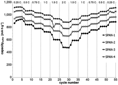 | ||
| Fig. 5 Symmetrical stress test 0.25C–2C–0.25C of cells prepared from the SIPS-derived SPAN-based monoliths SPAN-1 to SPAN-4. | ||
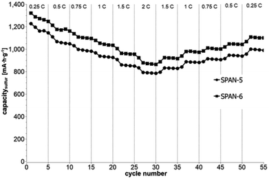 | ||
| Fig. 6 Symmetrical stress test 0.25C–2C–0.25C of cells prepared from the TIPS-derived SPAN-based monoliths SPAN-5 and SPAN-6. | ||
| Initial discharge capacity [mA h g−1] | |
|---|---|
| SPAN-1 | 1416 |
| SPAN-2 | 1478 |
| SPAN-3 | 1560 |
| SPAN-4 | 1601 |
| SPAN-5 | 1671 |
| SPAN-6 | 1721 |
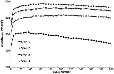 | ||
| Fig. 7 Cycle test with 1C of cells prepared from the SIPS-derived SPAN-based monoliths SPAN-1 to SPAN-4. | ||
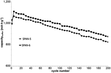 | ||
| Fig. 8 Cycle test with 1C of cells based on the TIPS-derived SPAN-based monoliths SPAN-5 and SPAN-6. | ||
Even after 200 cycles, cells based on SPAN-2 to SPAN-4 showed only a minor loss in capacity (5%) and the coulombic efficiency of the cells was >99% throughout. This strongly suggests that in these cathode materials both the reduction and oxidation of the monolithic SPAN-matrices proceeds in a highly reversible manner, at least up to 200 cycles. By contrast, the TIPS-derived SPAN monoliths SPAN-5 and SPAN-6 showed high initial discharge capacities (Fig. 6, Table 3) but a more pronounced loss in discharge capacities within 200 cycles (Fig. 8). These distinct differences in electrochemical performance deserve attention, the more since the materials are virtually chemically identical and the conductivity of all our (pressed) monolithic SPAN-materials is similar and <10−8 S cm−1. Conductivity of the parent material is thus somewhat lower than the one of particulate SPAN (10−6 S cm−1),42 which can be explained by the higher porosity of monolithic SPAN compared to particulate SPAN. Consequently, the differences in electrochemical performance must be a result of the materials' different microstructure. We attribute the high initial capacity of all SPAN monoliths is attributed to the small mesopores in the range of 3.5–4.2 nm that are present in SPAN as evidenced by N2-sorption experiments (Fig. S7–S12, ESI†). These guarantee for a good wetting of the active material with the electrolyte. They also provide sufficient specific surface area (14 < σ < 116 m2 g−1) allowing substantial diffusion of lithium ions during reduction/oxidation to and from the SPAN-matrix. Such fast diffusion and mass transfer, respectively, is particularly important at higher C-rates. In addition to these small mesopores, there are also interparticle voids in the range of 100–1000 nm present, as confirmed by mercury porosimetry (Fig. S13–S18, Table S2†). These macropores guarantee for a sufficient amount of electrolyte. In addition, there is an irreversible reduction of the backbone of the SPAN-matrix in the first discharge cycle, which delivers higher discharge capacities. For SPAN-6 this results in a discharge capacity, which is even higher than the theoretical capacity of sulfur. This phenomenon is well-known for SPAN-based active materials.17,38 The substantial differences in electrochemical performance between the individual active SPAN-based materials SPAN-1 to SPAN-4 are attributed to the different monomer content in the monolithic PAN-precursor and, accordingly, in the corresponding monolithic SPAN. Obviously, percolation between the individual micrometer-sized structure-forming microglobules plays a major role, rendering SPAN-2 to SPAN-4, which have the highest monomer content, superior to all other materials, including the TIPS-derived ones, which are prepared from PAN/solvent mixtures with a comparably low polymer loading (PAN![[thin space (1/6-em)]](https://www.rsc.org/images/entities/char_2009.gif) :
:![[thin space (1/6-em)]](https://www.rsc.org/images/entities/char_2009.gif) solvent = 6
solvent = 6![[thin space (1/6-em)]](https://www.rsc.org/images/entities/char_2009.gif) :
:![[thin space (1/6-em)]](https://www.rsc.org/images/entities/char_2009.gif) 100 and 12
100 and 12![[thin space (1/6-em)]](https://www.rsc.org/images/entities/char_2009.gif) :
:![[thin space (1/6-em)]](https://www.rsc.org/images/entities/char_2009.gif) 100, respectively, see Experimental section). In addition to the characterization of the monolithic SPAN-materials via mercury intrusion, nitrogen adsorption and SEM imaging, the tortuosity of the individual cathodes were measured via a Polarization-Interrupt-Experiment.43,44 Tortuosity is not universally defined in literature, but a common definition is the ratio of the average pore length Leff to the length of the porous medium L along the diffusion axis.45 According to this the tortuosity τ is given by:
100, respectively, see Experimental section). In addition to the characterization of the monolithic SPAN-materials via mercury intrusion, nitrogen adsorption and SEM imaging, the tortuosity of the individual cathodes were measured via a Polarization-Interrupt-Experiment.43,44 Tortuosity is not universally defined in literature, but a common definition is the ratio of the average pore length Leff to the length of the porous medium L along the diffusion axis.45 According to this the tortuosity τ is given by:
 | (1) |
During polarization of the cell, Li+ ions are diffusing from the anode to the cathode. Once polarization is stopped, the cell relaxes and the Li+-ions have to pass through the porous layer between the separators. The relaxation time tr depends on the morphology and the average pore length Leff of the active material. This way, tortuosity can be determined by measuring the relaxation time. Substitution of Leff by tr in eqn (1) gives the tortuosities listed in Table 4, which are calculated based on the relaxation time of the cells and the thickness of the coating.
| Tortuosity τ | |
|---|---|
| SPAN-1 | 2.14 |
| SPAN-2 | 1.21 |
| SPAN-3 | 0.98 |
| SPAN-4 | 0.75 |
| SPAN-5 | 1.34 |
| SPAN-6 | 1.72 |
The electrochemical behavior of the cells based on SIPS-derived SPAN-monoliths as active materials (SPAN-1 to SPAN-4) correlates with the determined tortuosities. The higher the tortuosity of the materials is, the lower the discharge capacities of the cells are (Fig. S22†). Furthermore, tortuosity of the active material correlates with the monomer content in the precursor PAN-monoliths. The less compact SPAN-monolith SPAN-1 shows the highest tortuosity (2.14) while the most compact monolith SPAN-4 possesses the lowest tortuosity (0.75). Compared to SIPS-derived SPAN-monoliths, TIPS-derived SPAN-monoliths generally showed high tortuosities, which is in view of the comparably low amounts of PAN used for their synthesis not surprising. Clearly, the low PAN![[thin space (1/6-em)]](https://www.rsc.org/images/entities/char_2009.gif) :
:![[thin space (1/6-em)]](https://www.rsc.org/images/entities/char_2009.gif) solvent ratios used TIPS-derived PAN-monoliths, lead to higher porosity and higher tortuosity. In addition, no crosslinking occurs in TIPS-derived SPAN-monoliths, which results in poor mechanical stability. Consequently, no clear correlation between electrochemistry and tortuosity can be achieved.
solvent ratios used TIPS-derived PAN-monoliths, lead to higher porosity and higher tortuosity. In addition, no crosslinking occurs in TIPS-derived SPAN-monoliths, which results in poor mechanical stability. Consequently, no clear correlation between electrochemistry and tortuosity can be achieved.
In view of its superior performance, the SPAN-4 monolith was additionally compared to a state-of-the-art fibrous SPAN cathode material reported earlier.26,37 The comparison was done in form of a symmetrical stress test, starting at 0.5C with a maximum charge/discharge rate of 8C. It is remarkable that at a charge/discharge rate of 8C the SPAN-based monolith still outperformed the fibrous SPAN in terms of specific capacity (420 vs. 300 mA h gsulfur−1,26 Fig. S25, ESI†). Compared to fibrous SPAN, the monolithic SPAN showed a similar cycle behavior but reached higher discharge capacities at all C-rates (Table 5). Even at high C-rates up to 8C the coulombic efficiency of the cell was >99%.
| C-rate | Capacitysulfur22 (fibrous SPAN, mA h g−1) | Capacitysulfur (monolithic SPAN-4, mA h g−1) |
|---|---|---|
| 0.5C | 1040 | 1050 |
| 1C | 950 | 990 |
| 2C | 800 | 890 |
| 3C | 650 | 790 |
| 4C | 550 | 680 |
| 6C | 350 | 500 |
| 8C | 300 | 420 |
Experimental section
Ethylene carbonate (EC, for electrochemistry, 99.9%, anhydrous), EC (for monolith synthesis, >98%), dimethyl carbonate (DMC, >99%, anhydrous), sulfur (99.5%, sublimed), cyano-2-propyl dodecyl trithiocarbonate (CPDT, >98%), 2,2′-azobis(2-methyl-propionitrile) (AIBN, >98%), poly(acrylonitrile) (PAN, Mn = 36![[thin space (1/6-em)]](https://www.rsc.org/images/entities/char_2009.gif) 500 g mol−1, PDI = 3.6), dimethyl sulfoxide (DMSO, 99%) and lithium bis(trifluoromethanesulfonyl)imide (LiTFSI, 99.95%) were purchased from Sigma-Aldrich (Munich, Germany). LiTFSI was dried in vacuo at 150 °C overnight prior to use. AIBN was recrystallized twice from methanol prior to use. Ethylene gycol dimethacrylate (EGDMA, >97%, TCI, Zwijndrecht, Belgium), acrylonitrile (AN, >99%, Merck, Darmstadt, Germany), Super C65 (Timcal, Bodio, Switzerland), poly(vinyl difluoride) (PVDF, Solvay, Brussels, Belgium), elemental lithium (>99.9%, Alfa Aesar, Karlsruhe, Germany) and N-methyl-2-pyrrolidone (NMP, >99.5%, TCI, Zwijndrecht, Belgium) were used as received.
500 g mol−1, PDI = 3.6), dimethyl sulfoxide (DMSO, 99%) and lithium bis(trifluoromethanesulfonyl)imide (LiTFSI, 99.95%) were purchased from Sigma-Aldrich (Munich, Germany). LiTFSI was dried in vacuo at 150 °C overnight prior to use. AIBN was recrystallized twice from methanol prior to use. Ethylene gycol dimethacrylate (EGDMA, >97%, TCI, Zwijndrecht, Belgium), acrylonitrile (AN, >99%, Merck, Darmstadt, Germany), Super C65 (Timcal, Bodio, Switzerland), poly(vinyl difluoride) (PVDF, Solvay, Brussels, Belgium), elemental lithium (>99.9%, Alfa Aesar, Karlsruhe, Germany) and N-methyl-2-pyrrolidone (NMP, >99.5%, TCI, Zwijndrecht, Belgium) were used as received.
The IR spectra were recorded on an IFS 128 ATR/FT-IR-spectrometer of Bruker in the range of 400 cm−1 to 4000 cm−1. Scanning electron micrograph (SEM) images were recorded at the German Institutes of Textile and Fiber Research, DITF Denkendorf, using an Auriga type field emission scanning electron microscope from Zeiss. The samples were sputtered with Pt/Pd before measuring.
Synthesis of PAN-based monoliths via SIPS
Acrylonitrile (AN, 16 eq.), EGDMA (1 eq.), EC, ethanol (EtOH), CPDT, and AIBN were mixed in a vial and heated to 75 °C for 18 h. The concentration of the initiator and the RAFT-agent was the same in the synthesis of all monoliths (c(AIBN) = 0.78 mg mL−1 and c(CPDT) = 4 mg mL−1). The solvent system and the ratio of solvents![[thin space (1/6-em)]](https://www.rsc.org/images/entities/char_2009.gif) :
:![[thin space (1/6-em)]](https://www.rsc.org/images/entities/char_2009.gif) monomers were varied in order to obtain four monoliths with different morphology. The composition of the solutions is shown in Table 1. After cooling to room temperature, all monoliths were washed with EtOH and dried in vacuo. Monoliths were characterized via nitrogen adsorption and desorption measurements and scanning electron microscopy (SEM).
monomers were varied in order to obtain four monoliths with different morphology. The composition of the solutions is shown in Table 1. After cooling to room temperature, all monoliths were washed with EtOH and dried in vacuo. Monoliths were characterized via nitrogen adsorption and desorption measurements and scanning electron microscopy (SEM).
Synthesis of PAN-based monoliths via TIPS
PAN (c(PAN) = 60 mg mL−1 for PAN-5 and 120 mg mL−1 for PAN-6) was dissolved within four hours in an DMSO/water mixture (vol/vol = 88![[thin space (1/6-em)]](https://www.rsc.org/images/entities/char_2009.gif) :
:![[thin space (1/6-em)]](https://www.rsc.org/images/entities/char_2009.gif) 12) at 100 °C. After the solution was allowed to cool to room temperature, the obtained monoliths were washed several times with water and were freeze-dried. Monoliths were characterized via nitrogen adsorption and desorption measurements and SEM.
12) at 100 °C. After the solution was allowed to cool to room temperature, the obtained monoliths were washed several times with water and were freeze-dried. Monoliths were characterized via nitrogen adsorption and desorption measurements and SEM.
Synthesis of SPAN-monoliths
PAN-monoliths were converted into SPAN-monoliths via treatment with excess elemental sulfur at 550 °C for 5 h under a nitrogen atmosphere. Residual sulfur was removed after synthesis with toluene (Soxhlet extraction for 48 hours).26 The resulting materials were characterized via elemental analysis and IR spectroscopy. The morphology of the SPAN-materials was characterized via SEM, nitrogen adsorption and desorption measurements and mercury porosimetry.Electrochemistry
SPAN-monoliths were ground and sieved to achieve an average particle size < 63 μm. A dispersion of SPAN/Super C65/PVDF (70/15/15, wt%) in NMP was coated on a carbon-coated aluminum foil (200 μmwet). The sulfur loading of the cathodes was 0.5 mg cm−2. After drying at 60 °C, cathodes 12 mm in diameter were punched out of the sheet and transferred into an argon filled glovebox. Swagelok T-type cells were used for electrochemical characterization. Elemental lithium was used as anode, two Freudenberg FS 2190 membranes were used as separators and a freshly prepared 3 M solution of LiTFSI in EC/DMC (1![[thin space (1/6-em)]](https://www.rsc.org/images/entities/char_2009.gif) :
:![[thin space (1/6-em)]](https://www.rsc.org/images/entities/char_2009.gif) 1) was used as electrolyte. All electrochemical measurements were performed on a BasyTec XCTS-LAB battery test station. The specific capacity and charge/discharge rates were calculated based on the mass of sulfur in the cathode (1C = 1672 mA h g−1).
1) was used as electrolyte. All electrochemical measurements were performed on a BasyTec XCTS-LAB battery test station. The specific capacity and charge/discharge rates were calculated based on the mass of sulfur in the cathode (1C = 1672 mA h g−1).
Tortuosity
Tortuosity was measured in a Polarization-Interrupt-Experiment.43,44 For these purposes, the coating was removed from the current collector with an aqueous solution of sodium hydroxide and then washed several times with demineralized water. The coating was dried and sandwiched between two separators. For the measurements a symmetrical cell setup was used (Li vs. Li) with the separator-coating-separator sandwich in between. The electrolyte was 3 M LiTFSI in EC/DMC (1![[thin space (1/6-em)]](https://www.rsc.org/images/entities/char_2009.gif) :
:![[thin space (1/6-em)]](https://www.rsc.org/images/entities/char_2009.gif) 1). The cells were polarized with 2 mA for two minutes, then the relaxation time was measured until the cell voltage reached 0 V (±0.0005 V).
1). The cells were polarized with 2 mA for two minutes, then the relaxation time was measured until the cell voltage reached 0 V (±0.0005 V).
Conclusions
We synthesized six different PAN-monoliths, both via solvent-induced and thermally-induced phase separation. All PAN-monoliths were characterized and converted into SPAN-monoliths through the reaction with elemental sulfur at 550 °C. In course of the conversion process the porous macroscopic, monolithic structure was preserved. A sulfur content around 40 wt% was reached throughout. Both the PAN- and SPAN-monoliths showed a defined structure in SEM and high specific surface areas up to 225 m2 g−1. The infrared spectra of the resulting SPAN monoliths as well as the atomic C![[thin space (1/6-em)]](https://www.rsc.org/images/entities/char_2009.gif) :
:![[thin space (1/6-em)]](https://www.rsc.org/images/entities/char_2009.gif) H and C
H and C![[thin space (1/6-em)]](https://www.rsc.org/images/entities/char_2009.gif) :
:![[thin space (1/6-em)]](https://www.rsc.org/images/entities/char_2009.gif) N ratios indicate the formation of the desired SPAN-structure. Conversion of monolithic PAN into monolithic SPAN proceeded under retention of the shape of the monolithic structure. Both the SIPS- and TIPS-derived SPAN monoliths allowed for the preparation SPAN-based Li–S cells. TIPS-derived SPAN monoliths performed poorly in terms of cycle stability. Our current explanation for this behavior relates to poor percolation and high tortuosities caused by a low monomer content. By contrast, SIPS-derived SPAN monoliths show high initial capacity and good cycle stability provided substantial percolation and lower tortuosities as is the case in SPAN-2 to SPAN-4. The electrochemical performance of monolithic SPAN materials correlates with tortuosity and even exceeds the one of fibrous SPAN reaching a specific capacity of up to 1330 mA h gsulfur−1 @ 0.25C (sulfur utilization of 80%), 900 mA h gsulfur−1 @ 2C (sulfur utilization of 54%) and 420 mA h gsulfur−1 @ 8C (sulfur utilization of 25%).
N ratios indicate the formation of the desired SPAN-structure. Conversion of monolithic PAN into monolithic SPAN proceeded under retention of the shape of the monolithic structure. Both the SIPS- and TIPS-derived SPAN monoliths allowed for the preparation SPAN-based Li–S cells. TIPS-derived SPAN monoliths performed poorly in terms of cycle stability. Our current explanation for this behavior relates to poor percolation and high tortuosities caused by a low monomer content. By contrast, SIPS-derived SPAN monoliths show high initial capacity and good cycle stability provided substantial percolation and lower tortuosities as is the case in SPAN-2 to SPAN-4. The electrochemical performance of monolithic SPAN materials correlates with tortuosity and even exceeds the one of fibrous SPAN reaching a specific capacity of up to 1330 mA h gsulfur−1 @ 0.25C (sulfur utilization of 80%), 900 mA h gsulfur−1 @ 2C (sulfur utilization of 54%) and 420 mA h gsulfur−1 @ 8C (sulfur utilization of 25%).
Conflicts of interest
There are no conflicts to declare.Acknowledgements
This work was financially supported by the German Federal Ministry for Economic Affairs and Energy (BMWi, project no. S50400). The authors wish to thank U. Hageroth and S. Henzler (DITF Denkendorf) for SEM measurements and M. Wieland (Institute of Polymer Chemistry, University of Stuttgart), J. Trueck (Daimler AG) and E. Hadjixenophontos (Institute of Materials Science, University of Stuttgart) for four-point-resistivity measurements.References
- A. Manthiram, Y. Fu, S. H. Chung, C. Zu and Y. S. Su, Chem. Rev., 2014, 114, 11751–11787 CrossRef CAS PubMed
.
- X. Chen, T. Hou, K. Persson and A. Q. Zhang, Mater. Today, 2018 DOI:10.1016/j.mattod.2018.04.007
.
- M. Wild, L. O'Neill, T. Zhang, R. Purkayastha, G. Minton, M. Marinescu and G. J. Offer, Energy Environ. Sci., 2015, 8, 3477–3494 RSC
.
- M. Arumugam, Y. Fu and A.-S. Su, Acc. Chem. Res., 2013, 46, 1125–1134 Search PubMed
.
- M. R. Busche, P. Adelhelm, H. Sommer, H. Schneider, K. Leitner and J. Janek, J. Power Sources, 2014, 259, 289–299 CrossRef CAS
.
- B. Zhang, X. Qin, G. R. Li and X. P. Gao, Energy Environ. Sci., 2010, 3, 1531 RSC
.
- X. Li, Y. Cao, W. Qi, L. V. Saraf, J. Xiao, Z. Nie, J. Mietek, J.-G. Zhang, B. Schwenzer and J. Liu, J. Mater. Chem., 2011, 21, 16603 RSC
.
- J. S. Lee, W. Kim, J. Jang and A. Manthiram, Adv. Energy Mater., 2017, 7, 1601943 CrossRef
.
- Y. S. Su, Y. Fu and A. Manthiram, Phys. Chem. Chem. Phys., 2012, 14, 14495–14499 RSC
.
- J. Wang, J. Yang, J. Xie and N. Xu, Adv. Mater., 2002, 14, 963–965 CrossRef CAS
.
- W. Wang, Z. Cao, G. A. Elia, Y. Wu, W. Wahyudi, E. Abou-Hamad, A.-H. Emwas, L. Cavallo, L.-J. Li and J. Ming, ACS Energy Lett., 2018, 3, 2899–2907 CrossRef CAS
.
- J. Wang, J. Yang, C. Wan, K. Du, J. Xie and N. Xu, Adv. Funct. Mater., 2003, 13, 487–492 CrossRef CAS
.
- X. Yu, J. Xie, J. Yang, H. Huang, K. Wang and Z. Wen, J. Electroanal. Chem., 2004, 573, 121–128 CAS
.
- J. Fanous, M. Wegner, J. Grimminger, Ä. Andresen and M. R. Buchmeiser, Chem. Mater., 2011, 23, 5024–5028 CrossRef CAS
.
- J. Fanous, M. Wegner, M. B. M. Spera and M. R. Buchmeiser, J. Electrochem. Soc., 2013, 160, A1169–A1170 CrossRef CAS
.
- J. Fanous, M. Wegner, J. Grimminger, M. Rolff, M. B. M. Spera, M. Tenzer and M. R. Buchmeiser, J. Mater. Chem., 2012, 22, 23240–23245 RSC
.
- S. Zhang, Energies, 2014, 7, 4588–4600 Search PubMed
.
- S. Wei, L. Ma, K. E. Hendrickson, Z. Tu and L. A. Archer, J. Am. Chem. Soc., 2015, 137, 12143–12152 CrossRef CAS PubMed
.
- S. Warneke, A. Hintennach and M. R. Buchmeiser, J. Electrochem. Soc., 2018, 165, A2093–A2095 CrossRef CAS
.
- Z. Chen, J. Zhou, Y. Guo, C. Liang, J. Yang, J. Wang and Y. Nuli, Electrochim. Acta, 2018, 282, 555–562 CrossRef CAS
.
- L. Wang, X. He, J. Li, J. Gao, J. Guo, C. Jiang and C. Wan, J. Mater. Chem., 2012, 22, 22077 RSC
.
- C.-F. J. Kuo, M. A. Weret, H.-Y. Hung, M.-C. Tsai, C.-J. Huang, W.-N. Su and B.-J. Hwang, J. Power Sources, 2019, 412, 670–676 CrossRef CAS
.
- Y. X. Yin, S. Xin, Y. G. Guo and L. J. Wan, Angew. Chem., Int. Ed., 2013, 125, 13426–13441 CrossRef
.
- S. Warneke, R. K. Zenn, T. Lebherz, K. Müller, A. Hintennach, U. Starke, R. E. Dinnebier and M. R. Buchmeiser, Adv. Sustainable Syst., 2018, 2, 1700144 CrossRef
.
- W. Pu, X. He, L. Wang, Z. Tian, C. Jiang and C. Wan, Ionics, 2007, 13, 273–276 CrossRef CAS
.
- M. Frey, R. K. Zenn, S. Warneke, K. Müller, A. Hintennach, R. E. Dinnebier and M. R. Buchmeiser, ACS Energy Lett., 2017, 2, 595–604 CrossRef CAS
.
- M. R. Buchmeiser, Angew. Chem., Int. Ed., 2001, 113, 3911–3913 CrossRef
.
- M. R. Buchmeiser, Polymer, 2007, 48, 2187–2198 CrossRef CAS
.
- J. M. J. Frechet and F. Svec, Anal. Chem., 1992, 64, 820–822 CrossRef
.
- F. Svec and J. M. J. Frechet, Macromolecules, 1995, 28, 7580–7582 CrossRef CAS
.
- K. Okada, M. Nandi, J. Maruyama, T. Oka, T. Tsujimoto, K. Kondoh and H. Uyama, Chem. Commun., 2011, 47, 7422–7424 RSC
.
- W. Gang, J. Wang, H. Zhang, Z. Fei, T. Wu, Q. Ren and J. Qiu, Chem. Eng. J., 2016, 313, 1607–1614 Search PubMed
.
- J. M. Spörl, A. Ota, R. Beyer, T. Lehr, A. Müller, F. Hermanutz and M. R. Buchmeiser, J. Polym. Sci., Part A: Polym. Chem., 2014, 52, 1322–1333 Search PubMed
.
- H. O. Desseyn, B. J. Van Der Veken and M. A. Herman, Appl. Spectrosc., 1978, 32, 101–105 CrossRef CAS
.
- M. Antonietti, N. Fechler and T.-P. Fellinger, Chem. Mater., 2013, 26, 196–210 Search PubMed
.
- Y. S. Hu, P. Adelhelm, B. M. Smarsly, S. Hore, M. Antonietti and J. Maier, Adv. Funct. Mater., 2007, 17, 1873–1878 CAS
.
- S. Warneke, M. Eusterholz, R. K. Zenn, A. Hintennach, R. E. Dinnebier and M. R. Buchmeiser, J. Electrochem. Soc., 2017, 165, A6017–A6020 Search PubMed
.
- S. Warneke, M. Eusterholz, R. K. Zenn, A. Hintennach, R. E. Dinnebier and M. R. Buchmeiser, J. Electrochem. Soc., 2017, 165, A6017–A6020 Search PubMed
.
- D. Zheng, D. Liu, J. B. Harris, T. Ding, J. Si, S. Andrew, D. Qu, X.-Q. Yang and D. Qu, ACS Appl. Mater. Interfaces, 2017, 9, 4326–4332 CrossRef CAS PubMed
.
- R. Xu, J. Lu and K. Amine, Adv. Energy Mater., 2015, 5, 1500408 CrossRef
.
- M. Safari, C. Y. Kwok and L. F. Nazar, ACS Cent. Sci., 2016, 2, 560–568 CrossRef CAS PubMed
.
- L. Yin, J. Wang, F. Lin, J. Yang and Y. Nuli, Energy Environ. Sci., 2012, 5, 6966–6972 RSC
.
- D. Kehrwald, P. R. Shearing, N. P. Brandon, P. K. Sinha and S. J. Harris, J. Electrochem. Soc., 2011, 158, A1393–A1399 CrossRef CAS
.
- N. A. Zacharias, D. R. Nevers, C. Skelton, K. Knackstedt, D. E. Stephenson and D. R. Wheeler, J. Electrochem. Soc., 2013, 160, A306–A311 CAS
.
- N. Epstein, Chem. Eng. Sci., 1989, 44, 777–779 CAS
.
Footnote |
| † Electronic supplementary information (ESI) available: SEM images, sorption isotherms, pore size distributions, IR spectra and additional electrochemical results. See DOI: 10.1039/c8ra09976f |
| This journal is © The Royal Society of Chemistry 2019 |

