 Open Access Article
High-performance cellulose nanofibers, single-walled carbon nanotubes and ionic liquid actuators with a poly(vinylidene fluoride-co-hexafluoropropylene)/ionic liquid gel electrolyte layer†
Naohiro Terasawa * and
Kinji Asaka
Inorganic Functional Material Research Institute, National Institute of Advanced Industrial Science and Technology (AIST), 1-8-31 Midorigaoka, Ikeda, Osaka 563-8577, Japan. E-mail: terasawa-naohiro@aist.go.jp
First published on 12th March 2019
Abstract
This study describes new actuators with cellulose nanofibers, single-walled carbon nanotubes and ionic liquids (CNFs/SWCNTs/ILs) and examines the electrochemical and electromechanical properties of CNF/SWCNT/IL gel hybrid actuators. Further, the effects of the CNF species present on the electrode and the electrolyte layer species of poly(vinylidene fluoride-co-hexafluoropropylene) (PVdF(HFP)) or CNF/IL on the electrochemical and electromechanical properties of the low-voltage electroactive polymer actuators are investigated. The CNF/SWCNT/IL structure revealed a network of highly entangled CNFs and SWCNTs. The results indicated that the CNF/SWCNT/IL electrodes and the PVdF(HFP)/IL electrolyte actuators can significantly outperform the CNF/SWCNT/IL electrodes and the CNF/IL electrolyte actuators. PVdF(HFP) was considered to be a better polymer electrolyte than CNF. Further, the frequency dependences of the displacement responses of these CNF/SWCNT/IL electrode actuators were successfully simulated using a double-layered charging kinetic model. The equivalent circuit models exhibited by the PVdF(HFP)/IL electrolyte actuators are different when compared to those exhibited by the CNF/IL electrolyte actuators. Based on the results of this study, the CNF/SWCNT/IL electrodes and the PVdF(HFP)/IL electrolyte actuators are promising for application as electrochemical materials that are useful in real-world applications, including wearable and energy-conversion devices.
Introduction
Nanofibers have potential applications as efficient catalysts, electro-optical films, microelectronics, gas-barrier films and other high-performance materials.1–4 Research on bionanofibers and their applications are receiving increased attention because of the increasing environmental concerns and because of a desire to create sustainable societies that incorporate the recycling of materials.5 Cellulose, which is a crystalline polysaccharide, is an abundant biopolymer found in nature and is primarily obtained from wood pulp. It exhibits a hierarchical structure containing linear glucan chains, 3–4 nm wide crystalline cellulose microfibrils comprising 30–40 cellulose chains, microfibril bundles, cell walls, fibers and plant tissue, which further comprises hemicellulose and lignin that physically reinforce the living plants. Therefore, highly entangled cellulose nanofibers (CNFs) have the potential to replace the carbon nanofibers in the open-mesopore networks that have been formed, making them useful for developing flexible, porous, inexpensive and electrochemically stable separators in low-power applications.6 Reportedly, microfibrillated cellulose can be utilised to reinforce the methacrylic-based polymer electrolyte.7To the best of our knowledge, there have been very few reports on renewable nonwoven cellulose-based materials used as high-power lithium-ion battery separators because of the poor mechanical properties of the nonwoven material. However, poly(vinylidene fluoride-co-hexafluoropropylene) (PVdF(HFP)) is renowned as a polymer electrolyte exhibiting excellent anodic and mechanical stabilities8 and is a potential candidate as a nonwoven composite.
PVdF(HFP) has drawn attention as a separator material for lithium-ion batteries owing to its high affinity to a liquid electrolyte, electrochemical stability and desirable adhesion with electrodes.9–11 The amorphous HFP phase helps to capture a considerable amount of liquid electrolyte, whereas the PVDF crystalline phase serves as a mechanical support for the polymer membrane. PVdF(HFP) also exhibits a high dielectric constant and contains electron-withdrawing fluorine atoms in the polymer backbone. Highly porous membranes of PVdF(HFP) were prepared via phase inversion, and their microstructures and performances were investigated by Shi et al.10 Further, small pores with narrow pore-size distribution were useful for maintaining this liquid electrolyte, and their high porosity resulted in a high conductivity. In addition, different to the proposed actuator, several recent works have investigated the PVDF/IL actuators operating at high voltages (10–20 V).12,13
Thus far, majority of the research on ionic liquids (ILs) have focused on the 1,3-dialkylimidazolium cation and similar imidazolium species because these compounds, especially 1-ethyl-3-methylimidazolium tetrafluoroborate (EMI[BF4]) and 1-ethyl-3-methylimidazolium triflate (EMI[CF3SO3]), exhibit superior ionic conductivities and minimal viscosities.14,15
More recently, soft materials that can generate mechanical energy from electrical energy have been considered to be useful in various applications, including robotics, prosthetics and medical devices.16 In these applications, low-voltage electroactive polymer (EAP) actuators characterised by their rapid response were particularly useful because they exhibited an ability to serve as artificial muscle-like actuators.17,18 Previously,19,20 we reported the fabrication of the first dry actuator using a “bucky gel”, comprising gelatinous IL-containing single-walled carbon nanotubes (SWCNTs), at room temperature;22 SWCNTs can be used in rapid-response actuators and devices that require high electrochemical stability.23 Additionally, the properties of these actuators are dependent on the IL, the polymeric materials and the nanocarbon that was used.21,24,25 Further, the progress in the area of the crosslinked-nanocarbon-based ionic actuators has been previously reported.26–28 In addition, the impact of the carbon nanotube additives on the carbide-derived carbon-based EAP actuators has also been reported.29 Furthermore, natural cellulose ionogels has been reported for soft artificial muscles.30
In previous studies, a triangular waveform voltage was employed at different frequencies to impart motion to a bucky gel actuator, and we examined the voltage–displacement and voltage–current correlations.21 Further, the effect of frequency on the actuator strain was qualitatively modelled using an equivalent electrochemical circuit that considered the lumped resistance and the capacitance of the electrode layer along with the combined resistance of the gel electrolyte layer.
Thus, the electrochemical and electromechanical properties of the new CNF/IL gel hybrid actuator based on SWCNTs have been investigated in this study. The effects of the CNF species and the electrolyte layer species (the PVdF(HFP) or CNF/IL electrolyte) on the electrochemical and electromechanical properties of the EAP actuators have also been investigated. In addition, the variations in displacement with the frequency of the CNF/SWCNT/IL electrode and the PVdF(HFP) or CNF/IL electrolyte actuators were determined by employing a double-layer charging kinetic model.
Materials and methods
Materials
CNFs were prepared via the aqueous counter collision method using the hardwood-bleached kraft pulp (LB) (ca. 10 wt%) and the bamboo-bleached kraft pulp (BB) (ca. 10 wt%), which were used as received from Chuetsu Pulp & Paper Co., Ltd. 1-Ethyl-3-methylimidazolium tetrafluoroborate (EMI[BF4]; Kanto Chemical Co., Inc.) and 1-ethyl-3-methylimidazolium triflate (EMI[CF3SO3]; Kanto Chemical Co., Inc.) were the ILs used in our experiments, which were also used as received. Their chemical structures are depicted in Fig. 1, and other reagents included SWCNTs (high-purity HiPco™; Carbon Nanotechnologies Inc.), poly(vinylidene fluoride-co-hexafluoropropylene) (PVdF-HFP), Kynar Flex 2801 (Arkema Chemicals, Inc.), methyl pentanone (MP, Aldrich) and propylene carbonate (PC, Aldrich); these chemicals were also used as received.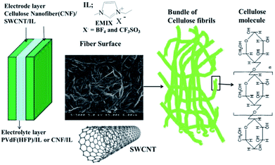 | ||
| Fig. 1 The configuration of the CNF/SWCNT/IL actuator and the molecular structures of the CNF, SWCNT and ILs employed in this study. | ||
Preparation of the actuator film
Fig. 1 depicts the configuration of the CNF/SWCNT/IL actuators that have been developed in this study. Typically, the CNF/SWCNT/IL electrode layer (80/50/120) comprises 32 wt% CNF, 20 wt% SWCNT and 48 wt% IL. All the layers were individually prepared by mixing LB or BB (either of them with 800 mg of 10 wt%), SWCMT (50 mg) and EMI[BF4] or EMI[CF3SO3] (120 mg) in H2O (9 mL); this mixture was ultrasonically dispersed for more than 5 h. Subsequently, the resulting mixture (2.4 mL), which was gelatinous, was cast in a Teflon mould according to the aforementioned steps to obtain a 150–175 μm thick electrode film.The gel electrolyte layers were fabricated by casting a solution (0.3 mL) comprising either of the two ILs and PVdF(HFP) (100 mg each) that was later mixed with MP (1 mL) and PC (250 mg) in a Teflon mould (25 × 25 mm2). The solvent was subsequently evaporated and completely removed in vacuo at 80 °C. The thickness of the resulting gel electrolyte films was 20–30 μm. The CNF/IL electrolyte layer (50/150) comprised 25 wt% CNF and 75 wt% IL. The layers were individually prepared by mixing LB or BB (either of them with 500 mg of 10 wt%) and EMI[BF4] or EMI[CF3SO3] (150 mg) in H2O (9 mL); this mixture was ultrasonically dispersed. Subsequently, the resulting mixture (2.4 mL) was cast in a Teflon mould according to the procedures outlined above to obtain an electrode film with a thickness of 50–60 μm. Finally, the electrode/electrolyte layers comprising the same IL were hot-pressed to obtain a 280–330 μm thick actuator film; this thickness was less than the combined thicknesses of its component layers because each layer was hot-pressed.
Displacement measurement
The displacement measurements were performed according to those that have been conducted in a previous study.25 The following equation transforms the measured displacement δ into a strain difference between two bucky gel electrode layers (ε) by assuming that the cross-sections were planar at any position along the actuator (i.e. no distortion occurred in the cross section):| ε = 2dδ/(L2 + δ2), | (1) |
Characterisation of the electrode and electrolyte
The electrical conductivity of the gel electrolyte layer was determined by measuring the impedance using a Solartron 1250 Impedance Analyzer. The double-layer capacitance of the polymer-supported bucky gel electrode (7 mm diameter) was estimated via cyclic voltammetry using a potentiostat in a two-electrode configuration (Hokuto Denko, HSV-100). Further, the electrical conductivity of the electrodes was evaluated using the four-probe DC current method. The Young's moduli for the electrodes were estimated from the stress–strain curves using a thermal stress–strain instrument (Seiko, TMA/SS 6000). The morphological differences in the electrode films were observed by acquiring the images using HITACHI S-5000 FESEM.Results and discussion
We initially examined the ionic conductivities κ (= thickness/(R × area)) for a range of ILs in both the CNF/IL gel and the PVdF(HFP)/IL gel. As presented in Table 1, the ionic conductivities ranged between approximately 3.3–4.6 and 2.8–4.4 mS cm−1, and little correlation was observed between the values for the gel and pure ILs. The ionic conductivity of the gel electrolyte layer was observed to be dependent on the IL species. Table 2 compares the ionic conductivities (mS cm−1) for the CNF/IL electrolytes with different ratios. Further, in this case, the ionic conductivity of the gel electrolyte layer was dependent on the ratio of the CNF/IL electrolytes.| IL | LB/IL = 3 | BB/IL = 3 | LB/IL = 4 | BB/IL = 4 |
|---|---|---|---|---|
| EMI[BF4] | 3.9 | 4.6 | 7.2 | 9.6 |
| EMI[CF3SO3] | 3.3 | 3.9 | 6.3 | 6.4 |
Table 3 presents the values of the double-layer capacitance C [gravimetric capacitance of the SWCNTs, CSWCNT = C1/(weight of the SWCNTs)] of the CNF/SWCNT/IL electrodes and the PVdF(HFP) or CNF/IL electrolyte. At a slow sweep rate of 1 mV s−1, the specific capacitance of the CNF/SWCNT/IL electrodes and the PVdF(HFP)/IL electrolyte became 32–35 F g−1, and the double-layer capacitance of the CNF/SWCNT/EMI[BF4] electrodes was slightly larger than that of the CNF/SWCNT/EMI[CF3SO3] electrode. Therefore, the double-layer capacitance depended on the IL species that were present in the system. In contrast, the double-layer capacitances of the CNF/SWCNT/IL electrodes and CNF/IL electrolyte were approximately 30–32 F g−1, and the double-layer capacitance did not depend on the IL species present in the system. These results indicated that the double-layer capacitance of the PVdF(HFP)/IL electrolyte was slightly larger than that of the CNF/IL electrolyte; further, these results considered the effect of the PVdF(HFP)/IL electrolyte or the CNF/IL electrolyte to be relatively small.
| IL | LB/PVdF(HFP) | BB/PVdF(HFP) | LB/LB | BB/BB |
|---|---|---|---|---|
| EMI[BF4] | 35.1 | 35.1 | 32.3 | 29.8 |
| EMI[CF3SO3] | 33.2 | 31.5 | 31.8 | 29.5 |
Table 4 presents the electrical conductivities of CNF or PVdF(HFP)/SWCNT/IL. More specifically, the electrical conductivities of the CNF/SWCNT/IL electrodes became 0.36–0.98 S cm−1, and the electrical conductivity of the LB/SWCNT/IL electrodes was larger than that of the BB/SWCNT/IL electrodes; furthermore, the electrical conductivity of the CNF/SWCNT/EMI[BF4] electrodes was slightly larger than that of CNF/SWCNT/EMI[CF3SO3]. Thus, the electrical conductivity of this gel electrode layer appeared to be dependent on the CNF and IL species, whereas that of the PVdF(HFP)/SWCNT/IL electrode was 14–18 S cm−1. Notably, these values may represent the non-formation (a part) for an open mesoporous network of SWCNT for all the CNF/SWCNT/IL electrodes.
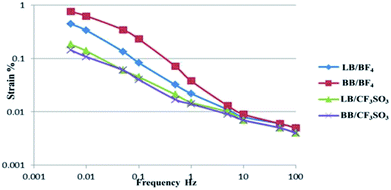
The strains (ε, %) produced in the actuators as a function of the applied voltage frequency (±2 V, triangular waveform) for the CNF/SWCNT/IL electrode and the PVdF(HFP)/IL electrolyte were further evaluated; the corresponding results are presented in Fig. 2. As depicted, strain was clearly dependent on the voltage frequency.
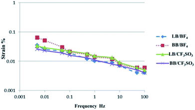
The strains (ε, %) produced in the actuators as a function of the frequency of the applied voltage (±2 V, triangular waveform) were examined for the CNF/SWCNT/IL electrode and CNF/IL electrolyte; Fig. 3 depicts the corresponding results. As depicted, strain was clearly dependent on the voltage frequency. The PVdF(HFP)/IL electrolyte actuators (Fig. 2) exhibited a higher strain (>10 Hz) when compared to that exhibited by the CNF/IL electrolyte actuators (Fig. 3) because of which both the CNF/SWCNT/IL electrode and the PVdF(HFP)/IL electrolyte surfaces may be considered to display better adhesion than those displayed by the CNF/SWCNT/IL electrode and the CNF/IL electrolyte surfaces.9–11
In addition, the CNF/SWCNT/IL electrode and the PVdF(HFP)/IL electrolyte actuators was stable in air for at least 10![[thin space (1/6-em)]](https://www.rsc.org/images/entities/char_2009.gif) 000 cycles. Therefore, it can be considered that the CNF/IL gel hybrid actuator based on SWCNTs will have a long operating life in air.19,25
000 cycles. Therefore, it can be considered that the CNF/IL gel hybrid actuator based on SWCNTs will have a long operating life in air.19,25
Table 5 presents the maximum strain calculated from the peak-to-peak displacements of the CNF/SWCNT/IL electrode and the PVdF(HFP) or CNF/IL electrolyte actuators. As indicated, the maximum strain was 0.44–0.76% for the PVdF(HFP)/IL electrolyte actuators. More specifically, the maximum strain of the CNF/SWCNT/EMI[BF4] electrodes was larger than that of the CNF/SWCNT/EMI[CF3SO3] electrodes. Thus, the maximum strain of this gel electrode layer was dependent on the IL species. Thus, the Young's modulus for the CNF/SWCNT/EMI[CF3SO3] actuator can be larger than that of the CNF/SWCNT/EMI[BF4] actuator. The maximum strain was 0.03–0.06% for the CNF/SWCNT/IL electrode and the CNF/IL electrolyte actuators. Thus, the maximum strain of this gel electrode layer was independent of the CNF and IL species. The aforementioned results indicate that the PVdF(HFP)/IL electrolyte actuators can exhibit better performance than that exhibited by the actuators with the CNF/IL electrolyte. Consequently, the surface of the CNF/SWCNT/IL electrode and the PVdF(HFP)/IL electrolyte may be considered to display better adhesion than that displayed by the CNF/SWCNT/IL electrode and the CNF/IL electrolyte.9–11
| IL | LB/PVdF(HFP) | BB/PVdF(HFP) | LB/LB | BB/BB |
|---|---|---|---|---|
| EMI[BF4] | 0.44 | 0.76 | 0.04 | 0.06 |
| EMI[CF3SO3] | 0.18 | 0.14 | 0.03 | 0.03 |
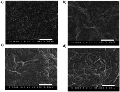
Fig. 4 denotes the scanning electron microscopy (SEM) micrographs (5.0 kV, magnification: 5000×) of (a) PVdF(HFP)/SWCNT/EMI[BF4] = 80/50/120, (b) LB/SWCNT/EMI[BF4] = 80/50/120, (c) BB/SWCNT/EMI[BF4] = 80/50/120 electrode layers and (d) BB/EMI[BF4] = 100/200 electrolyte layers; Fig. 4(b)–(d) denote that the electrode and electrolyte morphologies are a network of highly entangled CNFs.
Fig. S1† depicts the SEM micrographs (20.0 kV) of PVdF(HFP)/SWCNT/EMI[BF4] = 80/50/120 for (a) magnification = 5000× and (b) magnification = 50![[thin space (1/6-em)]](https://www.rsc.org/images/entities/char_2009.gif) 000×. Fig. S1(b)† reveals that the electrode morphologies are a network of open pores formed by highly entangled SWCNTs.33,34 Fig. 4(a) and S1(a)† denote that electrode morphologies are a network formed by highly entangled SWCNTs, and Fig. 4(b) and (c) denote that electrode morphologies are a network formed by highly entangled CNFs and SWCNTs.
000×. Fig. S1(b)† reveals that the electrode morphologies are a network of open pores formed by highly entangled SWCNTs.33,34 Fig. 4(a) and S1(a)† denote that electrode morphologies are a network formed by highly entangled SWCNTs, and Fig. 4(b) and (c) denote that electrode morphologies are a network formed by highly entangled CNFs and SWCNTs.
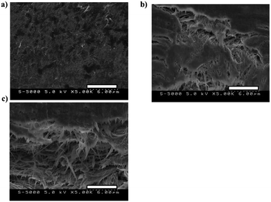
Fig. 5 depicts the cross-sectional SEM micrographs (5.0 kV, magnification: 5000×) for (a) PVdF(HFP)/SWCNT/EMI[BF4] = 80/50/120, (b) LB/SWCNT/EMI[BF4] = 80/50/120 and (c) BB/SWCNT/EMI[BF4] = 80/50/120 electrode layers; Fig. 5(a) denotes that electrode morphologies are a network formed by highly entangled SWCNTs.33,34 Fig. 5(b) and (c) denote that electrode morphologies are a network formed by highly entangled CNFs and SWCNTs.
Table 6 compares the Young's moduli of the different actuators that have been investigated herein. The Young's moduli of CNF/SWCNT/EMI[BF4] and CNF/SWCNT/EMI[CF3SO3] actuators were 133–184 and 233–258 MPa, respectively; these values were consistent with those of the network formed by highly entangled CNFs and SWCNTs. In addition, the Young's modulus of the CNF/SWCNT/EMI[CF3SO3] electrode was found to be larger than that of the CNF/SWCNT/EMI[BF4] electrode. This indicated that the Young's moduli of polymer-based actuators are dependent on the type of IL that was employed and suggested that the maximum strain of the CNF/SWCNT/EMI[BF4] electrodes was larger than that of the CNF/SWCNT/EMI[CF3SO3] electrodes.
| IL | LB | BB |
|---|---|---|
| EMI[BF4] | 186 | 133 |
| EMI[CF3SO3] | 233 | 258 |
Table 7 presents the maximum stress (σ) generated in the polymer-supported bucky gel actuators, as calculated using Hooke's law (i.e. σ = Y × εmax, where εmax denotes the maximum strain and Y denotes the Young's modulus). The maximum generated stress (σ) in the PVdF(HFP)/IL electrolyte actuators ranged from 0.36 to 1.01 MPa. Specifically, the maximum generated stress of the CNF/SWCNT/EMI[BF4] electrodes was larger than that of the CNF/SWCNT/EMI[CF3SO3] electrodes. Thus, the maximum generated stress of this gel electrode layer appeared to be dependent on the IL species. In particular, the maximum generated stress of the actuator containing the CNF/SWCNT/EMI[BF4] electrode was approximately 2–3 times higher than that of the actuator containing the CNF/SWCNT/EMI[CF3SO3] electrode. While the maximum generated stresses (σ) ranged from 0.07 to 0.08 MPa for the CNF/SWCNT/IL electrode and the CNF/IL electrolyte actuators, the maximum generated stress of this particular gel electrode layer appeared to be independent of the CNF and IL species. The aforementioned results indicated that the actuators with the PVdF(HFP)/IL electrolyte exhibited a significantly better performance than that exhibited by the actuators with the CNF/IL electrolyte. These results also indicated that the CNF/SWCNT/IL electrode and the PVdF(HFP)/IL electrolyte actuators outperformed the CNF/SWCNT/IL electrode and the CNF/IL electrolyte actuators.
| IL | LB/PVdF(HFP) | BB/PVdF(HFP) | LB/LB | BB/BB |
|---|---|---|---|---|
| EMI[BF4] | 0.81 | 1.01 | 0.07 | 0.08 |
| EMI[CF3SO3] | 0.42 | 0.36 | 0.07 | 0.07 |
The proposed mechanism explains the actuator bending motion.20 Cations and anions are transferred from the gel electrolyte layer to the cathode and anode layers, respectively, when voltage is applied across the two electrode layers. This mechanism results in the formation of an electrical double layer with nanotubes that are negatively and positively charged; in addition, the associated transportation of ions results in the cathode and anode layers experiencing shrinkage and swelling, respectively (Fig. 6).
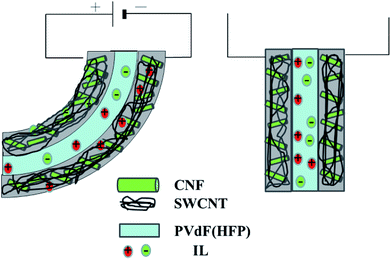 | ||
| Fig. 6 Schematic of the response model used for the CNF/SWCNT/IL electrode and the PVdF(HFP)/IL electrolyte actuators. | ||
The voltage–current and voltage–displacement correlations demonstrated by the bucky gel actuators in response to the triangular waveform voltage at different frequencies were previously evaluated,21 and the low-frequency strain limit as well as the response time constant were predicted. The frequency dependence of the displacement response was measured for the PVdF(HFP)/SWCNT/IL electrode and the PVdF(HFP)/IL electrolyte actuators, which could be successfully simulated using a double-layer charging kinetic model. The results yielded the strain in the low-frequency limit, which was related to the electromechanical mechanism involved in the process, in addition to the time constant of the response, which was represented by that of an equivalent circuit comprising a series combination of ionic and electronic resistances and double-layer capacitance.
In Fig. 7(a), the BB/SWCNT/EMI[BF4] electrodes and PVdF(HFP)/EMI[BF4] electrolyte actuators clearly indicate that curve B accurately reproduced the frequency dependence of the strain, similar to that reproduced by the double-layer charging kinetic model when the double-layer capacitance and the resistance of both the electrode and the gel electrolyte were considered. Similar results were obtained for the LB/SWCNT/EMI[BF4] or CNF/SWCNT/EMI[CF3SO3] electrodes and the PVdF(HFP)/IL electrolyte actuators. Further, the response of the CNF/SWCNT/IL electrodes and the PVdF(HFP)/IL electrolyte actuators could be improved by fabricating a gel electrode and electrolyte with a high conductivity value (see ESI† for details).
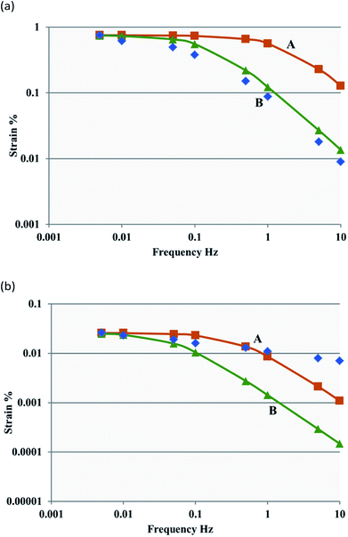 | ||
| Fig. 7 Measured (blue dots) and simulated (green and orange curves) data showing the frequency dependence of the strain for the CNF/SWCNT/IL electrodes and the PVdF(HFP)/IL or CNF/IL electrolyte actuators. Curves A and B were calculated using the equivalent circuits shown in Fig. S2(b) and S2(c),† respectively. (a) The BB/SWCNT/EMI[BF4] electrodes and PVdF(HFP)/EMI[BF4] electrolyte actuators and (b) the BB/SWCNT/EMI[CF3SO3] electrodes and BB/EMI[CF3SO3] electrolyte actuators. | ||
The BB/SWCNT/EMI[CF3SO3] electrodes and BB/EMI[CF3SO3] electrolyte actuators in Fig. 7(b) clearly indicate that the frequency dependence of the strain is well reproduced by curve A (>1 Hz). Fig. 7(b) also clearly shows that the frequency dependence of the strain was effectively reproduced by the double-layer charging kinetic model when the double-layer capacitance and the gel electrolyte resistance (>1 Hz) were considered, which differed from that observed in the CNF/SWCNT/IL electrodes and PVdF(HFP)/IL electrolyte actuators, wherein the electrode and gel electrolyte resistances were considered. Similar results were obtained for the LB/SWCNT/EMI[CF3SO3] electrodes or the CNF/SWCNT/EMI[BF4] electrodes and the CNF/IL electrolyte actuators. Similar to the previously discussed configuration, the response of the CNF/SWCNT/IL electrodes and the CNF/IL electrolyte actuators could be improved by fabricating a gel electrolyte with a high conductivity value, which was different from that of the CNF/SWCNT/IL electrodes and the PVdF(HFP)/IL electrolyte actuators (see ESI† for details).
Conclusions
In this study, new actuators were developed using the CNF/SWCNT/IL structures. Further, the electrochemical and electromechanical properties of the CNF/IL gel hybrid actuators based on SWCNTs were examined.The PVdF(HFP)/IL electrolyte actuators exhibited a higher strain when compared with that exhibited by the CNF/IL electrolyte actuators. The maximum strain of the gel electrode layer was dependent on the IL species in the CNF/SWCNT/IL electrode and the PVdF(HFP)/IL electrolyte actuators; the maximum strain appeared to be independent of the CNF and IL species in the CNF/SWCNT/IL electrode and the CNF/IL electrolyte actuators. The CNF/SWCNT/IL electrode denotes a network formed by highly entangled CNFs and SWCNTs and is dependent on the type of IL that has been employed. The maximum generated stress (σ) of the CNF/SWCNT/IL electrode and PVdF(HFP)/IL electrolyte actuators appeared to be dependent on the IL species, whereas the maximum generated stress (σ) of the CNF/SWCNT/IL electrode and the CNF/IL electrolyte actuators appeared to be independent of the CNF and IL species. These results also indicated that the CNF/SWCNT/IL electrode and the PVdF(HFP)/IL electrolyte actuators performed significantly better than the CNF/SWCNT/IL electrode and the CNF/IL electrolyte actuators. Thus, employing the PVdF(HFP)/IL electrolyte to maximise the strain and generated stress shows considerable promise for use in real-world applications.
The CNF/SWCNT/IL electrodes and the PVdF(HFP)/IL electrolyte actuators denote that the frequency dependence of strain was reproduced using the double-layer charging kinetic model when the resistances of both the electrode and the gel electrolyte were considered, whereas the CNF/SWCNT/IL electrodes and the CNF/IL electrolyte actuators clearly indicated that the frequency dependence of the strain was reproduced using the double-layer charging kinetic model only when the gel electrolyte resistance (>1 Hz) was exclusively considered. Based on the results of this study, the CNF/SWCNT/IL electrodes and the PVdF(HFP)/IL electrolyte actuators exhibit good promise for usage as electrochemical materials in various applications, including wearable devices and energy-conversion devices.
Conflicts of interest
There are no conflicts to declare.Acknowledgements
This research was funded in part by the Japan Society for The Promotion of Science (JSPS) under a KAKENHI Grant-in Aid for Scientific Research C (17K05983).Notes and references
- D. R. Paul and L. M. Robeson, Polymer, 2008, 49, 3187–3204 CrossRef CAS.
- R. Rusli and S. J. Eichhorn, Appl. Phys. Lett., 2008, 93, 033111 CrossRef.
- A. Šturcová, G. R. Davies and S. J. Eichhorn, Biomacromolecules, 2005, 6, 1055–1061 CrossRef PubMed.
- H. M. Azeredo, Food Res. Int., 2009, 42, 1240–1253 CrossRef.
- A. Isogai, T. Saito and H. Fukuzumi, Nanoscale, 2011, 3, 71–85 RSC.
- L. C. Zhang, X. Sun, Z. Hu, C. C. Yuan and C. H. Chen, J. Power Sources, 2012, 204, 149–154 CrossRef CAS.
- A. Chiappone, J. Nair, C. Gerbaldi, L. Jabbour, R. Bongiovanni, E. Zeno, D. Beneventi and N. Penazzi, J. Power Sources, 2011, 196, 10280–10288 CrossRef CAS.
- A. M. Stephan and D. Teeters, J. Power Sources, 2003, 119, 460–464 CrossRef.
- A. Magistris, E. Quartarone, P. Mustarelli, Y. Saito and H. Kataoka, Solid State Ionics, 2002, 152, 347–354 CrossRef.
- Q. Shi, M. Yu, X. Zhou, Y. Yan and C. Wan, J. Power Sources, 2002, 103, 286–292 CrossRef CAS.
- S. S. Zhang, K. Xu, D. L. Foster, M. H. Ervin and T. R. Jow, J. Power Sources, 2004, 125, 114–118 CrossRef CAS.
- R. Mejri, J. C. Dias, S. B. Hentati, M. S. Martins, C. M. Costa and S. Lanceros-Mendez, J. Non-Cryst. Solids, 2016, 453, 8–15 CrossRef CAS.
- R. Mejri, J. C. Dias, S. B. Hentati, G. Botelho, J. M. S. S. Esperança, C. M. Costa and S. Lanceros-Mendez, Eur. Polym. J., 2016, 85, 445–451 CrossRef CAS.
- H. Nakagawa, S. Izuchi, K. Kuwana, T. Nukuda and Y. Aihara, J. Electrochem. Soc., 2003, 150, A695–A700 CrossRef CAS.
- B. Garcia, S. Lavallée, G. Perron, C. Michot and M. Armand, Electrochim. Acta, 2004, 49, 4583–4588 CrossRef CAS.
- Directions for development of the field of Electroactive Polymer (EAP). ed. Y. Bar-Cohen, SPIE Press, Washington, DC, 2011 Search PubMed.
- E. Smela, Adv. Mater., 2003, 15, 481–494 CrossRef CAS.
- M. Shahinpoor, Electrochim. Acta, 2003, 48, 2343–2353 CrossRef CAS.
- T. Fukushima, K. Asaka, A. Kosaka and T. Aida, Angew. Chem., Int. Ed., 2005, 44, 2410–2413 CrossRef CAS PubMed.
- K. Mukai, K. Asaka, K. Kiyohara, T. Sugino, I. Takeuchi, T. Fukushima and T. Aida, Electrochim. Acta, 2008, 53, 5555–5562 CrossRef CAS.
- I. Takeuchi, K. Asaka, K. Kiyohara, T. Sugino, K. Mukai, T. Fukushima and T. Aida, Electrochim. Acta, 2009, 53, 1762–1768 CrossRef.
- T. Fukushima, A. Kosaka, Y. Ishimura, T. Yamamoto, T. Takigawa, N. Ishii and T. Aida, Science, 2003, 300, 2072–2074 CrossRef CAS PubMed.
- W. Lu, A. G. Fadeev, B. Qi, E. Smela, B. R. Mattes, J. Ding, G. M. Spinks, J. Mazurkiewicz, D. Zhou, G. G. Wallace, D. R. MacFarlane, S. A. Forsyth and M. Forsyth, Science, 2002, 297, 983–987 CrossRef CAS PubMed.
- N. Terasawa, I. Takeuchi and H. Matsumoto, Sens. Actuators, B, 2009, 139, 624–630 CrossRef CAS.
- N. Terasawa, N. Ono, Y. Hayakawa, K. Mukai, T. Koga, H. Higashi and K. Asaka, Sens. Actuators, B, 2011, 160, 161–167 CrossRef CAS.
- L. Lu, J. Liu, Y. Hu, Y. Zhang and W. Chen, Adv. Mater., 2013, 25, 1270–1274 CrossRef CAS PubMed.
- L. Kong and W. Chen, Adv. Mater., 2014, 26, 1025–1043 CrossRef CAS PubMed.
- G. Wu, Y. Hu, Y. Liu, J. Zhao, X. Chen, V. Whoehling, C. Plesse, G. T. Nguyen, F. Vidal and W. Chen, Nat. Commun., 2015, 6, 7258 CrossRef CAS PubMed.
- V. Palmre, J. Torop, M. Arulepp, T. Sugino, K. Asaka, A. Jänes, E. Lust and A. Aabloo, Carbon, 2012, 50, 4351–4358 CrossRef CAS.
- D. Nevstrueva, K. Murashko, V. Vunder, A. Aabloo, A. Pihlajamäki, M. Mänttäri, J. Pyrhönen, T. Koiranen and J. Torop, Colloids Surf., B, 2018, 161, 244–251 CrossRef CAS PubMed.
- Q. Pei and O. Inganas, J. Phys. Chem., 1992, 96, 10507–10514 CrossRef CAS.
- N. Terasawa and K. Asaka, Langmuir, 2016, 32, 7210–7218 CrossRef CAS PubMed.
- Y. Zhang, J. Li, L. Niu, S. Dong and A. Ivaska, Langmuir, 2005, 21, 4797–4800 CrossRef CAS PubMed.
- R. H. Baughman, C. Cui, A. A. Zakhidov, Z. Iqbal, J. N. Barisci, G. M. Spinks, G. G. Wallace, A. Mazzoldi, D. DeRossi, A. G. Rinzler, O. Jaschinski, S. Roth and M. Keertesz, Science, 1999, 284, 1340–1344 CrossRef CAS PubMed.
Footnote |
| † Electronic supplementary information (ESI) available. See DOI: 10.1039/c8ra10221j |
| This journal is © The Royal Society of Chemistry 2019 |

