 Open Access Article
One-step sulfuration synthesis of hierarchical NiCo2S4@NiCo2S4 nanotube/nanosheet arrays on carbon cloth as advanced electrodes for high-performance flexible solid-state hybrid supercapacitors†
Jinlei Xie,
Yefeng Yang *,
Geng Li,
Hanchun Xia,
Peijia Wang,
Peiheng Sun,
Xiaolong Li,
Haoran Cai
 and
Jie Xiong
Department of Materials Engineering, College of Materials and Textiles, Zhejiang Sci-Tech University, Hangzhou 310018, P. R. China. E-mail: yangyf@zstu.edu.cn; Tel: +86-571-8684-5569
First published on 22nd January 2019
Abstract
To obtain high-performance hybrid supercapacitors (HSCs), a new class of battery-type electrode materials with hierarchical core/shell structure, high conductivity and rich porosity are needed. Herein, we propose a facile one-step sulfuration approach to achieve the fabrication of hierarchical NiCo2S4@NiCo2S4 hybrid nanotube/nanosheet arrays (NTSAs) on carbon cloth, by taking hydrothermally grown Ni–Co precursor@Ni–Co precursor nanowire/nanosheet arrays (NWSAs) as the starting templates. The optimized electrode of NiCo2S4@NiCo2S4 hybrid NTSAs demonstrates an enhanced areal capacity of 245 μA h cm−2 at 2 mA cm−2 with outstanding rate capability (73% from 2 to 20 mA cm−2) and cycling stability (86% at 10 mA cm−2 over 3000 cycles). In addition, flexible solid-state HSC devices are assembled by using NiCo2S4@NiCo2S4 hybrid NTSAs and activated carbon as the positive and negative electrodes, respectively, which manifest a maximum volumetric energy density of 1.03 mW h cm−3 at a power density of 11.4 mW cm−3, with excellent cycling stability. Our work indicates the feasibility of designing and fabricating core/shell structured metal sulfides through such a facile one-step sulfuration process and the great potential of these materials as advanced electrodes for high-performance HSC devices.
Introduction
Due to the fast development of hybrid electrical vehicles (HEVs), portable and wearable electronics, there has been increasing demand for efficient and renewable energy storage devices.1–3 As a good complement to rechargeable lithium-ion batteries (LIBs), supercapacitors have attracted intensive research attention in view of their many appealing advantages, including high power density, fast charge–discharge capability, long lifespan, high safety and environmental compatibility.4–6 Hybrid supercapacitors (HSCs), which are typically comprised of a faradaic battery-type electrode and an electrical double-layer capacitive (EDLC) electrode as the energy and power sources, respectively, have emerged as one of the most promising candidates, since they can combine the merits of both electrodes with improved energy density and enlarged output voltage window.7–9 As the key component of HSC devices, various battery-type electrode materials, including transition metal oxides (Co3O4, NiCo2O4, CuCo2O4),10–16 hydroxides (Ni(OH)2, Ni–Mn LDH, Ni–Co LDH) and their composites,17–20 have been widely explored owing to their high theoretical capacity, natural abundance and low cost. However, the typically low conductivity of these materials has greatly restricted their improvement of rate capability and durability. In this regard, nickel cobalt sulfide (NiCo2S4), as a ternary transition metal sulfide, has been recently investigated as a new kind of battery-type electrode for HSC devices with better electrochemical performance, since it is expected to offer much higher electrical conductivity and richer redox reactions than the corresponding single component oxides and sulfides.21–31It is worth noting that the diffusion depth of electrolyte into electrode materials is usually limited (only ∼20 nm),32,33 and only the surface part can be effectively involved in the energy storage process and contribute to the total capacity. In order to improve the utilization of electrode materials and significantly boost the energy storage efficiency, one feasible and efficient strategy is to design and fabricate hierarchical tubular nanostructure arrays in core/shell configuration with large surface area directly on conductive substrates. In the past few years, several groups have focused on this issue and reported the fabrication of core/shell hybrid electrodes based on Ni–Co sulfide nanotube arrays (NTAs) for HSC devices. For instance, Xiao et al. demonstrated the fabrication of NiCo2S4@CoxNi1−x(OH)2 nanotube/nanosheet arrays (NTSAs) on carbon fiber paper through the electrodeposition of shell materials on NiCo2S4 backbones, which exhibited an areal capacity of 397 μA h cm−2 at a current density of 4 mA cm−2 and a rate capability of 84% at 20 mA cm−2.34 Besides, Xie et al. reported the electrodeposition growth of CoSx nanosheets on the surface of NiCo2S4 NTAs on Ni foam, and the resulting NiCo2S4@CoSx hybrid electrode delivered an areal capacity of 593 μA h cm−2 at 5 mA cm−2 and a capacity retention of 47% at 50 mA cm−2.35 In another work, Lai and co-workers described the successful coating of Co0.85Se nanosheets via an electrodeposition method on CoNi2S4 NTAs supported on graphene foam, and a high areal capacity of 656 μA h cm−2 was achieved at 1 mA cm−2 with a retention of 50% at 20 mA cm−2.36 Very recently, Zhao et al. fabricated hierarchical core/shell structured NiCo2S4@Ni(OH)2@PPy NTSAs grown on Ni foam through the combined methods of multi-step hydrothermal reaction and subsequent polymerization process, showing an extremely high areal capacity of 1012 μA h cm−2 at 5 mA cm−2 with a cycling stability of 96% over 3000 cycles.37 Although great progress has been made in this field, many of these reported methods still require complicated and time-consuming processes. As a consequence, it is highly essential to develop new simple and green methods to realize the facile construction of NiCo2S4 based hierarchical tubular nanostructures with precisely controlled morphology and enhanced electrochemical properties for HSC devices.
Herein, we present a versatile synthetic strategy for the fabrication of NiCo2S4@NiCo2S4 core/shell hybrid NTSAs on carbon cloth as advanced electrodes for supercapacitors. To the best of our knowledge, there has been little literature on core/shell hybrid electrodes integrating metal sulfide materials on the backbones of NiCo2S4 NTAs on highly flexible and conductive substrates. In this work, Ni–Co precursor@Ni–Co precursor nanowire/nanosheet arrays (NWSAs) grown on carbon cloth by facile hydrothermal reactions are judiciously used as the starting templates, and then simultaneously transformed into the desired NiCo2S4@NiCo2S4 core/shell hybrid NTSAs via a one-step sulfuration process through anion exchange reaction with S2− ions. The resulting three-dimensional (3D) hierarchical nanostructures possess unique hollow tubular structure with interconnected networks and rich porosity, which can enable the full utilization of electroactive materials especially the interior parts, and promote the fast ion diffusion and electron transport in the integrated system. Benefiting from these features, the optimized NiCo2S4@NiCo2S4 hybrid electrode delivers an enhanced areal capacity of 245 μA h cm−2 at 2 mA cm−2, a good rate capability of 73% from 2 to 20 mA cm−2, and a remarkable cycling stability of 86% at 10 mA cm−2 over 3000 cycles. Furthermore, flexible solid-state HSC devices are assembled by employing the NiCo2S4@NiCo2S4 hybrid NTSAs and activated carbon (AC) as the positive and negative electrode, respectively, which achieves a maximum volumetric energy density of 1.03 mW h cm−3 at a power density of 11.4 mW cm−3, as well as an excellent cycling stability.
Experimental
Synthesis of Ni–Co precursor nanowire arrays (NWAs) on carbon cloth
All the chemicals with analytical grade were commercially available from Shanghai Sinopharm Chemical Reagents and used without further purification. The Ni–Co precursor NWAs grown on carbon cloth were synthesized by a slightly modified method reported in our previous work.38 Prior to the synthesis, the carbon cloth substrate was successively treated in acetone, ethanol and deionized (DI) water by ultrasonication. Afterwards, 1 mmol of Ni(NO3)2·6H2O, 2 mmol of Co(NO3)2·6H2O and 12 mmol of urea were added into 80 mL of DI water. The resulting transparent solution and a piece of carbon cloth substrate were together transferred into a 100 mL stainless steel autoclave, which was sealed and kept at 120 °C for 6 h before being cooled down to room temperature. The Ni–Co precursor NWAs were rinsed several times with DI water and dried in air overnight for further use.One-step sulfuration synthesis of NiCo2S4@NiCo2S4 hybrid nanotube/nanosheet arrays (NTSAs)
The hierarchical NiCo2S4@NiCo2S4 hybrid NTSAs were synthesized through a facile secondary hydrothermal growth of Ni–Co precursor nanosheets on the surface of Ni–Co precursor NWAs, followed by a one-step sulfuration process. Typically, 0.5 mmol of Ni(NO3)2·6H2O, 1 mmol of Co(NO3)2·6H2O and 4 mmol of tetramethyleneamine (HMT) were dissolved in 70 mL of methanol under vigorous stirring and then transferred into a 100 mL autoclave. The Ni–Co precursor NWAs supported on carbon cloth were immersed in the above homogeneous solution and then the autoclave was maintained at 180 °C for 2 h to grow Ni–Co precursor nanosheets on the surface of Ni–Co precursor NWAs, leading to the formation of core/shell structured Ni–Co precursor@Ni–Co precursor NWSAs. The resulting sample was rinsed with DI water and dried in air. In the next step, the obtained sample was loaded in an autoclave containing an aqueous solution of Na2S·9H2O (0.03 M) and further treated by a one-step anion exchange reaction with S2− ions at 120 °C for 9 h. Finally, the desired hierarchical NiCo2S4@NiCo2S4 hybrid NTSAs were obtained, which were washed thoroughly with DI water to remove the surface impurities and dried in vacuum overnight. The mass loading of NiCo2S4@NiCo2S4 NTSAs on carbon cloth was calculated to be ca. 1.20 mg cm−2. For comparison, NiCo2S4 nanotube arrays (NTAs) and NiCo2S4 nanosheet arrays (NSAs) were also prepared on carbon cloth using similar synthetic routes with a mass loading of 0.70 mg cm−2 and 0.38 mg cm−2, respectively, through the direct sulfuration of Ni–Co precursor NWAs and Ni–Co precursor NSAs, respectively.Materials characterization
The X-ray diffraction (XRD) patterns were obtained on a Bruker D8 Advance diffractometer (40 kV, 40 mA) with Cu Kα radiation (λ = 1.5406 Å). The morphology and structure of the samples were investigated by field-emission scanning electron microscope (FE-SEM, Hitachi S4800), transmission electron microscope (TEM) and high-resolution TEM (HRTEM) taken on a FEI Tecnai F20 operated at 200 kV, respectively. The energy-dispersive X-ray spectrometry (EDS) mapping was carried out on Tecnai F20 under STEM mode with a high-angle annular dark-field (HAADF) detector, and the data were processed by TIA software. The X-ray photoelectron spectroscopy (XPS) measurements were conducted on a Thermo ESCALAB-250 spectrometer with a monochromatic Al Kα radiation (1486.6 eV).Electrochemical measurements
Electrochemical measurements including cyclic voltammetry (CV), galvanostatic charge–discharge (GCD) and electrochemical impedance spectroscopy (EIS) were carried out on a CHI760E electrochemical workstation, while the cycling stability was tested on a LAND battery system. For single electrodes, the electrochemical measurements were conducted at room temperature in a three-electrode configuration with 3 M KOH solution as the electrolyte. The as-prepared samples on carbon cloth were directly utilized as the working electrode, with Pt foil and saturated calomel electrode (SCE) acting as the counter electrode and reference electrode, respectively.The areal and specific capacities of battery-type electrodes were calculated according to the following equations:
| Qa = It/S |
| Qs = It/m |
Fabrication of flexible solid-state HSC devices
Flexible solid-state HSC devices were assembled by employing the as-prepared NiCo2S4@NiCo2S4 NTSAs obtained from the one-step sulfuration method as the positive electrode and activated carbon (AC) as the negative electrode (denoted as NiCo2S4@NiCo2S4//AC). Specifically, the negative electrode was prepared by mixing AC, acetylene black and polyvinylidene fluoride (PVDF) with a mass ratio of 8![[thin space (1/6-em)]](https://www.rsc.org/images/entities/char_2009.gif) :
:![[thin space (1/6-em)]](https://www.rsc.org/images/entities/char_2009.gif) 1
1![[thin space (1/6-em)]](https://www.rsc.org/images/entities/char_2009.gif) :
:![[thin space (1/6-em)]](https://www.rsc.org/images/entities/char_2009.gif) 1 in N-methyl-2-pyrrolidone (NMP). The obtained slurry was then coated onto a piece of carbon cloth and dried at 80 °C under vacuum overnight. To assemble the flexible solid-state HSC device, a gel of polyvinyl alcohol (PVA)/KOH was prepared by mixing 6 g PVA and 3 g KOH in 80 mL DI water under 90 °C and then utilized as the electrolyte, while a piece of electrolyte-soaked cellulose filter paper was taken as the separator between the two electrodes. The assembled solid-state HSC devices were carefully encapsulated by plastic films to avoid the exposure of electrolyte to air.
1 in N-methyl-2-pyrrolidone (NMP). The obtained slurry was then coated onto a piece of carbon cloth and dried at 80 °C under vacuum overnight. To assemble the flexible solid-state HSC device, a gel of polyvinyl alcohol (PVA)/KOH was prepared by mixing 6 g PVA and 3 g KOH in 80 mL DI water under 90 °C and then utilized as the electrolyte, while a piece of electrolyte-soaked cellulose filter paper was taken as the separator between the two electrodes. The assembled solid-state HSC devices were carefully encapsulated by plastic films to avoid the exposure of electrolyte to air.
The volumetric energy and power densities of the devices were derived based on the following equations:
| P = E/t |
Results and discussion
In this work, the synthetic procedure for the designed construction of hierarchical NiCo2S4@NiCo2S4 core/shell hybrid NTSAs is schematically illustrated in Fig. 1. Initially, aligned Ni–Co precursor NWAs were grown vertically on carbon cloth using a facile hydrothermal process (step I). Subsequently, interconnected layers of Ni–Co precursor nanosheets were elaborately wrapped on the surface of Ni–Co precursor NWAs through a secondary hydrothermal process (step II). Finally, the obtained Ni–Co precursor@Ni–Co precursor NWSAs on carbon cloth were directly converted into NiCo2S4@NiCo2S4 hybrid NTSAs via a facile one-step sulfuration treatment (step III), generating the desired core/shell nanostructures on highly flexible and conductive substrate as superior electrodes for solid-state HSC devices. | ||
| Fig. 1 Schematic illustration of the synthetic process of NiCo2S4@NiCo2S4 core/shell hybrid NTSAs on carbon cloth via a one-step sulfuration strategy. | ||
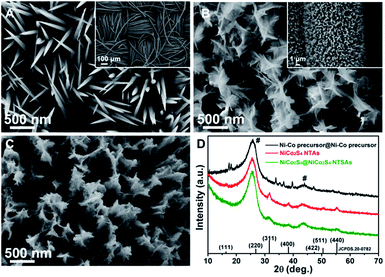
The morphological information of the as-prepared samples was investigated by SEM. As shown in Fig. 2A and inset, we can see that the fibers of carbon textiles haven been uniformly covered by aligned Ni–Co precursor NWAs with relatively smooth surface and sharp tips, which possess a diameter of 50–100 nm in the main region and length up to 2 μm. From Fig. 2B and inset, it is clearly visible that the Ni–Co precursor NWAs have been fully decorated with a few layers of interconnected Ni–Co precursor nanosheets upon a secondary hydrothermal reaction. The abundant empty space among the neighboring nanowires are largely occupied by the shell materials, and the formed hierarchical nanostructures exhibit an apparently increased lateral size of ca. 300 nm with respect to that of pristine Ni–Co precursor nanowires. After the one-step sulfuration process, the NiCo2S4@NiCo2S4 hybrid NTSAs have been successfully fabricated with generally retained array structure, as depicted in Fig. 2C, and the surface of the product has become more rough with numerous mesopores. It is worth noting that we are able to control the growth of NiCo2S4@NiCo2S4 NTSAs on carbon cloth with tunable loading amounts and electrochemical properties (Fig. S1†) by modulating the reaction time for the growth of Ni–Co precursor shells. In order to give the best electrochemical performance, in this work we will mainly focus on the optimized electrode of NiCo2S4@NiCo2S4 NTSAs with shell growth time of 2 h as an illustrative example.
Regarding the crystalline structure and phase purity of the samples, the XRD patterns of NiCo2S4@NiCo2S4 NTSAs, Ni–Co precursor@Ni–Co precursor NWSAs and NiCo2S4 NTAs are presented in Fig. 2D for comparison. The appearance of two dominant diffraction peaks locating at about 26° and 43° are actually arising from the carbon cloth substrate, as marked by “#”.39 For the NiCo2S4@NiCo2S4 hybrid NTSAs, the XRD pattern is almost the same as that of NiCo2S4 NTAs and the broaden peaks centered at 31.5°, 38.2°, 50.3° and 55.1° are readily assigned to the (311), (400), (511) and (440) planes of the cubic NiCo2S4 phase (JCPDS no. 20-0782).22 Notably, it is found that the strong signals from the Ni–Co precursor@Ni–Co precursor NWSAs cannot be detected in the final product of NiCo2S4@NiCo2S4 NTSAs, suggesting the complete conversion of the core/shell structured precursors into their corresponding sulfide counterparts through such a simple one-step anion exchange reaction process.
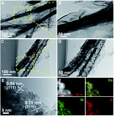
Further insights into the morphology and structure of the products are revealed by TEM and HRTEM. Fig. 3A and B show the representative TEM images of Ni–Co precursor@Ni–Co precursor NWSAs with different magnifications. It is clearly observed that ultrathin Ni–Co precursor nanosheets with wrinkled features are intimately anchored on the surface of Ni–Co precursor nanowires and the core/shell structure with distinct contrasts can be easily distinguished from Fig. 3A and B. As expected, the interior components of Ni–Co precursor nanowires can be continuously etched out owing to the Kirkendall effect during the sulfuration treatment.40,41 Consequently, the solid backbones are gradually converted into hollow tubular structure of NiCo2S4 with an average wall thickness of ca. 15 nm, while the thin shells simply preserve the sheet-like morphology, leading to the formation of hierarchical NiCo2S4@NiCo2S4 hybrid NTSAs, as evidenced by Fig. 3C and D. More detailed TEM observation indicates that the hybrid nanostructures are indeed composed of many crystalline particles (10–20 nm in size) with a large number of interpenetrating mesopores (5–10 nm in size). Such unique core/shell hybrid NTSAs with rich porosity and tubular structure are able to greatly improve the utilization of electroactive materials especially the interior parts, which are highly beneficial for the rapid diffusion of electrolyte ions through these accessible channels during the reversible redox reactions. HRTEM studies of the shell materials (Fig. 3E) reveal two sets of clear lattice fringes with an interplanar spacing of 0.28 nm and 0.54 nm, corresponding well to the (311) and (111) planes of NiCo2S4 phase, respectively.42 The EDS elemental mapping of individual NiCo2S4@NiCo2S4 hybrid NTSAs under HAADF-STEM mode (Fig. 3F) demonstrates that the constituent elements of Ni, Co and S are nearly homogeneously distributed over the entire core/shell nanostructure. The atomic ratio of Ni![[thin space (1/6-em)]](https://www.rsc.org/images/entities/char_2009.gif) :
:![[thin space (1/6-em)]](https://www.rsc.org/images/entities/char_2009.gif) Co
Co![[thin space (1/6-em)]](https://www.rsc.org/images/entities/char_2009.gif) :
:![[thin space (1/6-em)]](https://www.rsc.org/images/entities/char_2009.gif) S is determined to be about 1
S is determined to be about 1![[thin space (1/6-em)]](https://www.rsc.org/images/entities/char_2009.gif) :
:![[thin space (1/6-em)]](https://www.rsc.org/images/entities/char_2009.gif) 2.3
2.3![[thin space (1/6-em)]](https://www.rsc.org/images/entities/char_2009.gif) :
:![[thin space (1/6-em)]](https://www.rsc.org/images/entities/char_2009.gif) 3.7, which is quite approaching the nominal stoichiometric ratio of 1
3.7, which is quite approaching the nominal stoichiometric ratio of 1![[thin space (1/6-em)]](https://www.rsc.org/images/entities/char_2009.gif) :
:![[thin space (1/6-em)]](https://www.rsc.org/images/entities/char_2009.gif) 2
2![[thin space (1/6-em)]](https://www.rsc.org/images/entities/char_2009.gif) :
:![[thin space (1/6-em)]](https://www.rsc.org/images/entities/char_2009.gif) 4 for NiCo2S4 phase. In addition, the O signal can be seldom detected from the main region by EDS spectra (Fig. S2†), further verifying the complete transition of the core/shell structured precursors into targeted sulfides.
4 for NiCo2S4 phase. In addition, the O signal can be seldom detected from the main region by EDS spectra (Fig. S2†), further verifying the complete transition of the core/shell structured precursors into targeted sulfides.
The surface elemental composition and oxidation states of the NiCo2S4@NiCo2S4 NTSAs were analyzed by XPS with results shown in Fig. 4. Fig. 4A exhibits the XPS survey spectrum of the as-prepared sample, indicating the presence of Ni, Co, S, O and C elements on the surface. The emergence of C and O signals are mainly ascribed to the contaminant and surface oxidation of sulfide due to exposure to air, respectively.6,43 Fig. 4B shows the core-level spectrum of Ni 2p as fitted by the Gaussian method, which consists of two spin–orbit doublets and two shake-up satellites. Specifically, the fitting peaks at 855.2 eV and 872.9 eV are indexed to Ni2+, while the peaks at 856.3 eV and 874.2 eV are assigned to Ni3+, along with their satellite peaks at 861.8 eV and 879.7 eV.44 In the case of Co 2p spectrum (Fig. 4C), the multiple peaks at 778.6, 793.6, 781.6 and 797.7 eV belong to Co3+ 2p3/2, Co3+ 2p1/2, Co2+ 2p3/2 and Co2+ 2p1/2, respectively, while the shake-up satellite peaks of Co 2p are observed at 787.0 and 803.1 eV.45 For the S 2p spectrum as shown in Fig. 4D, the deconvoluted peaks at 161.2 eV and 162.4 eV are associated with the S 2p3/2 and S 2p1/2, respectively, while the broad peak at 168.4 eV is mainly attributed to the SOx because of the oxidized S species on the surface of the hybrid nanostructures.43,46 The above XPS results demonstrate the presence of mixed valence states of both metal ions (Co2+/Co3+, and Ni2+/Ni3+) in the NiCo2S4@NiCo2S4 hybrid NTSAs, which can provide rich redox chemistry of the product during the reversible electrochemical reaction process.
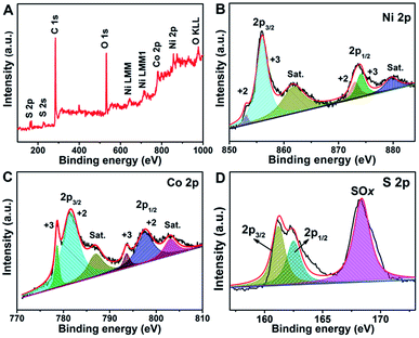 | ||
| Fig. 4 XPS spectra of (A) survey, (B) Ni 2p, (C) Co 2p and (D) S 2p for the NiCo2S4@NiCo2S4 hybrid NTSAs. | ||
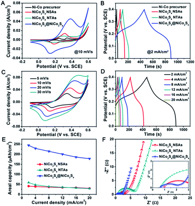
The superior electrochemical properties of the NiCo2S4@NiCo2S4 hybrid NTSAs were first evaluated in a three-electrode configuration with 3 M KOH aqueous solution as the electrolyte. Fig. 5A depicts the typical CV curve of the NiCo2S4@NiCo2S4 hybrid electrode recorded at a scan rate of 10 mV s−1. The electrodes of pristine NiCo2S4 NTAs, NiCo2S4 NSAs, and Ni–Co precursor NWAs were also tested for comparison. Apparently, a pair of distinct redox peaks can be easily observed from each CV profile, which is mainly attributed to the reversible reactions of Ni2+/Ni3+ and Co2+/Co3+/Co4+ redox couples associated with electrolyte OH− ions based on the following equations: NiCo2S4 + OH− + H2O ↔ NiSOH + 2CoSOH + 2e−, CoSOH + OH− ↔ CoSO + H2O + e−.47,48 Moreover, the CV shapes of these electrodes undoubtedly indicate their faradaic characteristics of battery-type electrodes,49 which are quite different from those of typical EDLC-type (such as carbon nanotube, graphene)50 and pseudocapacitive electrodes (such as MnO2, RuO2)51 with nearly rectangular shapes. Besides, the enclosed CV area and peak current density of the NiCo2S4@NiCo2S4 hybrid NTSAs are much larger than that of other electrodes, revealing the much higher electrochemical activity and capacity of the hybrid electrode.52 This conclusion can be verified by the GCD curves, as shown in Fig. 5B, in which the NiCo2S4@NiCo2S4 hybrid electrode shows much longer discharge time. Meanwhile, the obvious nonlinear potential plateaus during the charge–discharge process further confirm their battery-type features. It is worth noting that the contribution of carbon cloth to the total capacity of hybrid electrode can be nearly neglected, as supported by the CV curve in Fig. S3.† Fig. 5C displays a series of CV curves for the NiCo2S4@NiCo2S4 hybrid electrode achieved within a potential window of −0.1 to 0.6 V. With scan rate increased from 5 to 30 mV s−1, the recorded CV curves remain a very similar shape, while the anodic and cathodic peaks shift towards a more positive and negative direction, respectively, implying that the NiCo2S4@NiCo2S4 hybrid electrode is favorable for high-rate energy storage process with good reversibility.53,54 Reflecting from these CV curves, we can also infer that the peak current at various scan rates displays almost a linear relationship with the square root of scan rate, as illustrated in Fig. S4.† Besides, Fig. S5† clearly indicates the contribution of capacitive and diffusion-controlled processes to the total capacity of NiCo2S4@NiCo2S4 electrode, manifesting the diffusion-controlled battery-type behaviors for the hybrid electrode.55,56 Fig. 5D presents the GCD curves for the NiCo2S4@NiCo2S4 hybrid electrode at various current densities ranging from 2 to 20 mA cm−2. The areal and specific capacities can be estimated from the discharge curves, and the corresponding results are plotted as a function of applied current density as shown in Fig. 5E and S6,† respectively, with data of single NiCo2S4 NTAs and NiCo2S4 NSAs also included for comparison. Notably, within the whole current density range, the NiCo2S4@NiCo2S4 hybrid electrode delivers a much higher areal capacity and specific capacity as compared with that of other two electrodes. At a current density of 2 mA cm−2, the NiCo2S4@NiCo2S4 hybrid electrode yields an areal capacity as high as 245 μA h cm−2 (196 mA h g−1 in specific capacity), which is about 4 times that of NiCo2S4 NTAs (59 μA h cm−2) and 6 times that of NiCo2S4 NSAs (41 μA h cm−2), respectively. The much enhanced electrochemical capacity of hybrid electrode can be ascribed to the obvious synergistic effects arising from the unique core–shell structure and components. This result is also superior to those of many previously reported hybrid electrodes on flexible substrates, such as CoNi2Se4@CoFe2Se4,43 CoS2@MoS2,57 Co9S8@Ni(OH)2,58 and CoNi2S4@NiSe.59 When the current density is increased up to an elevated value of 20 mA cm−2, the NiCo2S4@NiCo2S4 hybrid electrode is still able to retain a high areal capacity of 178 μA h cm−2, indicating a good rate capability of 73% retention for the hybrid electrode.
To further understand the substantial improvement of electrochemical performance for the NiCo2S4@NiCo2S4 hybrid electrode, electrochemical impedance spectroscopy (EIS) measurements were carried out in a frequency range of 0.01 Hz to 100 kHz. Fig. 5F compares the corresponding Nyquist plots of EIS spectra for the electrodes of NiCo2S4 NTAs, NiCo2S4 NSAs and NiCo2S4@NiCo2S4 NTSAs. The EIS curves are typically comprised of a semicircle in the high-frequency region which indicates the charge-transfer resistance at the electrode/electrolyte interface, and a sloped straight line in the low-frequency region which reflects the Warburg resistance resulting from the ion diffusion of electrolyte into the electrode pores.60 From Fig. 5F, we can see that the NiCo2S4@NiCo2S4 hybrid electrode displays much lower charge-transfer resistance as compared with that of other electrodes, since the interconnected networks of NiCo2S4@NiCo2S4 hybrid nanostructures are capable of providing more convenient and superb highways for the electron transport within the integrated system. Besides, the slope of straight line for the NiCo2S4@NiCo2S4 hybrid electrode is almost comparable to that of single NiCo2S4 NTAs and NiCo2S4 NSAs, suggesting that the entire core/shell nanostructures are highly accessible for the electrolyte ions penetration and diffusion into the host matrix. Therefore, the favorable fast electron transport and ion diffusion kinetics derived from high electrical conductivity pathways as well as rich porosity and tubular structure are considered to be responsible for the excellent electrochemical properties of the hybrid electrode, especially in terms of high capacity and good rate capability.
Fig. 6 presents the cycling stability of the electrodes from NiCo2S4 NTAs, NiCo2S4 NSAs and NiCo2S4@NiCo2S4 NTSAs tested at a high current density of 10 mA cm−2 over 3000 cycles. For single NiCo2S4 NTAs and NiCo2S4 NSAs, the areal capacities of both electrodes remain nearly constant at a relatively low value of about 40 μA h cm−2 during the whole cycling process. In the case of NiCo2S4@NiCo2S4 hybrid electrode, the areal capacity increases in the first 100 cycles to a maximum value of 216 μA h cm−2 due to the activation of the hybrid electrode materials and then gradually decays with extended cycling. After 3000 cycles, the NiCo2S4@NiCo2S4 hybrid electrode can still manifest a high areal capacity of 172 μA h cm−2 with 86% retention of its initial value as well as nearly 100% Coulombic efficiency (Fig. S7†), indicating the excellent cycling stability of the hybrid electrode.
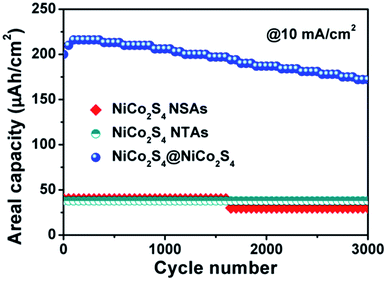 | ||
| Fig. 6 Cycling stability for the electrodes of NiCo2S4 NTAs, NiCo2S4 NSAs and NiCo2S4@NiCo2S4 NTSAs at a current density of 10 mA cm−2. | ||
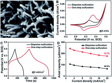
To highlight the merits of the aforementioned NiCo2S4@NiCo2S4 hybrid NTSAs as electrodes applied in supercapacitors, we further conducted comparative studies on NiCo2S4@NiCo2S4 hybrid NTSAs obtained from two different synthetic pathways, namely, one-step sulfuration and stepwise sulfuration processes. Fig. 7A shows the typical SEM image of NiCo2S4@NiCo2S4 hybrid NTSAs supported on carbon cloth synthesized by a stepwise sulfuration process, which involves the growth of Ni–Co precursor nanosheets on the surface of NiCo2S4 NTAs and subsequent transition to NiCo2S4@NiCo2S4 through anion exchange reaction with S2− ions. We find that under similar reaction conditions, the mass loading of NiCo2S4@NiCo2S4 NTSAs on carbon cloth obtained from this method has been obviously decreased to a low amount (0.7 mg cm−2), much less than that of NiCo2S4@NiCo2S4 from the one-step sulfuration process (1.2 mg cm−2). It is proposed that it seems much easier for the Ni–Co precursor nanosheets to grow on the surface of Ni–Co precursor NWAs rather than on that of Ni–Co sulfide, possibly due to their more similar structure and composition of the core/shell materials. More importantly, the NiCo2S4@NiCo2S4 hybrid NTSAs obtained from the one-step sulfuration process exhibit greatly enhanced electrochemical properties with much higher energy storage capacity and better rate capability, as shown in Fig. 7B–D. EIS analyses (Fig. S8†) reveal that the NiCo2S4@NiCo2S4 hybrid NTSAs from the one-step sulfuration process possess a minimized charge-transfer resistance and a much smaller diffusion resistance as indicated by the more ideal straight line in the low frequency region. On the basis of the above results, we can conclude that the one-step sulfuration strategy provides a suitable and alternative synthetic route for the facile fabrication of core/shell structured metal sulfide materials with outstanding electrochemical properties.
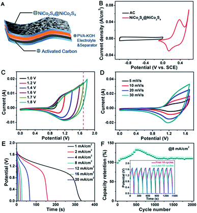
Based on the remarkable electrochemical properties of the NiCo2S4@NiCo2S4 hybrid NTSAs achieved in three-electrode system with good flexibility and conductivity, flexible solid-state HSC devices were fabricated to further evaluate their practical applications. The HSC devices are assembled by employing the optimized NiCo2S4@NiCo2S4 NTSAs as the positive electrode and AC as the negative electrode, as shown in Fig. 8A. Prior to the assembling of full-cell device, the mass ratio of active materials on positive to negative electrode was calculated and controlled to be 1![[thin space (1/6-em)]](https://www.rsc.org/images/entities/char_2009.gif) :
:![[thin space (1/6-em)]](https://www.rsc.org/images/entities/char_2009.gif) 4 based on the charge balance mechanism. Fig. 8B shows the individual CV curves of positive and negative electrodes measured in a three-electrode system at a scan rate of 10 mV s−1, which displays a potential window ranging from −0.1 to 0.6 V, and −1 to 0 V, respectively. Therefore, we can judge that the full-cell device is able to afford a stable voltage of 1.7 V without obvious polarization. With further extending of the voltage to 1.8 V, the appearance of gas bubbling occurs on the electrode due to the decomposition of electrolyte with sudden increment of current density,61 as evidenced by the CV curves with different potential windows in Fig. 8C. Fig. 8D shows the CV curves of the device recorded at various scan rates from 5 to 30 mV s−1 in an electrochemical window of 0 to 1.7 V. The unique tortuous CV profiles are clearly indicative of combined contributions from battery-type and EDLC electrodes to the total capacity. Fig. 8E displays the discharge curves of the device at different current densities. The areal capacity of this device is calculated to be 93.4, 90.4, 75.5, 63.5, 58.4, 51.1 and 45 μA h cm−2, respectively, indicating a retention of 48% with 20-fold increment of the current density. The cycling stability is a critical parameter to determine the practical applications of the HSC devices. Fig. 8F presents the cycling performance of the solid-state HSC device tested at a current density of 8 mA cm−2, showing that the device retains 110% of its initial capacity over 2000 cycles. Moreover, the GCD curves of the first and last 10 cycles are almost overlapped with each other (inset of Fig. 8F), further demonstrating the excellent cycling stability of the solid-state HSC device.
4 based on the charge balance mechanism. Fig. 8B shows the individual CV curves of positive and negative electrodes measured in a three-electrode system at a scan rate of 10 mV s−1, which displays a potential window ranging from −0.1 to 0.6 V, and −1 to 0 V, respectively. Therefore, we can judge that the full-cell device is able to afford a stable voltage of 1.7 V without obvious polarization. With further extending of the voltage to 1.8 V, the appearance of gas bubbling occurs on the electrode due to the decomposition of electrolyte with sudden increment of current density,61 as evidenced by the CV curves with different potential windows in Fig. 8C. Fig. 8D shows the CV curves of the device recorded at various scan rates from 5 to 30 mV s−1 in an electrochemical window of 0 to 1.7 V. The unique tortuous CV profiles are clearly indicative of combined contributions from battery-type and EDLC electrodes to the total capacity. Fig. 8E displays the discharge curves of the device at different current densities. The areal capacity of this device is calculated to be 93.4, 90.4, 75.5, 63.5, 58.4, 51.1 and 45 μA h cm−2, respectively, indicating a retention of 48% with 20-fold increment of the current density. The cycling stability is a critical parameter to determine the practical applications of the HSC devices. Fig. 8F presents the cycling performance of the solid-state HSC device tested at a current density of 8 mA cm−2, showing that the device retains 110% of its initial capacity over 2000 cycles. Moreover, the GCD curves of the first and last 10 cycles are almost overlapped with each other (inset of Fig. 8F), further demonstrating the excellent cycling stability of the solid-state HSC device.
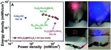
Volumetric energy and power densities are two key parameters to evaluate the performance of flexible electrochemical energy-storage devices. Fig. 9A displays the Ragone plot of the NiCo2S4@NiCo2S4//AC flexible solid-state HSC device, describing the relationship between the volumetric energy density and the volumetric power density. Impressively, the NiCo2S4@NiCo2S4//AC HSC device exhibits a maximum volumetric energy density of 1.03 mW h cm−3 at a power density of 11.4 mW cm−3, and still retains 0.49 mW h cm−3 at a maximum power density of 293 mW cm−3, which are comparable or even superior to many previously reported flexible solid-state HSC devices based on carbon cloth substrates, such as Co9S8//Co3O4@RuO2 (1.21 mW h cm−3 at 13.29 mW cm−3),62 Ni0.34Co0.66Se2//AC (0.47 mW h cm−3 at 37.5 mW cm−3),63 CoSe2//AC (0.59 mW h cm−3 at 0.28 mW cm−3),64 and Fe2O3@PPy//MnO2 (0.22 mW h cm−3 at 165.5 mW cm−3).65 For the sake of comparison, the gravimetric energy and power densities of the HSC device are also provided in the ESI (Fig. S9†), which shows a maximum energy density of 19 W h kg−1 at 206 W kg−1. To demonstrate the practical applications of our HSC devices, two flexible solid-state devices are assembled and connected in series. After charging in a short time, the devices can easily power 12 red or blue LEDs brightly for several minutes. Owing to the flexible feature of the hybrid electrode, the CV curves of the device are nearly overlapped with each other even after 100 times of folding as shown in Fig. S10,† indicating the excellent mechanical stability for our flexible energy storage device. Our work demonstrates the great potential of the NiCo2S4@NiCo2S4 hybrid NTSAs as superior electrodes for high-performance flexible energy storage devices.
Conclusions
In summary, we have successfully fabricated 3D hierarchical NiCo2S4@NiCo2S4 core/shell hybrid NTSAs on flexible carbon cloth via a simple and versatile one-step sulfuration strategy. The as-prepared NiCo2S4@NiCo2S4 hybrid NTSAs have favorable kinetics of electron transport and ion diffusion in the integrated system, due to their tubular structure, high electrical conductivity and rich porosity. Taking advantages of these unique features, the optimized NiCo2S4@NiCo2S4 hybrid electrode yields an enhanced areal capacity of 245 μA h cm−2 at 2 mA cm−2 with good rate capability (73% from 2 to 20 mA cm−2) and cycling stability (86% at 10 mA cm−2 over 3000 cycles). Moreover, the assembled flexible solid-state HSC devices based on NiCo2S4@NiCo2S4 hybrid NTSAs exhibit a maximum volumetric energy density of 1.03 mW h cm−3 at a power density of 11.4 mW cm−3 with excellent cycling stability. Our work demonstrates the possibility of designing and fabricating core/shell structured metal sulfides through a facile one-step sulfuration process, and as well as the great potential of these materials as advanced electrodes for high-performance HSC devices.Conflicts of interest
There are no conflicts to declare.Acknowledgements
The authors gratefully acknowledge the financial support from Zhejiang Provincial Natural Science Foundation of China (No. LY18E020011), National Natural Science Foundation of China (No. 51402262), the 521 Talent Project of Zhejiang Sci-Tech University. We also thank Dr Liqiang Zhang (State Key Laboratory of Heavy Oil Processing, China University of Petroleum) for great assistance with the TEM techniques.Notes and references
- B. Dunn, H. Kamath and J.-M. Tarascon, Science, 2011, 334, 928–935 CrossRef CAS PubMed.
- Y.-G. Guo, J.-S. Hu and L.-J. Wan, Adv. Mater., 2008, 20, 2878–2887 CrossRef CAS.
- Z. Yang, J. Zhang, M. C. W. Kintner-Meyer, X. Lu, D. Choi, J. P. Lemmon and J. Liu, Chem. Rev., 2011, 111, 3577–3613 CrossRef CAS PubMed.
- G. Liu, B. Wang, T. Liu, L. Wang, H. Luo, T. Gao, F. Wang, A. Liu and D. Wang, J. Mater. Chem. A, 2018, 6, 1822–1831 RSC.
- W. Chen, C. Xia and H. N. Alshareef, ACS Nano, 2014, 8, 9531–9541 CrossRef CAS PubMed.
- G. Nagaraju, S. M. Cha, S. C. Sekhar and J. S. Yu, Adv. Energy Mater., 2017, 7, 1601362 CrossRef.
- D. P. Dubal, O. Ayyad, V. Ruiz and P. Gomez-Romero, Chem. Soc. Rev., 2015, 44, 1777–1790 RSC.
- Y. Yang, D. Cheng, S. Chen, Y. Guan and J. Xiong, Electrochim. Acta, 2016, 193, 116–127 CrossRef CAS.
- W. Zuo, R. Li, C. Zhou, Y. Li, J. Xia and J. Liu, Adv. Sci., 2017, 4, 1600539 CrossRef PubMed.
- X. Xia, D. Chao, Z. Fan, C. Guan, X. Cao, H. Zhang and H. J. Fan, Nano Lett., 2014, 14, 1651–1658 CrossRef CAS PubMed.
- Y. F. Yuan, X. H. Xia, J. B. Wu, X. H. Huang, Y. B. Pei, J. L. Yang and S. Y. Guo, Electrochem. Commun., 2011, 13, 1123–1126 CrossRef CAS.
- X. Liu, S. Shi, Q. Xiong, L. Li, Y. Zhang, H. Tang, C. Gu, X. Wang and J. Tu, ACS Appl. Mater. Interfaces, 2013, 5, 8790–8795 CrossRef CAS PubMed.
- Z. Zhan, S. Chen, J. Xie, Y. Yang and J. Xiong, J. Alloys Compd., 2017, 722, 928–937 CrossRef CAS.
- Y. Zhang, H. Liu, M. Huang, J. M. Zhang, W. Zhang, F. Dong and Y. X. Zhang, ChemElectroChem, 2017, 4, 721–727 CrossRef CAS.
- M. Huang, Y. Zhang, F. Li, L. Zhang, Z. Wen and Q. Liu, J. Power Sources, 2014, 252, 98–106 CrossRef CAS.
- G. Zhang and X. W. Lou, Adv. Mater., 2013, 25, 976–979 CrossRef CAS PubMed.
- Y. Wang, D. Zhou, D. Zhao, M. Hou, C. Wang and Y. Xia, J. Electrochem. Soc., 2013, 160, A98–A104 CrossRef CAS.
- J. Chen, X. Wang, J. Wang and P. S. Lee, Adv. Energy Mater., 2016, 6, 1501745 CrossRef.
- H. Chen, L. Hu, M. Chen, Y. Yan and L. Wu, Adv. Funct. Mater., 2014, 24, 934–942 CrossRef CAS.
- M. Li, P. Yuan, S. Guo, F. Liu and J. P. Cheng, Int. J. Hydrogen Energy, 2017, 42, 28797–28806 CrossRef CAS.
- R. Zou, M. F. Yuen, L. Yu, J. Hu, C.-S. Lee and W. Zhang, Sci. Rep., 2016, 6, 20264 CrossRef CAS PubMed.
- H. Chen, J. Jiang, L. Zhang, D. Xia, Y. Zhao, D. Guo, T. Qi and H. Wan, J. Power Sources, 2014, 254, 249–257 CrossRef CAS.
- J. Yang, M. Ma, C. Sun, Y. Zhang, W. Huang and X. Dong, J. Mater. Chem. A, 2015, 3, 1258–1264 RSC.
- H. Wan, J. Liu, Y. Ruan, L. Lv, L. Peng, X. Ji, L. Miao and J. Jiang, ACS Appl. Mater. Interfaces, 2015, 7, 15840–15847 CrossRef CAS PubMed.
- Y. Zhang, X. Wang, M. Shen, X. Fu, M. Huang, X. Liu and Y. X. Zhang, J. Mater. Sci., 2019, 54, 4821–4830 CrossRef CAS.
- Y. M. Chen, Z. Li and X. W. Lou, Angew. Chem., Int. Ed., 2015, 54, 10521–10524 CrossRef CAS PubMed.
- Z. Zhang, X. Huang, H. Wang, S. H. Teo and T. Ma, J. Alloys Compd., 2019, 771, 274–280 CrossRef CAS.
- L. Shen, L. Yu, H. B. Wu, X.-Y. Yu, X. Zhang and X. W. Lou, Nat. Commun., 2015, 6, 6694 CrossRef CAS PubMed.
- J. Liao, P. Zou, S. Su, A. Nairan, Y. Wang, D. Wu, C.-P. Wong, F. Kang and C. Yang, J. Mater. Chem. A, 2018, 6, 15284–15293 RSC.
- S. Cheng, T. Shi, Y. Huang, X. Tao, J. Li, C. Cheng, G. Liao and Z. Tang, Ceram. Int., 2017, 43, 2155–2164 CrossRef CAS.
- W. Li, B. Zhang, R. Lin, S. Ho-Kimura, G. He, X. Zhou, J. Hu and I. P. Parkin, Adv. Funct. Mater., 2018, 28, 1705937 CrossRef.
- X.-F. Lu, A.-L. Wang, H. Xu, X.-J. He, Y.-X. Tong and G.-R. Li, J. Mater. Chem. A, 2015, 3, 16560–16566 RSC.
- X. Wang, Q. Zhang, J. Sun, Z. Zhou, Q. Li, B. He, J. Zhao, W. Lu, C.-p. Wong and Y. Yao, J. Mater. Chem. A, 2018, 6, 8030–8038 RSC.
- J. Xiao, L. Wan, S. Yang, F. Xiao and S. Wang, Nano Lett., 2014, 14, 831–838 CrossRef CAS PubMed.
- W. Fu, C. Zhao, W. Han, Y. Liu, H. Zhao, Y. Ma and E. Xie, J. Mater. Chem. A, 2015, 3, 10492–10497 RSC.
- C. Zhang, M. Hou, X. Cai, J. Lin, X. Liu, R. Wang, L. Zhou, J. Gao, B. Li and L. Lai, J. Mater. Chem. A, 2018, 6, 15630–15639 RSC.
- M. Liang, M. Zhao, H. Wang, J. Shen and X. Song, J. Mater. Chem. A, 2018, 6, 2482–2493 RSC.
- D. Cheng, Y. Yang, J. Xie, C. Fang, G. Zhang and J. Xiong, J. Mater. Chem. A, 2015, 3, 14348–14357 RSC.
- Y. Mo, Q. Ru, J. Chen, X. Song, L. Guo, S. Hu and S. Peng, J. Mater. Chem. A, 2015, 3, 19765–19773 RSC.
- D. Cai, D. Wang, C. Wang, B. Liu, L. Wang, Y. Liu, Q. Li and T. Wang, Electrochim. Acta, 2015, 151, 35–41 CrossRef CAS.
- J. Pu, T. Wang, H. Wang, Y. Tong, C. Lu, W. Kong and Z. Wang, ChemPlusChem, 2014, 79, 577–583 CrossRef CAS.
- T. Wang, Q. Le, G. Zhang, S. Zhu, B. Guan, J. Zhang, S. Xing and Y. Zhang, Electrochim. Acta, 2016, 211, 627–635 CrossRef CAS.
- A. R. CVVM Gopi and H. J. Kim, J. Mater. Chem. A, 2018, 6, 7439–7448 RSC.
- D. Kong, W. Ren, C. Cheng, Y. Wang, Z. Huang and H. Y. Yang, ACS Appl. Mater. Interfaces, 2015, 7, 21334–21346 CrossRef CAS PubMed.
- L. Shen, J. Wang, G. Xu, H. Li, H. Dou and X. Zhang, Adv. Energy Mater., 2015, 5, 1400977 CrossRef.
- Y. Li, Y. Zhou, H. Wen, J. Yang, C. Maouche, Q. Liu, Y. Wu, C. Cheng, J. Zhu and X. Cheng, Dalton Trans., 2018, 47, 14992–15001 RSC.
- L. Huang, D. Chen, Y. Ding, S. Feng, Z. L. Wang and M. Liu, Nano Lett., 2013, 13, 3135–3139 CrossRef CAS PubMed.
- M. Yan, Y. Yao, J. Wen, L. Long, M. Kong, G. Zhang, X. Liao, G. Yin and Z. Huang, ACS Appl. Mater. Interfaces, 2016, 8, 24525–24535 CrossRef CAS PubMed.
- B. Y. Guan, L. Yu, X. Wang, S. Song and X. W. Lou, Adv. Mater., 2017, 29, 1605051 CrossRef PubMed.
- L. L. Zhang and X. S. Zhao, Chem. Soc. Rev., 2009, 38, 2520–2531 RSC.
- T. Brousse, D. Belanger and J. W. Long, J. Electrochem. Soc., 2015, 162, A5185–A5189 CrossRef CAS.
- D. Cai, D. Wang, B. Liu, L. Wang, Y. Liu, H. Li, Y. Wang, Q. Li and T. Wang, ACS Appl. Mater. Interfaces, 2014, 6, 5050–5055 CrossRef CAS PubMed.
- D. Kong, C. Cheng, Y. Wang, J. I. Wong, Y. Yang and H. Y. Yang, J. Mater. Chem. A, 2015, 3, 16150–16161 RSC.
- W. Zeng, G. Zhang, X. Wu, K. Zhang, H. Zhang, S. Hou, C. Li, T. Wang and H. Duan, J. Mater. Chem. A, 2015, 3, 24033–24040 RSC.
- V. Augustyn, P. Simon and B. Dunn, Energy Environ. Sci., 2014, 7, 1597–1614 RSC.
- Q. Yang, Y. Liu, L. Xiao, M. Yan, H. Bai, F. Zhu, Y. Lei and W. Shi, Chem. Eng. J., 2018, 354, 716–726 CrossRef CAS.
- C. Su, J. Xiang, F. Wen, L. Song, C. Mu, D. Xu, C. Hao and Z. Liu, Electrochim. Acta, 2016, 212, 941–949 CrossRef CAS.
- F. Zhu, M. Yan, Y. Liu, H. Shen, Y. Lei and W. Shi, J. Mater. Chem. A, 2017, 5, 22782–22789 RSC.
- Z. Tang, C. Jia, Z. Wan, Q. Zhou, X. Ye and Y. Zhu, RSC Adv., 2016, 6, 112307–112316 RSC.
- Z. Gao, W. Yang, J. Wang, N. Song and X. Li, Nano Energy, 2015, 13, 306–317 CrossRef CAS.
- J. Ji, L. L. Zhang, H. Ji, Y. Li, X. Zhao, X. Bai, X. Fan, F. Zhang and R. S. Ruoff, ACS Nano, 2013, 7, 6237–6243 CrossRef CAS PubMed.
- J. Xu, Q. Wang, X. Wang, Q. Xiang, B. Hang, D. Chen and G. Shen, ACS Nano, 2013, 7, 5453–5462 CrossRef CAS PubMed.
- P. Xu, W. Zeng, S. Luo, C. Ling, J. Xiao, A. Zhou, Y. Sun and K. Liao, Electrochim. Acta, 2017, 241, 41–49 CrossRef CAS.
- N. Yu, M.-Q. Zhu and D. Chen, J. Mater. Chem. A, 2015, 3, 7910–7918 RSC.
- L. Wang, H. Yang, X. Liu, R. Zeng, M. Li, Y. Huang and X. Hu, Angew. Chem., Int. Ed., 2017, 56, 1105–1110 CrossRef CAS PubMed.
Footnote |
| † Electronic supplementary information (ESI) available. See DOI: 10.1039/c8ra10435b |
| This journal is © The Royal Society of Chemistry 2019 |


