 Open Access Article
A review of femtosecond laser-structured superhydrophobic or underwater superoleophobic porous surfaces/materials for efficient oil/water separation
Jiale Yong
ab,
Qing Yang
c,
Chunlei Guo
*b,
Feng Chen
 *a and
Xun Hou
a
aState Key Laboratory for Manufacturing System Engineering, Shaanxi Key Laboratory of Photonics Technology for Information, School of Electronics & Information Engineering, Xi'an Jiaotong University, Xi'an, 710049, PR China. E-mail: chenfeng@mail.xjtu.edu.cn
bThe Institute of Optics, University of Rochester, Rochester, New York 14627, USA. E-mail: guo@optics.rochester.edu
cSchool of Mechanical Engineering, Xi'an Jiaotong University, Xi'an, 710049, PR China
First published on 23rd April 2019
Abstract
Oil/water separation (OWS) technology has become an increasingly crucial tool to protect the environment and reduce the economic losses caused by the discharge of oily wastewater and oil spills. Recently, porous materials with superwettability have been applied in effective OWS and have achieved tremendous success. Herein, we review recent advancements of OWS utilizing femtosecond (fs) laser-structured superhydrophobic or underwater superoleophobic porous materials. We will review the enabling materials processing and treatment methods, their surface wettability, the separating methods and processes, and the separation mechanisms. Inspired by lotus leaves and fish scales, superhydrophobic and underwater superoleophobic properties are artificially achieved on substrate surfaces by fs laser processing. By using fs laser-structured superwetting porous materials, various oil/water mixtures (OWMs) are successfully separated through different separation methods. Presently, the research of fs laser-based OWS is still in its infancy. We will also discuss the current challenges and future prospects in this emerging field. It is expected that the advanced features of fs laser microfabrication will lead to exciting applications for OWS.
1. Introduction
Oil/water separation (OWS, i.e., the separation of oil and water) has become an urgent issue and a worldwide challenge because of the ever increasing frequency and amount of oily wastewater discharge and oil spill accidents.1–6 The oil pollution not only seriously destroys the ecological environment but also causes huge economic loss.5–9 A typical example is the Gulf of Mexico oil spill, which happened in 2010 and caused about 2 × 10⁸ gallons of crude oil to be leaked on the sea surface (Fig. 1a and b).5,10 Such an unprecedented environmental catastrophe has resulted in immeasurable damage to the marine ecosystem as well as public health (Fig. 1c and d). To protect the environment and reduce economic loss, there is an urgent need for developing advanced materials and technologies for effective OWS. Conventional materials and methods (e.g., absorption, gravity separation, flotation, skimming, and centrifugation) used to solve those oil-pollution problems often suffer from many limitations, such as low separation efficiency, high cost, low selectivity, the need of driving energy, and the generation of secondary pollutants.1,3 Recently, porous materials with opposite superwettabilities to water and oil are successfully applied in the field of OWS.11–33 Those materials usually have both superhydrophobicity and superoleophilicity, or have both superoleophobicity and superhydrophilicity. For instance, Feng et al. firstly fabricated a superhydrophobic film (i.e., rough Teflon-coated metal mesh) that also had superoleophilicity.11 The mesh successfully separated the oil/water mixture (OWM, i.e., the mixture of oil and water). The porous film allowed oil to permeate through but completely intercepted the water phase. Xue et al. prepared an underwater superoleophobic porous film (i.e., nanostructured hydrogel-coated metal mesh) and also achieved OWS by using such a mesh.19 When poured OWM onto the water-wetted mesh, the water phase could wet and penetrate through the mesh because of the superhydrophilicity, while the oil phase always remained above the mesh. Inspired by the above-mentioned research works, a large number of porous materials with superhydrophobicity/superoleophilicity or superoleophobicity/superhydrophilicity have been developed in order to achieve OWS.12,13,16,21,22,24,25,34–46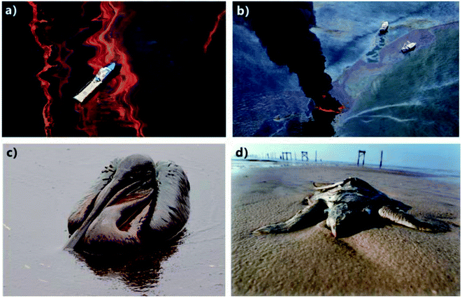 | ||
| Fig. 1 Gulf of Mexico oil spill accident. (a and b) Leaked crude oil covering on the ocean surface. (c and d) Seabirds and sea turtles being killed by the leaked crude oil. Reproduced from ref. 5 with permission from RSC, copyright 2018. | ||
With the advent of a femtosecond (fs) laser, the microfabrication based on the fs laser has been rapidly applied in the field of advanced nano/microfabrication and other modern manufacturing.47–55 Such technology has many definite advantages in designing surface microstructures, including small heat-affected zone, high spatial resolution, non-contact manufacturing, etc.56–59 In particular, fs laser can process almost all of the known materials and directly create micro/nanoscale structures on the surfaces of various kinds of materials (e.g., semiconductors, metals, polymers, glasses, and ceramics) through simple one-step ablation.56–60 In addition, the fs laser can not only generate uniform large-area rough microstructures on the surface of a substrate but also drill microholes array through a thin film.28,47,61,62 In recent years, fs laser microfabrication obtains great success in adjusting the surface wettability of different solid materials, because wettability is mainly depended on the surface microstructure and chemical composition of the material surfaces.47,48,63–72 Various superhydrophobic surfaces and underwater superoleophobic surfaces have been prepared through fs laser processing.47–55,61,73–77 The fs laser-structured superwetting porous materials also have important applications in OWS.16,28,62,78–81
In this paper, we will review the recent advancements of femtosecond laser-induced superhydrophobic or underwater superoleophobic porous materials and their applications in OWS. This review starts with the introduction of the significance and urgency of performing highly efficient OWS (Section 1). Then, the theoretical basis of wettability, the features of fs laser microfabrication, and the typical separating ways based on the superwetting porous materials are presented as the related background (Section 2). The next part shows the practical applications of the fs laser-induced superwetting porous materials towards OWS (Section 3). We will focus on discussing the wettability of the separation materials, the separation method and operation, and the separation mechanisms. In the end, the current challenges in the field of OWS using the fs laser-induced superhydrophobic or superoleophobic porous materials will also be discussed (Section 4).
2. Background
Asians love lotus very much because it grows in the silt but not imbrued (Fig. 2a). Rain droplets or dewdrops can maintain an approximately spherical shape on a lotus leaf. As the lotus leaf is slightly shaken, the droplets will freely roll off and take away the contaminant on the leaf surface, achieving cleaning function by itself. This phenomenon is called “lotus effect” or “self-cleaning effect”.82–84 Such property is ascribed to the superhydrophobicity of the lotus leaf surface (Fig. 2d).84 It has been demonstrated that a large number of papillae with the size of several micrometers randomly distribute on the surface of lotus leaf (Fig. 2b). Every papilla is further covered with abundant nanorods and a hydrophobic wax crystal layer (Fig. 2c). If a water droplet is placed on the lotus leaf, the hydrophobic micro/nanoscale hierarchical structure will lift the droplet and reduce the effective contact area between the surface microstructure and the droplet, forming a layer of trapped air cushion underneath this water droplet.85–89 Such Cassie wetting state results in the strong water-repellent ability of lotus leaf.70,86 The natural synergy between the hierarchical rough microstructure and the low-surface-energy chemical composition endows lotus leaf with excellent superhydrophobicity and ultralow adhesion to water droplet. There also exist many other animals and plants having superhydrophobic surfaces in nature, such as legs of a water strider,90,91 red rose petal,92 rice leaf,93,94 butterfly wing,95 mosquito eye,96 feet of gecko,97 Salvinia plants,89,98 and desert beetle.99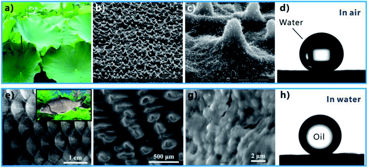 | ||
| Fig. 2 Superhydrophobicity of lotus leaf and underwater superoleophobicity of fish scale. (a) Lotus leaves. (b and c) Surface microstructure of a lotus leaf. (d) Water droplet on the lotus leaf in air. (e) Photography of fish scales. The inset shows a fish in water. (f and g) Surface microstructure of fish scale. (h) Oil droplet on a fish scale in water. (a–d) Reproduced from ref. 84 with permission from ACS, copyright 2017. (e–h) Reproduced from ref. 100 with permission from Wiley, copyright 2009. | ||
It is found that the fish scale (Fig. 2e) has the strong anti-oil capability in water, allowing fish to freely swim in the oil-contaminated water with a clean skin. The underlying mechanism of such underwater oil repellency has been revealed by Jiang's research group, which is considered as the direct result of the superoleophobicity of the fish scales in a water medium.100 There are many oriented micropapillae distributing on the fan-shaped fish scales (Fig. 2f). The micropapillae are 200 ± 100 μm in length and 35 ± 5 μm in width. The surface of the micropapillae is further decorated with abundant fine-scale “nano-pimples” (Fig. 2g). In addition, the fish scales are mainly made up of the skeleton of hydrophilic calcium phosphate and protein, coated with a relatively thin mucus layer. The rough microstructure and the hydrophilic composition result in superhydrophilicity of the fish scales.7,84,100 In the water environment where fishes generally live, the rough microstructures of fish scales are wet by water and water is trapped in such microstructures. As long as an underwater oil droplet comes in contact with the fish scale, this droplet will just touch the tips of the surface microstructure because it is repelled by the trapped water cushion. Therefore, the cooperation of the rough surface morphology and hydrophilic chemistry allows underwater oil droplets on a fish scale to be at the underwater Cassie wetting state, endowing the fish scale with underwater superoleophobicity and great oil repellency (Fig. 2h).49,70,100 Moreover, the shell of a clam,101 the back of a lotus leaf,102 seaweed,103 and filefish skin104 also possess an underwater superoleophobic surface.
Inspired by the above-mentioned creatures, more and more superhydrophobic materials and underwater superoleophobic materials are developed by properly designing surface microstructures and chemical composition on different substrates.47,48,63–70
2.1 Theoretical basis on surface wettability
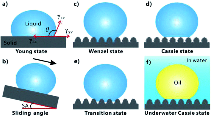
Surface wettability can be evaluated by testing the contact angle (CA) and sliding angle (SA) of a small liquid droplet on the target substrate. The CA is generally used to describe the static aspect of surface wettability while the SA can reflect the dynamic behavior of a droplet on the substrate.70,71,105 For a droplet on a material surface, CA (it appears as “θ” in the formula) refers to the angle between the tangent to the air/liquid curved surface and the liquid/solid interface at the three-phase contact line (TPCL), as shown in Fig. 3a. Water droplet has a water CA (WCA) smaller than 90° on a hydrophilic substrate while a WCA larger than 90° on a hydrophobic substrate. For the extreme cases, WCA ≤ 10° and WCA ≥ 150° are the criterions of superhydrophilicity and superhydrophobicity, respectively. When the substrate is gradually tilted until the droplet is just able to roll away, the tilted angle is known as the SA (Fig. 3b). A smaller SA value means that the substrate shows a smaller adhesion to the liquid droplet.75,106–111 In addition to a very large CA, the lotus leaf and fish scale also have an ultralow adhesion to water and underwater oil droplets with SA less than 10°, respectively.7,82–84,100Young wetting model is generally used to describe the wettability of a droplet on a flat substrate, as shown in Fig. 3a.70,112 The CA (θ) can be estimated by Young's equation:
 | (1) |
In most cases, the substrate surface usually has a different degree of roughness rather than ideal smoothness. The rough surface microstructures also have great influence on the wettability of the materials besides their chemical composition.85 The wettability of a liquid droplet on a rough substrate can be described by three wetting models: Wenzel state, transition state, and Cassie state.69,70,85,105,113 In the Wenzel state, the liquid droplet wets the rough microstructures of the substrate surface so that the valleys of the microstructures are fully filled with liquid (Fig. 3c).114 Wenzel pointed out that the roughness-induced increase of the actual surface area of the rough solid surface is able to amplify the wetting nature of the substrate. Therefore, he carried on a modification to Young's equation as:
 | (2) |
When the valleys of the microstructures repel liquid and the liquid is difficult to penetrate into the valleys, the liquid droplet can just sit on the top of the surface microstructure, with air pockets trapped beneath the droplet (Fig. 3d). Cassie and Baxter put forward a new wetting state to describe a small droplet on a solid/air heterogeneous substrate by the following:115
cos![[thin space (1/6-em)]](https://www.rsc.org/images/entities/char_2009.gif) θ* = f θ* = f![[thin space (1/6-em)]](https://www.rsc.org/images/entities/char_2009.gif) cos cos![[thin space (1/6-em)]](https://www.rsc.org/images/entities/char_2009.gif) θ + f − 1 θ + f − 1
| (3) |
Sometimes, the liquid droplet only partially penetrates into the valley of the surface microstructures (Fig. 3e). Such wetting model is considered at the transition state from the Wenzel to the Cassie states.75,85,106,108,110,111,116–119 The rough surfaces at the Wenzel/Cassie states usually exhibit very high/low adhesion to a droplet, respectively. Interestingly, the surfaces belonging to transition model often have different adhesion ranging from low to high to liquid droplets, which depends on the extent of the liquid penetrating into the surface microstructures.106,108,110,117,118
In the Cassie state, the trapped air layer effectively reduces the contact between the substrate and the droplet, so such substrate has perfect water repellency. The Cassie state can be extended to a solid/water/oil three-phase system. When a rough (super) hydrophilic substrate is immersed in water, the surface microstructure will be completely wetted by water. As shown in Fig. 3f, a trapped water cushion will form between the material surface and the oil droplet after placing an oil droplet onto such pre-wetted substrate. Oil droplet only touches the peak of the surface microstructure, like sitting on such solid–water composite interface. Such oil droplet is at the underwater Cassie state, which was originally proposed to explain the anti-oil ability of fish scale.21,24,100,120–125 The repulsive force between the trapped water layer and oils endows the substrate with the great oil-repellent property.
2.2 Features of femtosecond laser microfabrication
Laser processing is an important tool in modern manufacturing, extreme machining, and ultra-precise machining. Among the laser pulses with different duration/width, fs laser becomes a bright star in advanced nano/microfabrication nowadays due to its ultra-short pulse width as well as extremely high peak intensity.56–59,126 Those features allow the fs laser to have many definite advantages during ablating a solid substrate, including small heat-affected zone around the ablation spot, high spatial resolution, extensive material processing, non-contact manufacturing, etc.56–59 Fs laser can ablate almost all of the known materials and directly generate microscale and nanoscale structures on the material surfaces via simple ablation.56–58,127–151 When the fs laser pulses are irradiated on a solid substrate (e.g., silicon surface), the multiphoton/avalanche ionization will occur because of the nonlinear absorption of the substrate, leading to part of laser energy be absorbed by electrons.60,127,135,152 The energy absorbed by electrons is further forwarded to the crystal lattice and then diffuses into material. Meanwhile, the generated plasma with high pressure and high temperature expands and bursts out of the ablation spot, and the ionized materials on the substrate surface are removed away. The ejection of the ablated material leads to the permanent damage of substrate surface and the formation of various rough surface microstructures. In addition, a large number of ejected molten particles fall down and solidify, known as the re-crystallization process, resulting in abundant self-assembly fine nano-protrusions coating on such microstructures.127 Fig. 4a and b shows the SEM images of a steel foil (thickness of 100 μm) with a microhole structure ablated by nanosecond laser (pulse width of 3.3 ns) and fs laser (pulse width of 200 fs), respectively.153 Regarding the nanosecond laser-treated surface, severe swelling formed around the ablated microhole, resulted from melting (Fig. 4a). On the contrary, the edge of the fs laser-induced microhole was very sharp and its wall was very steep, demonstrating a limited heat-affected zone and high precision during fs laser micromachining (Fig. 4b). The contrast effect can also be verified on the transparent material surfaces. Fig. 4c and d reveals the microstructures of the NaCl surfaces that were ablated by 16 ns and 300 fs lasers (wavelength = 248 nm), respectively.154 NaCl was transparent at the wavelength of 248 nm in this experiment. Taking advantages of limited heat-affected zone and high precision, various very sophisticated microstructures can be designed and fabricated by fs laser microfabrication, as well as a series of special surface wettabilities.47,48,61,73,86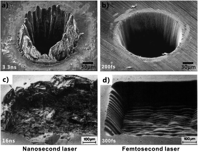 | ||
| Fig. 4 SEM images of the substrates after nanosecond laser and fs laser ablation, respectively. (a and b) Steel foil with thickness of 100 μm: (a) pulse width of 3.3 ns, (b) pulse width of 200 fs. (c and d) Monocrystalline sodium chloride (NaCl) surface: (c) pulse width of 16 ns, (d) pulse width of 300 fs. (a and b) Reproduced from ref. 153 with permission from Springer, copyright 1996. (c and d) Reproduced from ref. 154 with permission from Materials Research Society, copyright 1989. | ||
Fig. 5 shows a laser processing system.86 The sample is mounted on a 3D translation platform whose movement is precisely controlled by a computer. Optical lens (e.g., objective lens or plane-convex lens) is usually used to focus the laser beam onto the sample surface. The energy of the focused laser beam is changed by a variable attenuator. Turning on/off the laser beam is controlled by an electromechanical shutter. In general, there are mainly two processing manners used in laser microfabrication, i.e., the line-by-line (LBL) scanning manner and the point-by-point (PBP) ablation (inset of Fig. 5). The former manner is widely used to generate separated microgrooves or uniform large-area rough surface microstructures, while the latter can drill microholes array. The crucial parameters in the LBL laser scanning include laser energy, scanning speed, and the interval/shift of the scanning lines. By contrast, laser power, the exposure time of every ablation point, and the space between ablated spots are the crucial parameters in the PBP laser ablation. The main parameters that were adopted to fabricate superwetting surfaces introduced in this review are listed in Table 1.
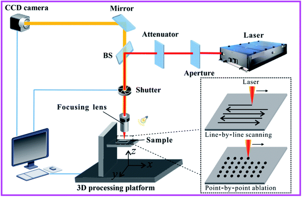 | ||
| Fig. 5 Schematic diagram of a typical laser processing system. The inset shows two main processing manners used in laser microfabrication: LBL scanning manner and PBP ablation. Reproduced from ref. 86 with permission from RSC, copyright 2017. | ||
| Section in this review | Samples | Parameters of laser system | Processing parameters | References | |||||
|---|---|---|---|---|---|---|---|---|---|
| Material | Wettability | Pulse duration/width | Central wavelength | Repetition rate | Laser power | Scanning speed | Interval of scanning lines | ||
| 3.1 | PTFE | Superhydrophobicity, superoleophilicity | 50 fs | 800 nm | 1 kHz | 20 mW | 5 mm s−1 | 5 μm | 16 |
| 3.2 | Aluminum | Underwater superoleophobicity | 104 fs | 800 nm | 1 kHz | 50 mW | PBP ablation | 28 | |
| 3.2 | Titanium | Underwater superoleophobicity | 50 fs | 800 nm | 1 kHz | 3.1–15.5 J cm−2 | PBP ablation | 78 | |
| 3.2 | Stainless steel mesh | Underwater superoleophobicity | 250 fs | 1030 nm | 75 kHz | 7 W | 1 m s−1 | 10 μm | 79 |
| 3.3 | Copper mesh | Superhydrophobicity, underwater superoleophobicity | 580 mW, 100 mW | 2 mm s−1 | 80 | ||||
| 3.4 | Brass mesh | Underoil superhydrophobicity, underwater superoleophobicity | 100 ns | 1064 nm | 20 kHz | 10 W | 500 mm s−1 | 10 μm | 81 |
| 3.5 | Aluminum foil | Superhydrophobicity, underwater superoleophobicity | 104 fs | 800 nm | 1 kHz | 0.6–4 mW | 15 mm s−1 | 20 μm | 62 |
Fs laser has been widely applied in high-precision and high-quality micro/nanomachining, including nano-grating, cutting, drilling, generating micro/nanostructures, and surface patterning and texturing.56–59 Surface wettability of a solid substrate is mainly determined by the surface microstructure and chemical composition of the material surface.70,107,111,112,155–165 The outstanding features of fs laser microfabrication make this technology have great success in designing wettability of solid materials.47–55,61,73–77,152,166–171 Compared to the common methods for achieving superhydrophobicity and underwater superoleophobicity, fs laser microfabrication has some particularly special aspects. Firstly, the fs laser is able to ablate most of the materials, without being restricted to specific materials. Secondly, different micro/nano-structures can be directly built on materials surfaces just by a one-step ablating process, so the fabrication process is rather simple. Thirdly, the laser processing position is precisely controlled by a program; thereby various micropatterns can be easily obtained without the need of expensive masks. Sophisticated and heterogeneous wettability is possible to be exhibited by those micro-patterns. Fourthly, the rough surface morphology, as well as the surface wettability, can be simply adjusted by the used laser power, the scanning speed and track during laser ablation. Finally, laser processing is a physical and mechanical process, without the need of toxic and dangerous chemical reaction and other operation steps. The diversity of the surface wettability of the fs laser-structured materials allows these materials to potentially separate OWM in a variety of ways.16,28,62,78–81
2.3 Oil/water separation by the superwetting porous materials
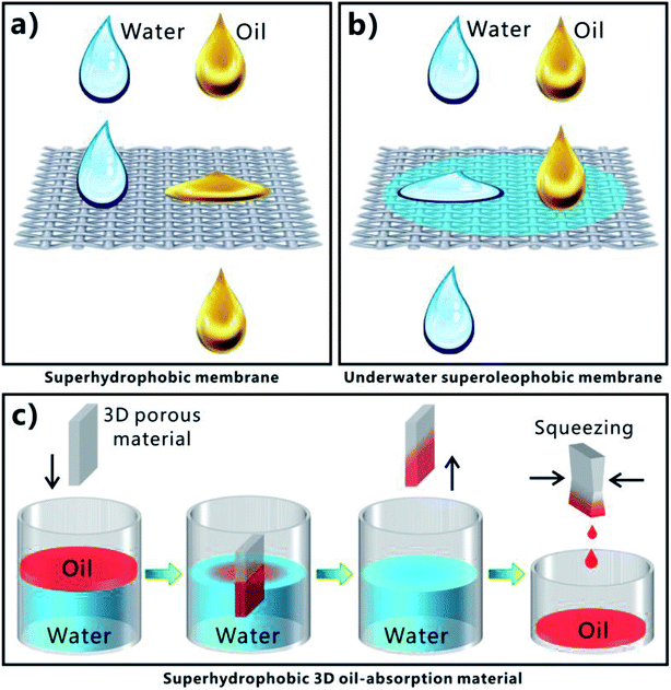
Extreme wettability and porous microstructure are necessary to achieve effective and repeatable OWS. Superhydrophobic porous membranes, underwater superoleophobic porous membranes, and superhydrophobic three-dimensional (3D) porous oil absorbent are three most commonly used superwetting materials in highly efficient OWS.1–5,11–33 Fig. 6a displays the process of separating the OWM by using a superhydrophobic but superoleophilic porous membrane (such as metal meshes, fabrics, fibers, polymer membranes, etc.). The oil phase in the mixture is able to wet and penetrate through the membrane driven by superoleophilicity and gravity force, while water phase is prevented from passing through this membrane due to the superhydrophobicity of the membrane surface.11–18,37,44,172–183 As a result, oil is removed from the mixture; that is, the OWM is separated. Regarding the underwater superoleophobic porous membranes (such as metal meshes, fabrics, fibers, polymer membranes, etc.), their surfaces usually show superhydrophilicity (or strong hydrophilicity) in air besides the superoleophobicity in water, according to the formation principle of underwater superoleophobicity. Once the OWM is poured onto such membrane that is previously wetted by water, superhydrophilicity will lead the water in the mixture to permeate through the membrane (Fig. 6b). On the contrary, oil phase is repelled by the pre-wetted membrane because of underwater superoleophobicity, so oil always stays on the membrane.6,7,19,21,22,24–29,35,38–43,120,184–188 Therefore, water in the mixture is removed, leaving only oil. Achieving OWS by using two-dimensional (2D) porous superhydrophobic or underwater superoleophobic membrane is indeed the filtering method. However, the above two separating ways are very difficult or even are impossible to solve the oil-polluted water in some special cases, such as a small amount of oil being leaked to sea surface and the case of leaked heavy oils on the seafloor. Fortunately, those special cases can be addressed by the superhydrophobic/superoleophilic 3D porous bulk materials (such as sponge, foam, aerogel, etc.) that can directly absorb and remove oils from water based on an absorption way. As shown in Fig. 6c, when such porous materials come in contact with the OWM, superoleophilicity and capillary action allow the oil phase in the mixture to be absorbed and enter into the inner space of the 3D porous materials. On the contrary, the water phase is repelled by the materials due to their superhydrophobic surfaces. Only oil phase is selectively absorbed by the 3D porous materials.13,20,23,30–33,189–203 As the materials are taken out of the mixture liquid, the oil phase is also taken away by the superhydrophobic 3D porous materials, so the oil part in the mixture is removed. The absorbed oil can be easily released and collected for reuse by squeezing the oil-filled porous materials. Particularly, the superhydrophobic 3D materials can completely remove the oils both on water surface and underwater. Of course, the reported superwetting materials and the separating ways used in OWS are not limited to the above-mentioned three types.1–5 The OWM is often diverse, including the cases of oils on water surface, oils underwater, water-in-oil emulsion, oil-in-water emulsion, and so on. To perform efficient OWS, the separating materials should give play to their respective characteristics in structure and wettability, depending on the different types and properties of the OWMs.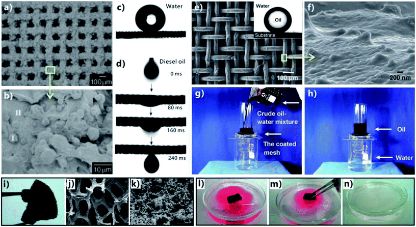 | ||
| Fig. 7 OWS by using different superwetting porous materials. (a and b) Surface microstructure of the PTFE-coated mesh. (c) Water droplet on the resultant superhydrophobic mesh. (d) Oil droplet wetting and passing through the PTFE-coated mesh. (e and f) Surface microstructure of the hydrogel-coated mesh. Inset: oil droplet on the underwater superoleophobic mesh in water. (g and h) Separation of water and crude oil by a pre-wetted hydrogel-coated mesh. (i) Photography of the as-prepared superhydrophobic sponge. (j and k) SEM images of the superhydrophobic sponge. (i–n) Process of absorbing and removing oil from water via the superhydrophobic/superoleophilic sponge. (a–d) Reproduced from ref. 11 with permission from Wiley, copyright 2004. (e–h) Reproduced from ref. 19 with permission from Wiley, copyright 2011. (i–n) Reproduced from ref. 20 with permission from ACS, copyright 2011. | ||
Gao et al. fabricated superhydrophobic foams by in situ Glaser–Hay coupling reaction and polydimethylsiloxane (PDMS) coating treatment.172 Copper foam was used as the substrate because it not only could act as the catalyst for the graphdiyne synthesis but also had inherent porous skeleton. The whole surface of the resultant copper skeleton was covered by vertical honeycomb-like nanoscale graphdiyne. The thin film of the as-prepared superhydrophobic foam exhibited great performance in OWS, with only allowing oils to pass through. Cao et al. coated a stainless steel mesh with polydopamine through immersing in an aqueous solution of dopamine and then used n-dodecyl mercaptan to conjugate with the polydopamine film by the Michael addition reaction.44 The as-prepared mesh exhibited high level of hydrophobicity and superoleophilicity, and could separate various mixtures of water and oils like diesel, gasoline, etc. Yu et al. roughened a stainless steel mesh by growing highly dense boron nitride nanotubes on its surface.37 The nanotubes with the diameter of 100–400 nm enhanced the wettability of the mesh from intrinsic hydrophobicity to superhydrophobicity. By using the nanotubes-coated mesh as a filter membrane, oil could be efficiently separated from water in oily sewerage. Zhou et al. reported a simple in situ vapor phase deposition route to fabricate superhydrophobic cotton fabrics for the application of OWS.173 The obtained fabrics allowed the permeation of oils but resisted water. Particularly, the oil/water separating fabrics still had high efficiency even under harsh conditions (e.g., strong acidic/alkaline solution, high temperature, mechanical forces, and high humidity). Li et al. obtained a superhydrophobic/superoleophilic hybrid mesh through the deposition of candle soot and hydrophobic silica nanoparticles on a stainless steel mesh.18 The membrane showed excellent water repellency to even corrosive and hot liquids. Therefore, it was able to separate different mixtures of oils and hot water or strong acidic/alkaline/salty solutions. Zhou et al. prepared a kind of titanium dioxide nanorods-structured copper foams by hydrothermal deposition.174 Both water and oil could easily wet and be absorbed by the resultant foam. However, the foam was superhydrophobic underwater oil. If a thin film of the underoil superhydrophobic foam was previously wetted by oil and then the OWM was poured onto this film, oil phase would penetrate through the pre-wetted film while water phase would retain above the film all the time. Wang et al. made a small oil containment boom which could separate and collect oils from water surface.175 A rough layer of Cu2O microstructure was first deposited onto the surface of a copper mesh by an electrodeposition process. The resultant mesh had all the features of porosity, superoleophilicity, and superhydrophobicity. Then, the mesh sheet was enfolded into a small box. Once the containment boom came in contact with the oil floating on water, the oil slick would instantly penetrate through the box's side walls and gather into the containment boom, whereas water would be strongly repelled out of the box. As a result, the oil pollutant was removed, achieving OWS.
Wen et al. endowed a metallic mesh with excellent superhydrophilicity and underwater superoleophobicity by growing a zeolite coating on the mesh surface.22 Various oils could be separated from water by using such zeolite-coated mesh. Li et al. coated a copper mesh with a layer of palygorskite by spraying the mixture consisting of palygorskite powders and waterborne polyurethane onto the mesh's surface.42 The excellent environmental stability allowed the as-prepared underwater superoleophobic mesh to separate a series of mixtures of oil and various corrosive acidic, alkaline, salt, or hot water solutions. Yong et al. found that sand layer had strong ability of absorbing water and exhibited (quasi-) superoleophobicity and extremely low adhesion to various oil droplets in water.6 The pre-wetted superhydrophilic and underwater superoleophobic sand layer was applied in OWS with high efficiency and wonderful separation capacity. Since the sand particles used in OWS can be directly obtained from the desert without any other treatment, this sand-based separating route is low cost, green, eco-friendly, and has the potential for large-scale application. The water-wetted natural wood sheets could also be used to separate OWMs.7 Li et al. prepared hierarchical TiO2 nanotubes on a porous titanium substrate by electrochemical treatment and subsequent calcination in air.38 The porous film with underwater superoleophobicity could achieve OWS as it only permitted water to penetrate through. Moreover, once the material was polluted by organic contaminant during OWS, the special surface wettability could be recovered via UV treatment because the photocatalysis of the hierarchical TiO2 nanotubes was able to decompose the toxic organic molecules under UV light. Such UV-induced self-cleaning was essentially important for the as-prepared material towards OWS. Dong et al. coated a stainless steel mesh with hydrophilic graphene oxide (GO) nanosheets.41 Because of the completely opposite wettability (i.e., in-air superhydrophilicity and in-water superoleophobicity) to water and oil, the GO-coated mesh was successfully applied in gravity-driven OWS. Zwitterionic poly(sulfobetaine methacrylate) (pSBMA) can strongly interact with water by electrostatic interactions, so it is a kind of typical superhydrophilic polymer. Liu et al. used the method of surface-initiated atom transfer radical polymerization to graft pSBMA onto the surface of glass fibers.184 The pSBMA-grafted glass slide was underwater superoleophobic and showed great ability to separate oil from water. Cheng et al. developed a pH-controllable OWS based on the metal mesh that was integrated the Cu(OH)2 nanorods and the assembled responsive thiol molecules on a copper mesh.43 The as-prepared mesh showed superhydrophobicity to non-alkaline water droplet but superhydrophilicity to alkaline water droplet. Meanwhile, the mesh was superoleophobic in alkaline water. With such mesh as the filter, the process of separating OWM could be triggered by increasing the pH of the water in the mixture. Zhang et al. fabricated a poly-(acrylic acid)-grafted poly(vinylidene fluoride) separating film by a salt-based phase-inversion method.39 The formation of a hierarchical microstructure endowed the membrane with superhydrophilicity and underwater superoleophobicity. Both the surfactant-stabilized/-free oil-in-water emulsions could be efficiently separated using the resultant membrane.
Typically, the superhydrophobic/oleophilic porous membranes achieve oil/water separation by unidirectional oil transportation and intercepting water; whereas the underwater superoleophobic membranes separate oil from water by discharging just water, because light oils cannot penetrate through the superoleophobic water/membrane interface. However, both of these kinds of separating mesh/membranes are not universally applicable. Each kind of mesh is only suitable for a certain case based on the comparison between oil density and water density. Furthermore, both of them are unable to realize unidirectional transport of water or oils. Inverse flow usually results in poor separation selectivity and low the separation efficiency in the real separation process. Recently, Janus membranes with asymmetric superwettabilities on both sides have emerged as a solution to the above-mentioned problems.204–208 For example, Cheng et al. obtained a Cu(OH)2 nanowires-structured mesh with asymmetric wetting performance: one side shows hydrophilicity and the other shows hydrophobicity.204 The film was prepared by single-face modification of the textured metal mesh with the low-surface-energy fluorosilane. Water can permeate from the hydrophobic side to the hydrophilic side, but is hindered in the opposite direction. Based on this special unidirectional water permeation property of the as-prepared Janus mesh, no matter the light oil/water mixtures (ρoil < ρwater) or the heavy oil/water mixtures (ρoil > ρwater) can be separated by simply changing the mesh direction. Regarding the light oil/water mixtures, water can pass through the mesh whereas oil is intercepted if the hydrophilic side faces the mixture. For heavy oil/water mixtures, oil can permeate the mesh and water is retained if the hydrophobic side faces the mixture. Gu et al. fabricated Janus hybrid membranes by respectively grafting hydrophobic polymer and hydrophilic polymer from different sides of carbon nanotube membranes via self-initiated photo-grafting and photo-polymerization.205 The resultant membranes with unique Janus wettability can effectively separate both surfactant-stabilized oil-in-water and water-in-oil emulsions. Wang et al. reported a Janus cotton fabric that was coated on one side by a hydrophobic polymer and on the other side by a polyamine.206 The Janus cotton fabric is superhydrophobic on one surface and polyamine-bearing on the other. Various oil/water mixtures as well as oil-in-water emulsions can be separated by using the as-prepared Janus fabrics as filters. Hu et al. prepared bilayer membranes that feature asymmetric wettability across the membrane thickness by depositing an ultrathin layer of polydopamine-coated single-walled carbon nanotubes on a porous solid substrate and subsequently coating with an ultrathin single-walled carbon nanotubes layer.207 By adjusting the applied pressure across the membrane, both surfactant-stabilized water-in-oil and oil-in-water emulsions can be selectively separated. Yun et al. fabricated GO sponges by freeze-drying method.208 The wettability of the GO sponge was further changed by oxygen (OGO, hydrophilic/oleophilic in air) or fluorine (F-GO, hydrophobic/oleophilic in air) functionalization. The obtained Janus GO was successfully applied to separate both water-in-oil and oil-in-water emulsions by changing the flow direction.
Cui et al. synthesized a sponge-like bulk material that was made up of interconnected carbon nanotubes skeletons.189 The sponge had many features such as very low density, a porosity of >99%, high flexibility, and superhydrophobicity. The sponge could absorb different oils and organic solvents with remarkable selectivity. The absorption capacity reached up to 800 times the weight of the bulk material, as the sponge could swell instantaneously upon contact with oils. The as-prepared sponge could be potentially applied in large-area spill cleanup by quickly remove the spreading oil film on water surface. Li et al. prepared a superhydrophobic attapulgite-coated polyurethane sponge via an ultrasonic dip-coating process.190 The sponge was able to absorb a wide range of oils from water surfaces, even though the oils floated on hot water or corrosive aqueous solutions. As a result, the oils were removed from water surface. Hou et al. obtained the micro/nanoscale aggregations of poly((3,3,3-trifluoropropyl)methylsiloxane) dispersed in acetone/water through a phase separation technology.191 The aggregations could be deposited on the skeletons of different porous 2D and 3D substrates through different typical coating processes, resulting in the superhydrophobicity of those porous materials due to the aggregation-induced rough surface morphology and low surface energy. The as-prepared superhydrophobic porous materials had strong ability to separate OWM. For example, a coated sponge could absorb oils from water surface but repel water. Carbon soot is a common daily waste. Gao et al. reported a cost-effective oil-absorbent by coating a melamine sponge with carbon soot.192 Oil contaminants could be completely removed from water by the absorbent. The carbon soot was obtained from a combustion flame, and the soot-coated sponge was synthesized by a simple dip-coating way. Zhao et al. obtained a superhydrophobic/superoleophilic PDMS sponge by the polymerization of pre-polymer and curing agent in dimethicone.193 The microscale NaCl particles were adopted as the template. The as-prepared porous sponge presented high compressibility, stretchability, and chemical and thermal stability. The special wettability allowed the PDMS sponge to selectively absorb the oils either floating on water surface (light oil) or underwater (heavy oil). Du et al. designed multi-dimensional and well-defined magnetic microstructure on the surface of a melamine foam via the controlled precipitation and reductive annealing treatment.194 The as-prepared foam also had magnetic-driven property in addition to the superhydrophobicity and superoleophilicity. Therefore, the superhydrophobic foam could achieve remote-controllability OWS, whose movement was controlled by magnetism. In fact, sometimes the 2D superhydrophobic porous mesh/membrane can also be transformed into different kind of 3D oil absorbents. Song et al. prepared a 3D floating-oil collection prototype device by using 2D superhydrophobic and superoleophilic metallic mesh.13 Such mesh was capped on the open end of a glass beaker through a leak-proof manner. The beaker was partly immersed into a floating OWM in a tilted fashion, ensuring that part of the mesh contacted with the OWM and another part was exposed in air. The floating oil film could easily wet and penetrate through the mesh, and finally enter into and be collected by the beaker, driven by the mesh's superhydrophilicity. Whereas, the water phase was completely repelled by the mesh and remained outside of the collection device.
3. Oil/water separation
3.1 Superhydrophobic porous membrane
Yong et al. obtained a superhydrophobic PTFE surface by a one-step fs treatment.16,77 The PTFE sample was simply ablated by fs laser based on the typical LBL scanning manner. After laser ablation, there were abundant pores and protrusions forming on the PTFE surface (Fig. 8a–c). The pores were interconnected with each other, like an ant nest. The protrusions were 300 nm to 2 μm in size. Water droplets on the textured PTFE showed a WCA of 155.5° (Fig. 8d and e) and could roll off once the sample was tilted 2.5° (Fig. 8f), indicating that the hydrophobicity of the PTFE material was amplified by the surface roughness resulted from laser ablation. Such fs laser-structured surface exhibited both superhydrophobicity and ultralow adhesion to water droplets because water droplets were at the Cassie wetting state on the microstructure. Different from the water wettability, the resultant rough PTFE surface showed superoleophilicity to an oil droplet. Once an oil (petroleum ether) droplet came in contact with the sample surface, the oil would spread out and wet the laser-structured area in a very short time (Fig. 8d). The measured OCA was close to 0°. In general, rough microstructures have the ability to amplify surface wettability of solid materials, so the PTFE substrate was changed from intrinsic hydrophobicity (WCA = 111.5°) and oleophilicity (OCA = 10.4° to petroleum ether) to contrasting superhydrophobicity and superoleophilicity by fs laser treatment.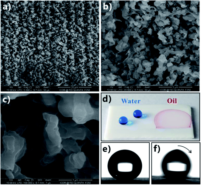 | ||
| Fig. 8 Superhydrophobicity and superoleophilicity of the PTFE surface after fs laser ablation. (a–c) Surface microstructure. (d) Photography of water (blue color) and oil (red color) droplets on the as-prepared PTFE surface. (e) Static shape and (f) roll behavior of a water droplet on the laser-structured surface. Reproduced from ref. 16 with permission from Elsevier, copyright 2016. | ||
Taking advantages of the superhydrophobicity and superoleophilicity of the fs laser-structured PTFE surface, Yong et al. further fabricated a superhydrophobic porous PTFE sheet by the combination of fs laser treatment and mechanical drilling method and then achieved OWS.16 The surface of the PTFE sheet (thickness = 300 μm) was firstly ablated by fs laser to form a layer of rough surface microstructures. Then, a microholes array through the sheet was generated on the laser ablated PTFE sheet by using a homemade mechanical drilling system consisting of a mini drill with 300 μm in drill bit diameter. The drill was controlled to pass through the thin sheet from the unablated side with the speed of 0.5 mm s−1, forming many ordered open microholes. Fig. 9a and b shows the surface microstructure of the resultant sheet. There was a microholes array uniformly distributing on the sheet. The diameter of the holes was 240–280 μm, with the extrusion and stretch occurring in the drilling process. The rest area between the microholes was characterized by rough microstructure resulted from laser ablation. When the unablated side of the sheet was exposed to a white light, the back-light could successfully pass through the holes but the rest domain still looked dark, with viewing from front side. The transparent region in Fig. 9c reveals that all of the drilled microholes were open. When oil droplets were dripped onto the porous rough PTFE sheet, the superoleophilicity allowed the oil droplets to fully wet the sample surface within only 20 ms (Fig. 9d). As the number of oil droplets increased, the oil finally penetrated through the PTFE sheet along the perforated microholes (Fig. 9d) and dropt down (Fig. 9e).
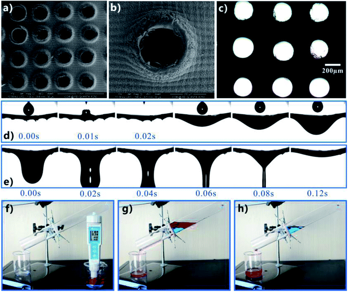 | ||
| Fig. 9 Separating the OWM by using the fs laser-structured porous PTFE sheet. (a and b) Surface morphology of the rough porous sheet. (c) Optical microscope image of the as-prepared sheet. The sample was irradiated by a beam of white light from its backside. (d and e) Continuously dripping oil droplets onto the rough porous PTFE sheet: (d) oil droplets wetting and penetrating through the sheet, (e) the penetrated oil dropping down. (f–h) Process of separating the mixture of water (blue color) and oil (red color): (f) before separation, (g) pouring the mixture into the separating device, (h) after separation. Reproduced from ref. 16 with permission from Elsevier, copyright 2016. | ||
The diametrically opposite wettability (i.e., superhydrophobicity and superoleophilicity) endowed the rough porous PTFE sheet with the ability to separate the OWM.16 As shown in Fig. 9f, a man-made simple separating device was assembled by using the as-prepared sheet as the separating membrane. The superhydrophobic porous sheet was sandwiched between two glass tubes. When the mixture of immiscible oil (petroleum ether, red color) and water (blue color) was poured into the upper tube of the designed device, only the oil phase passed through the PTFE sheet. In contrast, the water phase was intercepted and always stayed on the sheet (in the upper tube) even after that oil completely dropt into the below beaker. As a result, the OWM was successfully separated, just driven by gravity. Having superhydrophobicity and superoleophilicity simultaneously was essential for the porous PTFE surface to separate the mixture. Superhydrophobicity prevented the water part in the OWM from wetting the laser-induced surface microstructure, while superoleophilicity allowed the oil part to wet the surface microstructures and the microholes quickly and further penetrate through the PTFE sheet. By comparison, if the PTFE sheet with only microholes (without fs laser treatment) was used to perform such separation experiment, not only oil but also water was able to pass through the sheet.
It has been demonstrated that the fs laser-structured PTFE surface can maintain superhydrophobicity even in various harsh environments. In addition to the neutral mixture, the as-prepared rough porous PTFE sheet also can efficiently separate the mixtures of oils and different strong acid/alkali solutions. As shown in Fig. 10a–c, as the mixture of oil and HCl solution with the pH of 1 was added in the separating device, the oil phase would easily pass through the sheet while the water always remained in the upper tube, indicating that oil phase was removed from the acid mixture. Similarly, the mixture of oil and corrosive KOH solution (pH = 13) could also be separated through the same process (Fig. 10d–f). It can be predicted that this separation device is able to work in different harsh environments.
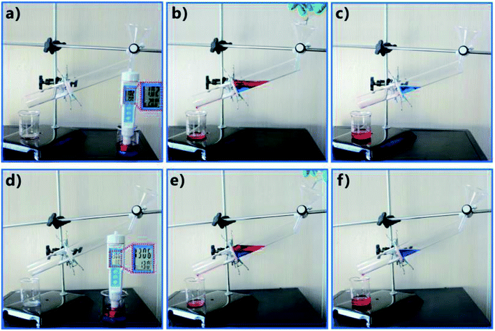 | ||
| Fig. 10 Separating different acid/alkali OWMs by using the fs laser-induced superhydrophobic porous PTFE sheet: the mixtures of oils and (a) HCl solution with the pH of 1 and (b) corrosive KOH solution with the pH of 13. (a and d) Before separation. (b and e) After adding OWM into the separating device. (c and f) After separation. Reproduced from ref. 16 with permission from Elsevier, copyright 2016. | ||
The separation of immiscible products from chemical reaction systems is a typical and important “oil/water separation” process in chemical industry. Xu et al. prepared a superwetting PTFE membrane with regular micro-porous array by using a laser PBP ablation method.209 The membrane exhibits highly hydrophobic/oleophilic in air and underwater superoleophilic. A continuous in situ separation of chemical reaction system was well conducted by using the functional membrane. They further applied the laser-treated porous membrane with superhydrophobicity and superoleophilicity in the continuous in situ extraction of multiphase complex systems.210
3.2 Underwater superoleophobic porous film
Li et al. fabricated a regular micropores array on the aluminum foil through the fs laser perforating process and further successfully achieved OWS by using the as-prepared porous foil.28 Fig. 11a shows the fabrication process. The fs laser beam was focused on the surface of an aluminum foil (thickness = 25 μm), with the diameter of focus spot being about 20 μm. The typical PBP ablating manner was adopted and the location of the ablating point was controlled by a galvanometer scanner. For example, just 4–5 pulses could burn through the thin aluminum foil at the laser pulse energy of 50 μJ. A brilliant iridescence was presented by the fabricated aluminum foil when the sample was illuminated by white light, resulting from the light diffraction (Fig. 11b). The SEM image reveals that a uniform array of microscale pores was created on the aluminum foil surface (Fig. 11c). The rim and inside wall of every micropore were further coated with fine nanostructures (Fig. 11d). It was demonstrated that all of the laser-drilled pores were opening from the transmission microscope photograph (inset of Fig. 11c). Further experiment revealed that the diameter of the pores could be easily tuned in the range of 2.4 to 32 μm by adjusting laser power and pulse numbers. The combination of the microscale pores and the nanoscale roughness enhanced the surface wettability of the foil from intrinsic ordinary hydrophilicity with a WCA of 53.9° to superhydrophilicity with a WCA of 7.8° (Fig. 11e). After the immersion of the microporous aluminum foil in water, superoleophobicity was exhibited by the foil with the OCA values of 153.5° and 153.1° to a normal octane droplet (Fig. 11f) and a 1,2-dichloroethane droplet (Fig. 11g), respectively. With increasing the diameter or decreasing the interval of the generated micropores, it was found that the foil became more hydrophilic and more oleophobic in water. The contrary wettabilities for oil and water allowed the as-prepared foil to separate OWM. The separating device in Fig. 11h was used the as-prepared porous aluminum foil (micropores' diameter = 8.2 μm, micropores' interval = 60 μm) as the separating membrane. The membrane was pre-wetted with water and was horizontally sandwiched between a tube and a conical flask. When the mixture of light oil (octane, red color) and water (blue color) was poured into this device, water instantly started penetrating through the micropores by the superhydrophilicity of the laser-induced porous aluminum foil and the gravity force. In contrast, oil was blocked above the underwater superoleophobic aluminum foil (Fig. 11h and i). Such separation process could finish within 13 s and no extra force was needed apart from gravity.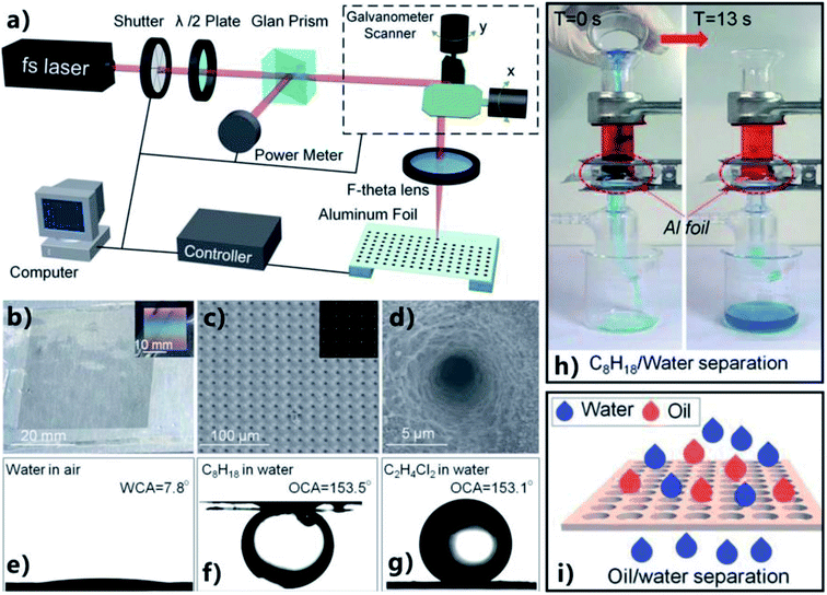 | ||
| Fig. 11 OWS by using the porous thin aluminum foil obtained by the fs laser perforating process. (a) Schematic of the preparation process. (b) Optical photography of the porous foil. The inset shows the brilliant iridescence on the aluminum foil under the white light incidence. (c and d) SEM images of the porous foil. Inset in (c): the transmission microscope photograph of the porous foil. (e–g) Different liquid droplets on the porous surface: (e) water droplet in air, (f) underwater octane droplet, and (g) underwater 1,2-dichloroethane droplet. (h) Separating the mixture of water (blue color) and octane (red color) by a pre-wetted porous aluminum foil as the separating membrane. (i) Schematic of the separation process. Reproduced from ref. 28 with permission from RSC, copyright 2016. | ||
Ye et al. also prepared an underwater superoleophobic perforating titanium foil by fs laser micro-drilling, which was successfully applied in OWS.78 After fs laser treatment, an array of funnel-shaped through microholes was formed on the foil. The diameter of the fs laser-induced microholes was about 55 μm fabricated at the laser fluence of 12.4 J cm−2, and enlarged with increasing the laser fluence. The wall of every microhole was fully decorated with irregular nanoscale protrusions with the size of several hundred nanometers. The oxidization of the Ti substrate during fs laser ablation was also detected. The resultant microholes-structured foil showed superhydrophilicity with a WCA near 0° in air and superoleophobicity with an OCA of 159.6° in water. After the mixture of water and sesame oil being poured onto the pre-water-wetted porous foil, the water in the mixture quickly penetrated through the filter and the oil was retained above the foil due to its underwater oil repellency.
Fabrication of micro-through-hole structures usually makes the preparation process become complicated, high-cost, and time-consuming. In some cases, the inherent microholes of the porous substrates can be directly utilized. Yin et al. fabricated an oil/water separating mesh by one-step fs ablation without the further process of the generation of microholes.79 The pores of the metal mesh served as the through microholes of the separating membrane. A stainless steel mesh was simply ablated by the fs laser based on the LBL scanning manner. The laser beam (power = 7 W) was focused on the mesh surface through an F-theta lens (f = 100 mm). Fs laser treatment led the color of the mesh (300 mesh) to change from brilliant silver to black, resulted from the formation of the nanostructures on the mesh surface. There were uniform periodic nanoscale ripples with the period of about 500–800 nm covering on the wire surface (Fig. 12a). The average depth of the nanoripples was 130 nm. Such nanoripple is one of the typical results of fs laser–solid interaction. The surface of the nanoripples was further decorated with plenty of nanoscale particles with the size ranging from tens to hundreds of nanometers (Fig. 12b). The mesh was also oxidized during laser irradiation because new element O with the element weight of 6.37% emerged. The fs laser-induced uniform nanoripple structures and the oxidation turned the wettability of the stainless steel mesh from hydrophobicity (for the pristine mesh) to superhydrophilicity with the WCA of near 0° (Fig. 12c). When the laser-ablated mesh was immersed in water and an 1,2-dichloroethane droplet was placed on the mesh surface, underwater superoleophobicity was exhibited by the mesh with an OCA of 157° (Fig. 12d). The as-prepared mesh also showed ultralow oil-adhesion since the oil droplet could roll away as long as the mesh was tilted about 5°. Fig. 12e displays the process of separating an OWM by using the laser-structured mesh. The superhydrophilic and underwater superoleophobic mesh was wetted by water in advance and placed over two beakers. The right beaker was higher than the left one, making the mesh have a tilted angle of ∼25°. As the OWM was poured onto the pre-wetted rough mesh, water (blue color) penetrated through the superhydrophilic mesh and dropt into the right collecting beaker. By contrast, diesel oil (red color) quickly flowed over the mesh and finally was collected by the left beaker under the force of gravity. As a result, the mixture was completely separated. Further experiment revealed that the laser treated mesh exhibited a universal underwater superoleophobicity regardless of the oil type and the measured separation efficiency was above 99% for different types of OWMs by using the as-prepared mesh as the separating membrane.
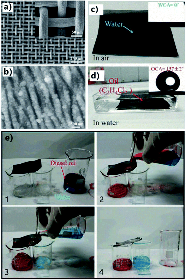 | ||
| Fig. 12 OWS by using the fs laser-structured stainless steel mesh. (a and b) Surface microstructure of the mesh after fs laser ablation. (c) Water droplet on the resultant mesh in air. (d) Oil droplet on the rough mesh in water. (e) Process of separating an OWM by using the laser-structured mesh. Reproduced from ref. 79 with permission from RSC, copyright 2017. | ||
3.3 Janus film
According to the category of surface wettability, superhydrophobic separating filter and underwater superoleophobic separating filter are introduced in the above sections, respectively. To achieve efficient OWS, the former allows oil to permeate through but blocks water due to its superhydrophobicity, whereas the latter just allows water to pass through but intercepts oil due to the underwater superoleophobicity. It can be found that both of such two separating films are not universally applicable. Each separating material is only suitable for a certain case.11,19 For the simplest separating device fabricated by horizontally sandwiched a superwetting porous membrane between two tubes, the superhydrophobic membrane is suit to separate the mixture of heavy oils and water, while the underwater superoleophobic membrane is suit to separate the mixture of light oils and water. Furthermore, those separating membranes are not able to allow oils or water to unidirectionally pass through. The inverse flow in a real separation usually happens and results in low separation efficiency and poor separation selectivity. To solve the above-mentioned problems, some Janus membranes with asymmetric surface microstructures and wettabilities were fabricated.211 For instance, Liu et al. reported a Janus metal mesh that was prepared by fs laser treatment and selectively modifying the two sides with fluoroalkylsilane and GO, respectively.80 Fig. 13a depicts the fabrication process of the Janus mesh. Firstly, the front side of a copper mesh (side length of the square pores = 150 μm, diameter of the wire = 100 μm) was ablated by fs laser at the laser power of 580 mW (7.39 × 10³ J m−2). The treatment of fs laser ablation induced the generation of LIPSS with the period of 900 nm on the front surface of the mesh (Fig. 13b). Secondly, the mesh was treated by fluoroalkylsilane modification to allow the front side to have superhydrophobicity. Water droplet on such front mesh surface showed a WCA of 160° (inset of Fig. 13a) and could roll away on the 2° tilted mesh (Fig. 13h), while oil droplet directly spread out the front mesh after coming in contact with the mesh (Fig. 13i). Thirdly, the mesh's backside was ablated by fs laser at a relatively low laser power (100 mW, 1.27 × 10³ J m−2) to not only remove the residual fluoroalkylsilane on the backside but also generate worm-like ripples on the back surface of the mesh (Fig. 13c). Finally, the rough back side was modified with a layer of GO via the dip coating method, ensuring that the worm-like nanoripples were well identified from the laser-treated substrate. Since the GO was rich in hydrophilic oxygen groups (such as hydroxyl and carboxyl groups), the back surface of the resultant mesh became superhydrophilic in air (Fig. 13j). After the immersion of the mesh in water, the back side exhibited superoleophobicity with OCA of 161° to an n-hexane droplet (inset of Fig. 13a). Underwater oil droplet could also easily roll off the back side of the mesh with a slight tilted angle (Fig. 13k). Therefore, the as-prepared mesh showed Janus wettability because its one side was superhydrophobic/superoleophilic and another side was superhydrophilic/underwater superoleophobic.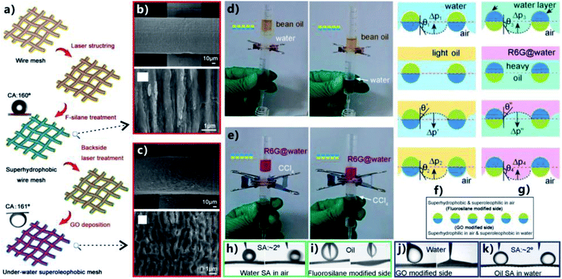 | ||
| Fig. 13 Selective OWS by using a laser-structured Janus mesh. (a) Schematic diagram of the process of fabricating the Janus mesh. Upper inset shows an in-air water droplet on the fluoroalkylsilane modified side and the lower inset presents an underwater oil droplet on the GO modified side. (b) SEM image of the fluoroalkylsilane modified side of the mesh. (c) Surface microstructure of the GO modified side of the mesh. (d) Separation of the mixture of water and light oil (bean oil) by the Janus mesh with the fluoroalkylsilane modified side facing upward. (e) Separation of the mixture of water (pink color) and heavy oil (CCl4) by the Janus mesh with the GO modified side facing upward. (f and g) Schematic of the selective separation process: (f) separating the mixture of water and light oil, (g) separating the mixture of water and heavy oil. (h) Water droplet rolling on the fluoroalkylsilane modified mesh. (i) Oil wetting the fluoroalkylsilane modified mesh in air. (j) Water wetting the GO modified mesh. (k) Underwater oil droplet rolling on the GO modified mesh. Reproduced from ref. 80 with permission from RSC, copyright 2017. | ||
By using the Janus mesh, selective gravity-driven separation of the mixtures of water and no matter heavy or light oils was achieved. They found the intrusion pressure played a significant role in different types of OWS. In the case of a light oil (bean oil), the mesh was sandwiched between two plastic tubes and the fluoroalkylsilane modified side faced upward. After the OWM being added into the separating device, it could be observed that only water passed through the Janus mesh (Fig. 13d). As shown in Fig. 13f, the superhydrophobic side was firstly contact with the mixture. There was a hydrostatic pressure pushing the water to penetrate the mesh but a hydrophobic force resisting this penetration. For a much small hydrostatic pressure, the separation would not start because the superhydrophobicity prevented the mixture from permeating through the mesh. Therefore, the hydrostatic pressure must be large enough. When water penetrated into the pores of the mesh deeply and made in contact with the hydrophilic region beneath, the water would entirely pass through the mesh and fully wetted the superhydrophilic side by the capillary effect, forming a water layer on the superhydrophilic side beneath. Oil was able to wet the superhydrophobic side of the Janus mesh but was blocked by the superhydrophilic/underwater superoleophobic side, so the mesh could support a certain height of the oils. Regarding the mixture of water and heavy oils (e.g., CCl4), the GO modified side needed to face upward, allowing the oil to first contact with the mesh. It could be observed that only oil phase in the mixture could pass through the Janus mesh (Fig. 13e). As shown in Fig. 13g, the oil was able to wet the surface and penetrate easily due to the in-air oleophilicity of both the GO modified side and the fluoroalkylsilane modified side. When the water phase also touched the oil-wetted mesh, it wet the GO modified side due to the superhydrophilicity but did not pass through the superhydrophobic below half part. The mesh could support a certain pressure of water. Therefore, both the light OWM and the heavy OWM can be selectively separated as long as a proper side of the Janus mesh faces up.
Although many Janus membranes with asymmetric wettabilities have been reported and applied in oil/water separation, in most cases, the Janus membranes are prepared by the selective modification of one side, sequential decoration, or directly combining two membranes together.204–208 Compared to the common methods, fs laser microfabrication is able to get precise control over the surface micro/nanostructures and the chemical composition on both sides of porous mesh/membranes synchronously, which shows great advantages in achieving distinct wetting behaviors on the two sides of the Janus membrane.
3.4 Selective oil/water separation
Lian et al. reported a simple method to realize selective light or heavy OWS by using the nanosecond laser ablated brass mesh.81 A low-cost nanosecond laser marking system (pulse width of 100 ns, Q frequency = 20 kHz) was adopted to generate rough texture on the surface of the mesh based on the LBL scanning process. The surface of the original bare brass mesh (200 mesh size) is smooth (Fig. 14a). The nanosecond laser ablation resulted in a coating layer of micro/nanoscale binary structure on the wire of the mesh (Fig. 14b). The pore size of the mesh also decreased from 75 μm to 65 μm due to the formation of the rough surface microstructures on the wires (Fig. 14a and b). In addition, O element was found to appear on the resultant surface, indicating that metal oxidation happened during laser ablation. Laser ablation made the mesh exhibit superhydrophilicity and superoleophilicity simultaneously in air. When water and oil (kerosene) droplets was dripped onto the resultant mesh, they would spread out quickly after just contact, resulting in a WCA below 10° and an OCA of about 0°. If the mesh was immersed in liquid phase, the wettability of the as-prepared mesh would change obviously. Fig. 14c shows an oil (1,2-dichloroethane) droplet on the laser-treated mesh underwater. The oil droplet looked like a sphere with an OCA of 157.5°, revealing that the mesh was superoleophobic in water. The superoleophobicity was ascribed to the underwater Cassie wetting of the oil on the rough mesh. Similarly, for the case of the rough mesh in oil (kerosene), water droplet that was put on the mesh showed a WCA of 156.3°; that is, the laser-treated mesh also had underoil superhydrophobicity (Fig. 14d). When the rough mesh was submerged in oil, the oil would rapidly wet the mesh due to the superoleophilicity of the mesh and an oil layer would be trapped in the hierarchical microstructures. The underoil water droplets on the mesh were strongly repelled by such trapped oil cushion which dramatically decreased the contact area between the mesh surface and the water droplets, resulting in the underoil superhydrophobicity of the textured mesh. The underwater superoleophobicity as well as the underoil superhydrophobicity of the laser-ablated mesh was valid for many different oils, including kerosene, soybean oil, dodecane, chloroform, and 1,2-dichloroethane. Based on the special wettability (underwater superoleophobicity and underoil superhydrophobicity), the resultant mesh was able to selectively separate the light or heavy OWMs. The separating device may not seem very different from the above-mentioned setup by sandwiching the separating membrane between two tubes (Fig. 14e and f). The key here is to correctly wet the mesh in advance. Regarding the mixture of kerosene (light oil) and water, the mesh needed to be previously wetted by a little water. When the mixture was added into the upper tube, only the water phase in the mixture could pass through the pre-wetted mesh and be collected in the below container while the oil phase was held back (Fig. 14e). After the separation, the mesh was cleaned with ethanol and was able to further separate the mixture of 1,2-dichloroethane (heavy oil) and water. In this case, the mesh needed to be wetted by a small amount of oil. After the mixture being added into the separating device, the oil could penetrate through the pre-wetted mesh, and there was no water appearing in the collected oil (Fig. 14f). Also, the mesh was easily switched to separate light OWM again after cleaning with ethanol. The underwater superoleophobicity endowed the water-wetted mesh with the ability to separate light OWMs, whereas the underoil superhydrophobicity allowed the oil-wetted mesh to separate heavy OWMs. The switch between those two separating ways could be repeated for at least five cycles with high separation efficiency.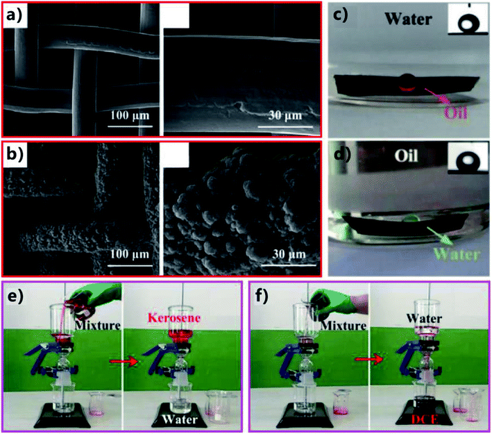 | ||
| Fig. 14 Selective OWS by using the nanosecond laser-ablated brass mesh as the separating membrane. (a) Morphology of the untreated bare brass mesh. (b) Surface microstructure of the brass mesh after nanosecond laser treatment. (c) Underwater superoleophobicity of the laser-induced rough mesh. (d) Underoil superhydrophobicity of the rough mesh. (e) Separation of light oil (kerosene) and water by using the water-wetted rough mesh. (f) Separation of heavy oil (1,2-dichloroethane) and water by using the oil-wetted rough mesh. Reproduced from ref. 81 with permission from ACS, copyright 2018. | ||
Although nanosecond laser was utilized to rough the mesh surface in the above example, we believe the surface microstructures and the special wettability can also be created by fs laser through the same treatment. The fs laser-textured mesh with underwater superoleophobicity and underoil superhydrophobicity is also able to selectively separate OWM, like the above example. Therefore, we loosely introduce this example here and we can predict that the similar method for selective OWS based on the fs laser-induced super-wetting porous materials will be reported within the next year or two.
3.5 Oil-absorption 3D materials
Different from the superwetting separating mesh/membranes, superhydrophobic and superoleophilic 3D porous bulk materials can directly absorb oils from no matter water surface or underwater, thereby the contaminated oils are completely removed from the OWM and be collected for reuse.190,192,195–203 Oil-absorption 3D materials are better than separating membranes in some special cases towards achieving efficient OWS, such as leaked heavy oils, a small amount of oil being leaked to sea surface, etc. However, laser ablation is not suit to process uneven surface, especially for 3D materials such as foam, sponge, etc. Fortunately, 2D membrane can be folded into a 3D shape, similar to origami. Zhang et al. proposed a method to make the fs laser-structured 2D foil become a 3D oil-absorption barrel.62 They fabricated a tapered microholes-structured Janus oil barrel by fs laser micro-drilling, fluoroalkylsilane modification, laser scanning the lower surface, and assembling. Such novel oil barrel had a superhydrophilic inside wall and a superhydrophobic outside wall, which could efficiently remove oil from water surface. Fig. 15a shows the preparation process. Firstly, a uniform microholes array was fabricated on an aluminum foil by using fs laser micro-drilling (i.e., PBP ablation) (Step 1). The location of the ablation points was precisely controlled by a high-speed galvanometer scanner. The diameter of the focus spot of the fs laser beam was ∼20 μm, and that of the generated microholes could be adjusted from 14.05 to 31.3 μm by changing the laser pulse energy and the pulse number. The period of the microholes array was set at 100 μm. Both the upper and the lower surfaces of the treated aluminum foil showed superhydrophilicity after laser drilling (left column of Fig. 15c). Secondly, the wettability of the foil was switched from superhydrophilicity to superhydrophobicity by the fluoroalkylsilane modification (Step 2). As a result, the water droplets on the upper surface and lower surface of the foil had the WCA values of 166.7° and 158.4°, respectively (middle column of Fig. 15c). After that, only the lower surface was ablated by fs laser via the LBL scanning process (Step 3). Such treatment is a means to remove the fluorination composition on the lower surface. Fig. 15b shows the microstructures of both side of the as-prepared foil, respectively. Surrounding area of the microholes on the upper surface was completely covered with microscale fragments (2 to 10 μm), while that on the lower surface was covered with nanoscale protuberances (0.2 to 1 μm). The cross-section SEM image shows that the fabricated microholes had a tapered morphology with the taper angle of 25–30°, resulting from the Gaussian laser ablation (inset of Fig. 15a). There were a lot of micro/nanoscale wrinkles distributing on the microholes' inner wall. After the 3rd step, the upper surface maintained its superhydrophobicity with the WCA of 158.4° but the lower surface changed to superhydrophilicity with the WCA of 4.2° (right column of Fig. 15c). In addition, the upper surface exhibited superoleophilicity (OCA = 5.4°) in air, and the lower surface exhibited superoleophilicity (OCA = ∼0°) in air and underwater superoleophobicity (OCA = ∼150.7°). As a result, the as-prepared aluminum foil had not only different surface microstructures but also different surface wettabilities on both sides, showing a Janus feature.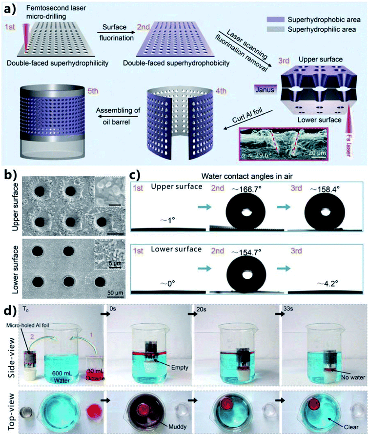 | ||
| Fig. 15 Oil absorption based on a Janus oil barrel (superhydrophilic inside wall and superhydrophobic outside wall). (a) Preparation process of the Janus oil barrel: Step 1, fs laser micro-drilling; Step 2, fluoroalkylsilane modification; Step 3, laser scanning on the lower surface; and Step 4 and 5, assembling. (b) SEM images of the two side of the resultant aluminum foil. (c) Water contact angles of the treated upper surface and the lower surface after different steps. (d) Process of absorbing oil from water surface by using the Janus oil barrel. Reproduced from ref. 62 with permission from RSC, copyright 2017. | ||
An oil barrel was easily assembled by curling the flexible Janus porous aluminum foil (4th and 5th steps in Fig. 15a). The as-prepared Janus barrel had a superhydrophobic/superoleophilic outside wall and a superhydrophilic/underwater superoleophobic inside wall. Such Janus barrel showed great oil-absorption and storage capacity towards collecting spilled oil. The inside wall was pre-wetted by a little water before use. As shown in Fig. 15d, once the Janus barrel (diameter of the microholes = 40.3 μm, interval of the microholes = 100 μm) was put into a beaker that was filled with the mixture of 600 mL water (blue color) and 30 mL oil (octane, red color), the oil-absorption process would start instantly under the capillary force. The barrel was filled by absorbed oil gradually. In addition, no water was found in the oil barrel because the superhydrophobic outside wall was able to prevent water from entering into the barrel. About 33 s later, all the spilled oil was absorbed and collected in the barrel. Meanwhile, the muddy OWM in original beaker turned to very clear. It was demonstrated that the oil-absorption speed increased with the increase of the diameter of the microholes. The average flux reached up to 45![[thin space (1/6-em)]](https://www.rsc.org/images/entities/char_2009.gif) 000 L m−2 h−1 for the Janus foil with the hole diameter of 40.3 μm. Interestingly, the Janus oil barrel also had the ability to eliminate secondary leakage. The absorbed/collected oil could not flow out of the barrel because the oil was blocked by the underwater superoleophobic inside wall. In contrast, the oil that was absorbed into a common barrel with superhydrophobicity on its both sides could also flow out from the barrel. In addition to the advantages of high efficiency, high flux, high intrusion pressure, large absorption and storage capacity, the Janus barrel could also remove oils in oil-in-water emulsions.
000 L m−2 h−1 for the Janus foil with the hole diameter of 40.3 μm. Interestingly, the Janus oil barrel also had the ability to eliminate secondary leakage. The absorbed/collected oil could not flow out of the barrel because the oil was blocked by the underwater superoleophobic inside wall. In contrast, the oil that was absorbed into a common barrel with superhydrophobicity on its both sides could also flow out from the barrel. In addition to the advantages of high efficiency, high flux, high intrusion pressure, large absorption and storage capacity, the Janus barrel could also remove oils in oil-in-water emulsions.
4. Conclusions and perspective
OWS is a global challenge in the aspect of protecting ecological environment and reducing the economic loss caused by the oil spill and the discharge of oily wastewater. Recently, porous materials with superhydrophobicity or superoleophobicity have been developed to efficiently separate various OWMs, because OWS is actually an interfacial issue. Due to the features of small heat-affected zone, high spatial resolution, extensive material processing, and non-contact manufacturing, fs laser microfabrication has been successfully applied to design extreme wettability on various material surfaces. Such technology is able to not only process a broad range of substrate materials but also create both large-area micro/nanoscale hierarchical structures and perforating microholes array on a thin film. In this review, we mainly summarize the recent applications of the fs laser-structured superhydrophobic or underwater superoleophobic porous materials in OWS. Inspired by lotus leaf and fish scale, superhydrophobicity and underwater superoleophobicity are respectively achieved on the surfaces of various materials by combining fs laser-designed surface microstructures and hydrophobic/hydrophilic chemistry. The diversity of the surface wettabilities of the fs laser-structured materials endows these materials with the ability to separate OWMs in a variety of ways. The practical oil/water separating application of the fs laser-induced superwetting porous materials is introduced in detail, including the wettability, separating method/operation, and the separation mechanism of each case.The research related to the fs laser-structured oil/water separating materials was first reported in 2016, and is currently still in its infancy. Many problems and challenges should be solved in the coming years. Firstly, the efficiency of fabricating superwetting porous materials needs to be improved because it is important for large-scale real OWS. More advanced laser-ablation manner (e.g., processing based on a cylindrical focusing lens, automatic parallel processing) and the laser system with higher power are eagerly awaited. Secondly, poor mechanical/chemical durability usually results in the decline of the surface superwettability as well as the oil/water separating capacity of the separating materials after several cycles of use. Endowing those materials with durable superhydrophobicity and superoleophobicity can extend their service life. Thirdly, the oil contaminants in a real condition are usually very complex rather than the pure oily liquids that are used in the proof-of-concept separation experiments. For example, high-viscosity and high-density oils will potentially foul the separating materials or block the micropores of the substrate, weakening the separation ability of the fabricated materials. There also exist many different kinds of oil/water emulsions. The materials and methods for separating the complex mixtures of water and high-viscosity oils and the emulsions are required to be further developed. Fourthly, more researches need to be focused on understanding the dynamic interaction between the superwetting porous substrate and the OWM. Such interaction mechanism has a positive role in designing and fabricating various separating materials, as well as the use of those materials to achieve efficient OWS. Finally, and perhaps most importantly, researchers should attempt to bring the fs laser-induced superwetting porous materials to market and design practical large instrument by using those oil/water separating materials as the core components in the future, practically preventing the environmental pollution caused by the discharge of oily industrial wastewater and oil spills.
It could be expected that the development trend of OWS will have an explosive growth towards the design of materials and the separating methods. We believe that the advanced features of fs laser microfabrication will lead to an exciting future in the field of OWS.
Conflicts of interest
There are no conflicts to declare.Acknowledgements
This work is supported by the National Key Research and Development Program of China under the Grant no. 2017YFB1104700, the Bill & Melinda Gates Foundation under the Grant no. OPP1119542, the National Science Foundation of China under the Grant no. 51335008, 61875158, and 61805192, China Postdoctoral Science Foundation under the Grant no. 2016M600786, the Collaborative Innovation Center of Suzhou Nano Science and Technology, and the International Joint Research Laboratory for Micro/Nano Manufacturing and Measurement Technologies.References
- Z. Xue, Y. Cao, N. Liu, L. Feng and L. Jiang, J. Mater. Chem. A, 2014, 2, 2445 RSC.
- B. Wang, W. Liang, Z. Guo and W. Liu, Chem. Soc. Rev., 2015, 44, 336 RSC.
- R. K. Gupta, G. J. Dunderdale, M. W. England and A. Hozumi, J. Mater. Chem. A, 2017, 5, 16025 RSC.
- Z. Chu, Y. Feng and S. Seeger, Angew. Chem., Int. Ed., 2015, 54, 2328 CrossRef CAS PubMed.
- J. L. Yong, J. Huo, F. Chen, Q. Yang and X. Hou, Phys. Chem. Chem. Phys., 2018, 20, 25140 RSC.
- J. L. Yong, F. Chen, Q. Yang, G. Du, C. Shan, J. Huo, Y. Fang and X. Hou, Adv. Mater. Interfaces, 2016, 3, 1500650 CrossRef.
- J. L. Yong, F. Chen, J. Huo, Y. Fang, Q. Yang, H. Bian, W. Li, Y. Wei, Y. Dai and X. Hou, ACS Omega, 2018, 3, 1395 CrossRef CAS.
- C.-F. Wang, F.-S. Tzeng, H.-G. Chen and C.-J. Chang, Langmuir, 2012, 28, 10015 CrossRef CAS PubMed.
- K. Li, J. Ju, Z. Xue, J. Ma, L. Feng, S. Gao and L. Jiang, Nat. Commun., 2013, 4, 2276 CrossRef PubMed.
- https://en.wikipedia.org/wiki/Deepwater_Horizon_oil_spill.
- L. Feng, Z. Zhang, Z. Mai, Y. Ma, B. Liu, L. Jiang and D. Zhu, Angew. Chem., Int. Ed., 2004, 43, 2012 CrossRef CAS PubMed.
- S. Wang, Y. Song and L. Jiang, Nanotechnology, 2007, 18, 015103 CrossRef.
- J. Song, S. Huang, Y. Lu, X. Bu, J. E. Mates, A. Ghosh, R. Ganguly, C. J. Carmalt, I. P. Parkin, W. Xu and C. M. Megaridis, ACS Appl. Mater. Interfaces, 2014, 6, 19858 CrossRef CAS PubMed.
- J. Y. Huang, S. H. Li, M. Z. Ge, L. N. Wang, T. L. Xing, G. Q. Chen, X. F. Liu, S. S. Al-Deyab, K. Q. Zhang, T. Chen and Y. K. Lai, J. Mater. Chem. A, 2015, 3, 2825 RSC.
- C.-H. Xue, Y.-R. Li, J.-L. Hou, L. Zheng and J.-Z. Ma, J. Mater. Chem. A, 2015, 3, 10248 RSC.
- J. L. Yong, Y. Fang, F. Chen, J. Huo, Q. Yang, H. Bian, G. Du and X. Hou, Appl. Surf. Sci., 2016, 389, 1148 CrossRef CAS.
- L.-H. Kong, X.-H. Chen, L.-G. Yu, Z.-S. Wu and P.-Y. Zhang, ACS Appl. Mater. Interfaces, 2015, 7, 2616 CrossRef CAS PubMed.
- J. Li, R. Kang, X. Tang, H. She, Y. Yang and F. Zha, Nanoscale, 2016, 8, 7638 RSC.
- Z. Xue, S. Wang, L. Lin, L. Chen, M. Liu, L. Feng and L. Jiang, Adv. Mater., 2011, 23, 4270 CrossRef CAS PubMed.
- Q. Zhu, Q. Pan and F. Liu, J. Phys. Chem. C, 2011, 115, 17464 CrossRef CAS.
- F. Zhang, W. B. Zhang, Z. Shi, D. Wang, J. Jin and L. Jiang, Adv. Mater., 2013, 25, 4192 CrossRef CAS PubMed.
- Q. Wen, J. Di, L. Jiang, J. Yu and R. Xu, Chem. Sci., 2013, 4, 591 RSC.
- S.-J. Choi, T.-H. Kwon, H. Im, D.-I. Moon, D. J. Baek, M.-L. Seol, J. P. Duarte and Y.-K. Choi, ACS Appl. Mater. Interfaces, 2011, 3, 4552 CrossRef CAS PubMed.
- X. Gao, L.-P. Xu, Z. Xue, L. Feng, J. Peng, Y. Wen, S. Wang and X. Zhang, Adv. Mater., 2014, 26, 1771 CrossRef CAS PubMed.
- M. Tao, L. Xue, F. Liu and L. Jiang, Adv. Mater., 2014, 26, 2943 CrossRef CAS PubMed.
- Y.-Q. Liu, Y.-L. Zhang, X.-Y. Fu and H.-B. Sun, ACS Appl. Mater. Interfaces, 2015, 7, 20930 CrossRef CAS PubMed.
- L. Zhang, Y. Zhong, D. Cha and P. Wang, Sci. Rep., 2013, 3, 2326 CrossRef PubMed.
- G. Li, H. Fan, F. Ren, C. Zhou, Z. Zhang, B. Xu, S. Wu, Y. Hu, W. Zhu, J. Li, Y. Zeng, X. Li, J. Chu and D. Wu, J. Mater. Chem. A, 2016, 4, 18832 RSC.
- Z. Yu, F. Yun, Z. Gong, Q. Yao, S. Dou, K. Liu, L. Jiang and X. Wang, J. Mater. Chem. A, 2017, 5, 10821 RSC.
- Q. Zhu and Q. Pan, ACS Nano, 2014, 8, 1402 CrossRef CAS.
- R. Du, X. Gao, Q. Feng, Q. Zhao, P. Li, S. Deng, L. Shi and J. Zhang, Adv. Mater., 2016, 28, 936 CrossRef CAS PubMed.
- C. Cao, M. Ge, J. Huang, S. Li, S. Deng, S. Zhang, Z. Chen, K. Zhang, S. S. Al-Deyab and Y. Lai, J. Mater. Chem. A, 2016, 4, 12179 RSC.
- L. Su, H. Wang, M. Niu, X. Fan, M. Ma, Z. Shi and S.-W. Guo, ACS Nano, 2018, 12, 3103 CrossRef CAS PubMed.
- Z. Cheng, H. Lai, Y. Du, K. Fu, R. Hou, N. Zhang and K. Sun, ACS Appl. Mater. Interfaces, 2013, 5, 11363 CrossRef CAS PubMed.
- D. Tian, X. Zhang, Y. Tian, Y. Wu, X. Wang, J. Zhai and L. Jiang, J. Mater. Chem., 2012, 22, 19652 RSC.
- Z. Cheng, H. Lai, Y. Du, K. Fu, R. Hou, C. Li, N. Zhang and K. Sun, ACS Appl. Mater. Interfaces, 2014, 6, 636 CrossRef CAS PubMed.
- Y. Yu, H. Chen, Y. Liu, V. Craig, L. H. Li and Y. Chen, Adv. Mater. Interfaces, 2014, 1, 1300002 CrossRef.
- L. Li, Z. Liu, Q. Zhang, C. Meng, T. Zhang and J. Zhai, J. Mater. Chem. A, 2015, 3, 1279 RSC.
- W. Zhang, Y. Zhu, X. Liu, D. Wang, J. Li, L. Jiang and J. Jin, Angew. Chem., Int. Ed., 2015, 53, 856 CrossRef PubMed.
- E. Zhang, Z. Cheng, T. Lv, Y. Qian and Y. Liu, J. Mater. Chem. A, 2015, 3, 13411 RSC.
- Y. Dong, J. Li, L. Shi, X. Wang, Z. Guo and W. Liu, Chem. Commun., 2014, 50, 5586 RSC.
- J. Li, L. Yan, H. Li, W. Li, F. Zha and Z. Lei, J. Mater. Chem. A, 2015, 3, 14696 RSC.
- Z. Cheng, J. Wang, H. Lai, Y. Du, R. Hou, C. Li, N. Q. Zhang and K. N. Sun, Langmuir, 2015, 31, 1393 CrossRef CAS PubMed.
- Y. Cao, X. Zhang, L. Tao, K. Li, Z. Xue, L. Feng and Y. Wei, ACS Appl. Mater. Interfaces, 2013, 5, 4438 CrossRef CAS PubMed.
- S. Li, J. Huang, M. Ge, C. Cao, S. Deng, S. Zhang, G. Chen, K. Zhang, S. S. Al-Deyab and Y. Lai, Adv. Mater. Interfaces, 2015, 2, 1500220 CrossRef.
- J. Li, D. Li, Y. Yang, J. Li, F. Zha and Z. Lei, Green Chem., 2016, 18, 541 RSC.
- J. L. Yong, F. Chen, Q. Yang and X. Hou, Soft Matter, 2015, 11, 8897 RSC.
- F. Chen, D. Zhang, Q. Yang, J. Yong, G. Du, J. Si, F. Yun and X. Hou, ACS Appl. Mater. Interfaces, 2013, 5, 6777 CrossRef CAS PubMed.
- J. L. Yong, F. Chen, Q. Yang, D. Zhang, U. Farooq, G. Du and X. Hou, J. Mater. Chem. A, 2014, 2, 8790 RSC.
- J. L. Yong, Q. Yang, F. Chen, D. Zhang, U. Farooq, G. Du and X. Hou, J. Mater. Chem. A, 2014, 2, 5499 RSC.
- J. L. Yong, F. Chen, Q. Yang, G. Du, C. Shan, H. Bian, U. Farooq and X. Hou, J. Mater. Chem. A, 2015, 3, 9379 RSC.
- D. Zhang, F. Chen, Q. Yang, J. L. Yong, H. Bian, Y. Ou, J. Si, X. Meng and X. Hou, ACS Appl. Mater. Interfaces, 2012, 4, 4905 CrossRef CAS PubMed.
- J. L. Yong, Q. Yang, F. Chen, H. Bian, G. Du, U. Farooq and X. Hou, Adv. Mater. Interfaces, 2015, 2, 1400388 CrossRef.
- J. L. Yong, F. Chen, Q. Yang, Y. Fang, J. Huo and X. Hou, Chem. Commun., 2015, 51, 9813 RSC.
- J. L. Yong, F. Chen, Q. Yang, Y. Fang, J. Huo, J. Zhang and X. Hou, Adv. Mater. Interfaces, 2017, 4, 1700552 CrossRef.
- K. Sugioka and Y. Cheng, Appl. Phys. Rev., 2014, 1, 041303 Search PubMed.
- T. C. Chong, M. H. Hong and L. P. Shi, Laser Photonics Rev., 2010, 4, 123 CrossRef.
- K. Sugioka and Y. Cheng, Light: Sci. Appl., 2014, 3, e149 CrossRef CAS.
- A. Y. Vorobyev and C. Guo, Laser Photonics Rev., 2013, 7, 385 CrossRef CAS.
- D. B. Wolfe, J. B. Ashcom, J. C. Hwang, C. B. Schaffer, E. Mazur and G. M. Whitesides, Adv. Mater., 2003, 15, 62 CrossRef CAS.
- J. L. Yong, F. Chen, Q. Yang, U. Farooq and X. Hou, J. Mater. Chem. A, 2015, 3, 10703 RSC.
- Z. Zhang, Y. Zhang, H. Fan, Y. Wang, C. Zhou, F. Ren, S. Wu, G. Li, Y. Hu, J. Li, D. Wu and J. Chu, Nanoscale, 2017, 9, 15796 RSC.
- Y. Lee, S.-H. Park, K.-B. Kim and J.-K. Lee, Adv. Mater., 2007, 19, 2330 CrossRef CAS.
- X. Yao, Y. Song and L. Jiang, Adv. Mater., 2011, 23, 719 CrossRef CAS PubMed.
- K. Liu, X. Yao and L. Lei, Chem. Soc. Rev., 2010, 39, 3240 RSC.
- Y. Tian, B. Su and L. Jiang, Adv. Mater., 2014, 26, 6872 CrossRef CAS PubMed.
- L. Wen, Y. Tian and L. Lei, Angew. Chem., Int. Ed., 2015, 54, 3387 CrossRef CAS PubMed.
- H. Bellanger, T. Darmanin, E. T. de Givenchy and F. Guittard, Chem. Rev., 2014, 114, 2694 CrossRef CAS PubMed.
- J.-N. Wang, Y.-L. Zhang, Y. Liu, W. Zheng, L. P. Lee and H.-B. Sun, Nanoscale, 2015, 7, 7101 RSC.
- J. L. Yong, F. Chen, Q. Yang, J. Huo and X. Hou, Chem. Soc. Rev., 2017, 46, 4168 RSC.
- M. Liu, S. Wang and L. Jiang, Nat. Rev. Mater., 2017, 2, 17036 CrossRef CAS.
- B. Su, Y. Tian and L. Jiang, J. Am. Chem. Soc., 2016, 138, 1727 CrossRef CAS PubMed.
- J. L. Yong, F. Chen, Q. Yang, Z. Jiang and X. Hou, Adv. Mater. Interfaces, 2018, 5, 1701370 CrossRef.
- J. L. Yong, Q. Yang, F. Chen, D. Zhang, H. Bian, Y. Ou, J. Si, G. Du and X. Hou, Appl. Phys. A, 2013, 111, 243 CrossRef CAS.
- J. L. Yong, Q. Yang, F. Chen, D. Zhang, G. Du, H. Bian, J. Si, F. Yun and X. Hou, Appl. Surf. Sci., 2014, 288, 579 CrossRef CAS.
- J. L. Yong, Q. Yang, F. Chen, D. Zhang, G. Du, H. Bian, J. Si and X. Hou, RSC Adv., 2014, 4, 8138 RSC.
- Y. Fang, J. Yong, F. Chen, J. Huo, Q. Yang, H. Bian, G. Du and X. Hou, Appl. Phys. A, 2016, 122, 827 CrossRef.
- S. Ye, Q. Cao, Q. Wang, T. Wang and Q. Peng, Sci. Rep., 2016, 6, 37591 CrossRef CAS PubMed.
- K. Yin, D. Chu, X. Dong, C. Wang, J.-A. Duan and J. He, Nanoscale, 2017, 9, 14229 RSC.
- Y.-Q. Liu, D.-D. Han, Z.-Z. Jiao, Y. Liu, H.-B. Jiang, X.-H. Wu, H. Ding, Y.-L. Zhang and H.-B. Sun, Nanoscale, 2017, 9, 17933 RSC.
- Z. Lian, J. Xu, Z. Wang, Z. Yu, Z. Weng and H. Yu, Langmuir, 2018, 34, 2981 CrossRef CAS PubMed.
- W. Barthlott and C. Neinhuis, Planta, 1997, 202, 1 CrossRef CAS.
- V. Zorba, E. Stratakis, M. Barberoglou, E. Spanakis, P. Tzanetakis, S. H. Anastasiadis and C. Fotakis, Adv. Mater., 2008, 20, 4049 CrossRef CAS.
- J. L. Yong, F. Chen, Y. Fang, J. Huo, Q. Yang, J. Zhang, H. Bian and X. Hou, ACS Appl. Mater. Interfaces, 2017, 9, 39863 CrossRef CAS PubMed.
- S. Wang and L. Jiang, Adv. Mater., 2007, 19, 3423 CrossRef CAS.
- J. L. Yong, F. Chen, M. Li, Q. Yang, Y. Fang, J. Huo and X. Hou, J. Mater. Chem. A, 2017, 5, 25249 RSC.
- I. A. Larmour, S. E. J. Bell and G. C. Saunders, Angew. Chem., 2007, 119, 1740 CrossRef.
- Y. Zhao, Y. Tang, X. Wang and T. Lin, Appl. Surf. Sci., 2010, 256, 6736 CrossRef CAS.
- D. J. Babu, M. Mail, W. Barthlott and J. J. Schneider, Adv. Mater. Interfaces, 2017, 4, 1700273 CrossRef.
- X. Gao and L. Jiang, Nature, 2004, 432, 36 CrossRef CAS PubMed.
- D. L. Hu, B. Chan and J. W. Bush, Nature, 2003, 424, 663 CrossRef CAS PubMed.
- L. Feng, Y. Zhang, J. Xi, Y. Zhu, N. Wang, F. Xia and L. Jiang, Langmuir, 2008, 24, 4114 CrossRef CAS PubMed.
- L. Feng, S. Li, Y. Li, H. Li, L. Zhang, J. Zhai, Y. Song, B. Liu, L. Jiang and D. Zhu, Adv. Mater., 2002, 14, 1857 CrossRef CAS.
- D. Wu, J.-N. Wang, S.-Z. Wu, Q.-D. Chen, S. Zhao, H. Zhang, H.-B. Sun and L. Jiang, Adv. Funct. Mater., 2011, 21, 2927 CrossRef CAS.
- Y. Zheng, X. Guo and L. Jiang, Soft Matter, 2007, 3, 178 RSC.
- X. Gao, X. Yan, X. Yao, L. Xu, K. Zhang, J. Zhang, B. Yang and L. Jiang, Adv. Mater., 2007, 19, 2213 CrossRef CAS.
- K. Liu, J. Du, J. Wu and L. Jiang, Nanoscale, 2012, 4, 768 RSC.
- W. Barthlott, T. Schimmel, S. Wiersch, K. Koch, M. Brede, M. Barczewski, S. Walheim, A. Weis, A. Kaltenmaier, A. Leder and H. F. Bohn, Adv. Mater., 2010, 22, 2325 CrossRef CAS PubMed.
- A. R. Parker and C. R. Lawrence, Nature, 2001, 411, 33 CrossRef PubMed.
- M. Liu, S. Wang, Z. Wei, Y. Song and L. Jiang, Adv. Mater., 2009, 21, 665 CrossRef CAS.
- X. Liu, J. Zhou, Z. Xue, J. Gao, J. Meng, S. Wang and L. Jiang, Adv. Mater., 2012, 24, 3401 CrossRef CAS PubMed.
- Q. Cheng, M. Li, Y. Zheng, B. Zheng, B. Su, S. Wang and L. Jiang, Soft Matter, 2011, 7, 5948 RSC.
- Y. Cai, Q. Lu, X. Guo, S. Wang, J. Qiao and L. Jiang, Adv. Mater., 2015, 27, 4162 CrossRef CAS PubMed.
- Y. Cai, L. Lin, Z. Xue, M. Liu, S. Wang and L. Jiang, Adv. Funct. Mater., 2014, 24, 809 CrossRef CAS.
- G. Wen, Z. Guo and W. Liu, Nanoscale, 2017, 9, 3338 RSC.
- J. Li, Z. Jing, F. Zha, Y. Yang, Q. Wang and Z. Lei, ACS Appl. Mater. Interfaces, 2014, 6, 8868 CrossRef CAS PubMed.
- Y. Zhang, Y. Chen, L. Shi, J. Li and Z. Guo, J. Mater. Chem., 2012, 22, 799 RSC.
- Z. Cheng, M. Du, H. Lai, N. Zhang and K. Sun, Nanoscale, 2013, 5, 2776 RSC.
- J. Li, X. Liu, Y. Ye, H. Zhou and J. Chen, J. Phys. Chem. C, 2011, 115, 4726 CrossRef CAS.
- M. Liu and L. Jiang, Adv. Funct. Mater., 2010, 20, 3753 CrossRef CAS.
- F. Xia and L. Jiang, Adv. Mater., 2008, 20, 2842 CrossRef CAS.
- J. Genzer and K. Efimenko, Biofouling, 2006, 22, 339 CrossRef CAS PubMed.
- Y. Shi and Z. Guo, Nanoscale, 2015, 7, 5922 RSC.
- R. N. Wenzel, Ind. Eng. Chem., 1936, 28, 988 CrossRef CAS.
- A. B. D. Cassie and S. Baxter, Trans. Faraday Soc., 1994, 40, 546 RSC.
- S. Tian, L. Li, W. Sun, X. Xia, D. Han, J. Li and C. Gu, Sci. Rep., 2012, 2, 511 CrossRef PubMed.
- K. Li, X. Zeng, H. Li, X. Lai, C. Ye and H. Xie, Appl. Surf. Sci., 2013, 279, 458 CrossRef CAS.
- H. Y. Erbil and C. E. Cansoy, Langmuir, 2009, 25, 14135 CrossRef CAS PubMed.
- S.-M. Lee and T. H. Kwon, J. Micromech. Microeng., 2007, 17, 687 CrossRef CAS.
- K. He, H. Duan, G. Chen, H. Liu, W. Yang and D. Wang, ACS Nano, 2015, 9, 9188 CrossRef CAS PubMed.
- C. Ding, Y. Zhu, M. Liu, L. Feng, M. Wan and L. Jiang, Soft Matter, 2012, 8, 9064 RSC.
- X. Liu, J. Gao, Z. Xue, L. Chen, L. Lin, L. Jiang and S. Wang, ACS Nano, 2012, 6, 5614 CrossRef CAS PubMed.
- Y. Huang, M. Liu, J. Wang, J. Zhou, L. Wang, Y. Song and L. Jiang, Adv. Funct. Mater., 2011, 21, 4426 Search PubMed.
- D. Wu, S. Wu, Q. Chen, S. Zhao, H. Zhang, J. Jiao, J. A. Piersol, J. Wang, H. Sun and L. Jiang, Lab Chip, 2011, 11, 3873 RSC.
- L. Lin, M. Liu, L. Chen, P. Chen, J. Ma, D. Han and L. Jiang, Adv. Mater., 2010, 22, 4826 CrossRef CAS PubMed.
- D. Wu, Q.-D. Chen, L.-G. Niu, J.-N. Wang, J. Wang, R. Wang, H. Xia and H.-B. Sun, Lab Chip, 2009, 9, 2391 RSC.
- J. Bonse, S. Baudach, J. Krüger, W. Kautek and M. Lenzner, Appl. Phys. A, 2002, 74, 19 CrossRef CAS.
- M. Y. Shen, C. H. Crouch, J. E. Carey and E. Mazur, Appl. Phys. Lett., 2004, 85, 5694 CrossRef CAS.
- D. J. Hwang, T. Y. Choi and C. P. Grigoropoulos, Appl. Phys. A, 2004, 79, 605 CrossRef CAS.
- G. Daminelli, J. J. Krüger and W. Kautek, Thin Solid Films, 2004, 467, 334 CrossRef CAS.
- M. Y. Shen, C. H. Crouch, J. E. Carey, R. Younkin, E. Mazur, M. Sheehy and C. M. Friend, Appl. Phys. Lett., 2003, 82, 1715 CrossRef CAS.
- M. Shen, J. E. Carey, C. H. Crouch, M. Kandyla, H. A. Stone and E. Mazur, Nano Lett., 2008, 8, 2087 CrossRef CAS PubMed.
- C. H. Crouch, J. E. Carey, M. Shen, E. Mazur and F. Y. Génin, Appl. Phys. A, 2004, 79, 1635 CrossRef CAS.
- N. Bärsch, K. Körber, A. Ostendorf and K. H. Tönshoff, Appl. Phys. A, 2003, 77, 237 Search PubMed.
- M. Zhou, H. F. Yang, B. J. Li, J. Dai, J. K. Di, E. L. Zhao and L. Cai, Appl. Phys. A, 2009, 94, 571 CrossRef CAS.
- V. Zorba, L. Persano, D. Pisignano, A. Athanassiou, E. Stratakis, R. Cingolani, P. Tzanetakis and F. Fotakis, Nanotechnology, 2006, 17, 3234 CrossRef CAS.
- X. Zhang, H. Liu, X. Huang and H. Jiang, J. Mater. Chem. C, 2015, 3, 3336 RSC.
- K. Yin, J. Duan, X. Sun, C. Wang and Z. Luo, Appl. Phys. A, 2015, 119, 69 CrossRef CAS.
- E. Fadeeva, V. K. Truong, M. Stiesch, B. N. Chichkov, R. J. Crawford, J. Wang and E. P. Ivanova, Langmuir, 2011, 27, 3012 CrossRef CAS PubMed.
- A. Ben-Yakar, A. Harkin, J. Ashmore, R. L. Byer and H. A. Stone, J. Phys. D: Appl. Phys., 2007, 40, 1447 CrossRef CAS.
- J. Krüger, M. Lenzner, S. Martin, M. Lenner, C. Spielmann, A. Fiedler and W. Kautek, Appl. Surf. Sci., 2003, 208–209, 233 CrossRef.
- K. K. C. Lee, P. R. Herman, T. Shoa, M. Haque, J. D. W. Madden and V. X. D. Yang, Adv. Mater., 2012, 24, 1243 CrossRef CAS PubMed.
- S.-H. Cho, W.-S. Chang, K.-R. Kim and J. W. Hong, Opt. Commun., 2009, 282, 1317 CrossRef CAS.
- C. B. Schaffer, A. Brodeur, J. F. García and E. Mazur, Opt. Lett., 2001, 26, 93 CrossRef CAS PubMed.
- S. Baudach, J. Bonse and W. Kautek, Appl. Phys. A, 1999, 69, S395 CrossRef CAS.
- S. E. Kirkwood, A. C. Van Popta, Y. Y. Tsui and R. Fedosejevs, Appl. Phys. A, 2005, 81, 729 CrossRef CAS.
- B. C. Stuart, M. D. Feit, S. Herman, A. M. Rubenchik, B. W. Shore and M. D. Perry, Phys. Rev. B, 1996, 53, 1749 CrossRef CAS.
- Z. Deng, F. Chen, Q. Yang, H. Bian, G. Du, J. Yong, C. Shan and X. Hou, Adv. Funct. Mater., 2016, 26, 1995 CrossRef CAS.
- Q. Yang, S. Tong, F. Chen, Z. Deng, H. Bian, G. Du, J. Yong and X. Hou, Opt. Lett., 2015, 40, 5359 CrossRef CAS PubMed.
- C. Shan, F. Chen, Q. Yang, Y. Li, H. Bian, J. Yong and X. Hou, Opt. Lett., 2015, 40, 4050 CrossRef CAS PubMed.
- H. Bian, Y. Wei, Q. Yang, F. Chen, F. Zhang, G. Du, J. Yong and X. Hou, Appl. Phys. Lett., 2016, 109, 221109 CrossRef.
- J. L. Yong, J. Huo, Q. Yang, F. Chen, Y. Fang, X. Wu, L. Liu, X. Lu, J. Zhang and X. Hou, Adv. Mater. Interfaces, 2018, 5, 1701479 CrossRef.
- B. N. Chichkov, C. Momma, S. Nolte, F. von Alvensleben and A. Tünnermann, Appl. Phys. A, 1996, 63, 109 CrossRef.
- S. Küper and M. Stuke, Mater. Res. Soc. Symp. Proc., 1989, 129, 375 CrossRef.
- Z. Yoshimitsu, A. Nakajima, T. Watanabe and K. Hashimoto, Langmuir, 2002, 18, 5818 CrossRef CAS.
- H. Liu, Y. Wang, J. Huang, Z. Chen, G. Chen and Y. Lai, Adv. Funct. Mater., 2018, 28, 1707415 CrossRef.
- Z. Xue, M. Liu and L. Jiang, J. Polym. Sci., Part B: Polym. Phys., 2012, 50, 1209 CrossRef CAS.
- Z. Chu and S. Seeger, Chem. Soc. Rev., 2014, 43, 2784 RSC.
- H. Teisale, M. Tuominen and J. Kuusipalo, Adv. Mater. Interfaces, 2014, 1, 1300026 CrossRef.
- P. Ragesh, V. A. Ganesh, S. V. Nair and A. S. Nair, J. Mater. Chem. A, 2014, 2, 14773 RSC.
- T. Darmanin and F. Guittard, J. Mater. Chem. A, 2014, 2, 16319 RSC.
- P. Roach, N. J. Shirtcliffe and M. I. Newton, Soft Matter, 2008, 4, 224 RSC.
- T. Jiang, Z. Guo and W. Liu, J. Mater. Chem. A, 2015, 3, 1811 RSC.
- J. L. Yong, F. Chen, W. Li, J. Huo, Y. Fang, Q. Yang, H. Bian and X. Hou, Global Challenges, 2018, 2, 1700133 CrossRef.
- C. Shan, J. Yong, Q. Yang, F. Chen, J. Huo, J. Zhuang, Z. Jiang and X. Hou, AIP Adv., 2018, 8, 045001 CrossRef.
- J. L. Yong, F. Chen, J. Huo, Y. Fang, Q. Yang, J. Zhang and X. Hou, Nanoscale, 2018, 10, 3688 RSC.
- J. L. Yong, S. C. Singh, Z. Zhan, F. Chen and C. Guo, ACS Appl. Mater. Interfaces, 2019, 11, 8667 CrossRef CAS PubMed.
- J. L. Yong, S. C. Singh, Z. Zhan, F. Chen and C. Guo, Langmuir, 2019, 35, 921 CrossRef CAS PubMed.
- J. L. Yong, S. C. Singh, Z. Zhan, J. Huo, F. Chen and C. Guo, ChemNanoMat, 2019, 5, 241 CrossRef CAS.
- M. Xi, J. L. Yong, F. Chen, Q. Yang and X. Hou, RSC Adv., 2019, 9, 6650 RSC.
- J. Zhang, J. L. Yong, Q. Yang, F. Chen and X. Hou, Langmuir, 2019, 35, 3295 CrossRef CAS PubMed.
- X. Gao, J. Zhou, R. Du, Z. Xie, S. Deng, R. Liu, Z. Liu and J. Zhang, Adv. Mater., 2016, 28, 168 CrossRef CAS PubMed.
- X. Zhou, Z. Zhang, X. Xu, F. Guo, X. Zhu, X. Men and B. Ge, ACS Appl. Mater. Interfaces, 2013, 5, 7208 CrossRef CAS PubMed.
- W. Zhou, S. Li, Y. Liu, Z. Xu, S. Wei, G. Wang, J. Lian and Q. Jiang, ACS Appl. Mater. Interfaces, 2018, 10, 9841 CrossRef CAS PubMed.
- F. Wang, S. Lei, M. Xue, J. Ou and W. Li, Langmuir, 2014, 30, 1281 CrossRef CAS PubMed.
- B. Cortese, D. Caschera, F. Federici, G. Ingo and G. Gigli, J. Mater. Chem. A, 2014, 2, 6781 RSC.
- C.-F. Wang and S.-J. Lin, ACS Appl. Mater. Interfaces, 2013, 5, 8861 CrossRef CAS PubMed.
- C. Wang, T. Yao, J. Wu, C. Ma, Z. Fan, Z. Wang, Y. Cheng, Q. Lin and B. Yang, ACS Appl. Mater. Interfaces, 2009, 11, 2613 CrossRef PubMed.
- D. Tian, X. Zhang, X. Wang, J. Zhai and L. Jiang, Phys. Chem. Chem. Phys., 2011, 13, 14606 RSC.
- X. Zhang, Z. Li, k. Liu and L. Jiang, Adv. Funct. Mater., 2013, 23, 2881 CrossRef CAS.
- F. Wang, S. Lei, M. Xue, J. Ou, C. Li and W. Li, J. Phys. Chem. C, 2014, 118, 6344 CrossRef CAS.
- Y. Liu, K. Zhang, W. Yao, C. Zhang, Z. Han and L. Ren, Ind. Eng. Chem. Res., 2016, 55, 2704 CrossRef CAS.
- D. La, T. A. Nguyen, S. Lee, J. W. Kim and Y. S. Kim, Appl. Surf. Sci., 2011, 257, 5705 CrossRef CAS.
- Q. Liu, A. A. Patel and L. Liu, ACS Appl. Mater. Interfaces, 2014, 6, 8996 CrossRef CAS PubMed.
- Y. Zhu, F. Zhang, D. Wang, X. Pei, W. Zhang and J. Jin, J. Mater. Chem. A, 2013, 1, 5758 RSC.
- R. Yang, P. Moni and K. K. Gleason, Adv. Mater. Interfaces, 2014, 1, 1400489 Search PubMed.
- B. Wang and Z. Guo, Chem. Commun., 2013, 49, 9416 RSC.
- G. J. Dunderdale, C. Urata, T. Sato, M. W. England and A. Hozumi, ACS Appl. Mater. Interfaces, 2015, 34, 18915 CrossRef PubMed.
- X. Gui, J. Wei, K. Wang, A. Cao, H. Zhu, Y. Jia, Q. Shu and D. Wu, Adv. Mater., 2010, 22, 617 CrossRef CAS PubMed.
- J. Li, C. Xu, Y. Zhang, R. Wang, F. Zha and H. She, J. Mater. Chem. A, 2016, 4, 15546 RSC.
- Y. Hou, Z. Wang, J. Guo, H. Shen, H. Zhang, N. Zhao, Y. Zhao, L. Chen, S. Liang, Y. Jin and J. Xu, J. Mater. Chem. A, 2015, 3, 23252 RSC.
- Y. Gao, Y. S. Zhou, W. Xiong, M. Wang, L. Fan, H. Rabiee-Golgir, L. Jiang, W. Hou, X. Huang, L. Jiang, J.-F. Silvaing and Y. F. Lu, ACS Appl. Mater. Interfaces, 2016, 4, 5924 Search PubMed.
- X. Zhao, L. Li, B. Li, J. Zhang and A. Wang, J. Mater. Chem. A, 2014, 2, 18281 RSC.
- R. Du, Q. Feng, H. Ren, Q. Zhao, X. Gao and J. Zhang, J. Mater. Chem. A, 2016, 4, 938 RSC.
- R. Du, Z. Zheng, N. Mao, N. Zhang, W. Hu and J. Zhang, Adv. Sci., 2015, 2, 1400006 CrossRef PubMed.
- P. Zhai, H. Jia, Z. Zheng, C. Lee, H. Su, T. Wei and S. Feng, Adv. Mater. Interfaces, 2015, 2, 1500243 CrossRef.
- J. Li, L. Yan, X. Tang, H. Feng, D. Hu and F. Zha, Adv. Mater. Interfaces, 2016, 3, 1500770 CrossRef.
- Q. Zhu, Y. Chu, Z. Wang, N. Chen, L. Lin, F. Li and Q. Pan, J. Mater. Chem. A, 2013, 1, 5386 RSC.
- S. Yu, H. Tan, J. Wang, X. Liu and K. Zhou, ACS Appl. Mater. Interfaces, 2015, 7, 6745 CrossRef CAS PubMed.
- Y. Pan, K. Shi, C. Peng, W. Wang, Z. Liu and X. Ji, ACS Appl. Mater. Interfaces, 2014, 6, 8651 CrossRef CAS PubMed.
- X. Zhou, Z. Zhang, X. Xu, X. Men and X. Zhu, Ind. Eng. Chem. Res., 2013, 52, 9411 CrossRef CAS.
- F. Zou, L. Peng, W. Fu, J. Zhang and Z. Li, RSC Adv., 2015, 5, 76346 RSC.
- X. Zhang, W. Zhu and I. Parkin, RSC Adv., 2017, 7, 31 RSC.
- Z. Cheng, B. Wang, H. Lai, P. Liu, D. Zhang, D. Tian, H. Liu, X. Yu, B. Sun and K. Sun, Chem.–Asian J., 2017, 12, 2085 CrossRef CAS PubMed.
- J. Gu, P. Xiao, J. Chen, J. Zhang, Y. Huang and T. Chen, ACS Appl. Mater. Interfaces, 2014, 6, 16204 CrossRef CAS PubMed.
- Z. Wang, Y. Wang and G. Liu, Angew. Chem., Int. Ed., 2016, 55, 1291 CrossRef CAS PubMed.
- L. Hu, S. Gao, Y. Zhu, F. Zhang, L. Jiang and J. Jin, J. Mater. Chem. A, 2015, 3, 23477 RSC.
- J. Yun, F. A. Khan and S. Baik, ACS Appl. Mater. Interfaces, 2017, 9, 16694 CrossRef CAS PubMed.
- Z. Xu, L. Wang, C. Yu, Y. Tian and L. Jiang, Adv. Funct. Mater., 2018, 28, 1703970 CrossRef.
- Z. Xu, Z. Zhu, N. Li, Y. Tian and L. Jiang, ACS Nano, 2018, 12, 10000 CrossRef CAS PubMed.
- H.-C. Yang, J. Hou, V. Chen and Z.-K. Xu, Angew. Chem., Int. Ed., 2016, 55, 13398 CrossRef CAS PubMed.
| This journal is © The Royal Society of Chemistry 2019 |


