DOI:
10.1039/C9RA00582J
(Paper)
RSC Adv., 2019,
9, 10034-10048
New chemical mechanism explaining the breakdown of protective oxides on high temperature steels in biomass combustion and gasification plants†‡
Received
23rd January 2019
, Accepted 11th March 2019
First published on 29th March 2019
Abstract
Biomass is considered a replacement fuel over fossil fuels to mitigate climate change. The switch to biomass in the combustors changes the inorganic chemistry of the flue gases and leads to more severe corrosion of the construction materials of the combustors. The integrity of most high temperature steels relies on the formation of a protective Cr2O3 layer on the steel surface at a high temperature environment. The ash compound found on the heavily corroded steel in biomass combustion and gasification plants is KCl, but the mechanism, which triggers the breakdown of the protective Cr2O3 layer under the KCl salt is not known. We studied the chemical reactions involved with furnace exposure of KCl and KOH with Cr2O3 and identified the formed reaction products with XRD analysis. The amount of reaction products was analyzed from the leachates of the salt-oxide mixtures by UV/VIS spectroscopy. We also used thermodynamic Gibbs energy minimization calculations to evaluate the evolution of reactions as a function of temperature. The results suggests that the reaction of KCl with Cr2O3 involves a KOH reaction intermediate that forms before K2CrO4 is formed. The amount of reacted potassium as a function of temperature follows the trend of KCl decomposition to KOH and HCl(g) as predicted by thermodynamics calculations. Therefore, we argue that the suggested overall reaction of KCl with Cr2O3 as found in the corrosion literature:  , starting with the initiation step: KCl + H2O(g) ⇒ KOH + HCl(g) and then the formed KOH reacts with Cr2O3 to form K2CrO4. This explains the initial breakdown of the protective Cr2O3 under KCl salt in water containing high temperature atmospheres. The result is essential for the development of new alloys for biomass fired combustors.
1. Introduction
Burning coal is responsible for approximately 25% of anthropogenic CO2 emissions. The largest use of coal as a fuel is in electricity and heat production, which accounts for about 16% of the total CO2 emissions.1 Replacing coal with sustainable biomass as the fuel in power boilers would lead to substantial reductions in the net CO2 emission. Also, SO2 emissions would be diminished due to the generally much lower sulphur content of biomass based fuels compared to coal. However, biomass combustion leads to more severe fouling and corrosion issues of the heat transfer surfaces in boilers.2–5 One way to minimize these problems is to operate the boilers with lower steam temperatures, but that lowers the efficiency of the Rankine cycle leading to higher emission factors per unit of electricity produced.
Potassium behaviour in the boiler has been identified as the major cause of slagging, fouling and corrosion in biomass fired boilers.6 Potassium is found associated in the fuel moisture as water soluble salts, or reacted with the organic functional groups (carboxylic, alkoxy, phenolic) of the lignocellulosic matrix.7 During combustion, potassium is released in the gas phase as elemental potassium, potassium chloride or potassium hydroxide as measured by mass spectrometric or optical methods.8–10 Due to its extreme reactivity, elemental potassium is expected to react to compounds in the vicinity of the biomass particle it is released from. Therefore, the major gas phase potassium compounds in the biomass boiler flue gases are KCl(g) and KOH(g). These compounds may react further with other fuel elements, such as silicon or sulphur to form potassium silicates or potassium sulphate. K2O–SiO2 silicate formation plays a major role in deposit formation in the furnace (slagging) and in bed agglomeration issues in fluidized bed boilers, where silica containing sand is often used as the bed material.11–13 Formation of K2SO4 plays a major role in aerosol and deposit formation further downstream of the boiler.14,15 K2SO4 formation may decrease the corrosion rate of the heat exchangers forming a less corrosive deposit than KCl or KOH/K2CO3. Its formation may however, also increase fouling rate of the heat exchangers forming tenuous deposits that are difficult to be removed by soot blowing, even though the corrosion rate under the deposits may still be low.16,17 During their path through the boiler, KCl(g) and KOH(g) in the flue gases condense out when the gas temperature is decreased below their dew points. Condensation can happen directly on the heat exchanger surfaces or on the ash particles present in the flue gas flow. Purely homogeneous nucleation is also possible in conditions where the flue gas does not contain enough foreign surfaces that can act as nucleation sites for heterogeneous nucleation.18,19 After condensation KCl(s,l) can react heterogeneously further to K2SO4(s,l) and KOH(s,l) can react to K2SO4(s,l), KCl(s,l) or K2CO3(s,l) as predicted by thermodynamic stabilities of the compounds.20,21
KCl induced corrosion of Fe–Cr steels has been studied extensively in the scientific literature.22–28 Recently, the effect of K2CO3 on the high temperature corrosion has gained more interest. It appears both potassium and chlorine are important in the corrosion reactions with steels. It has been suggested that potassium can initiate the destruction of the protective oxide, but chlorine is needed to sustain the corrosion.29,30 KOH induced corrosion has not been extensively studied in the context of high temperature corrosion in biomass fired boilers, but earlier studies have shown that Fe–Cr alloys are unsuitable for service in KOH containing high temperature environments.31–33 Earlier work of the author on the elemental balances of the deposit forming elements in biomass based fuels suggest that KOH(g) condensation may be more important in fouling and corrosion than has previously been thought. The details of K2CO3(s,l) formation on the heat exchanger surfaces has not been clarified yet, but its formation has been predicted by thermodynamics when the (Cl(g) + 2S(g)) molar content in the flue gases is lower than the molar K(g) content. K2CO3(s,l) is formed on the heat exchanger surfaces likely via a surface reaction of adsorbed KOH(ads.) with CO2(g). Homogeneous formation of K2CO3(g) in the gas phase, followed by condensation of K2CO3(g) is less likely, because of the thermodynamic instability of K2CO3(g).34,35 K2CO3(s,l) has also been directly detected in some boiler deposits.17 In this work we studied in detail the reactivity of KCl and KOH towards Cr2O3 and Fe2O3, the protective oxide components formed on the Fe–Cr alloys in high temperature oxidizing service conditions. The results may also be of interest for chromite ore roasting by KOH and for understanding corrosion of Cr2O3 containing refractory bricks in potassium and chlorine containing environments.36–38
2. Experimental
2.1 Preparation of the mixtures and furnace exposures
KOH–Cr2O3, KCl–Cr2O3, KOH–Fe2O3, KCl–Fe2O3 and K2CrO4–Cr2O3 mixtures were prepared by mixing known amounts of powders in a 10 ml glass bottle and manually shaking the bottles for approximately 30 s. KOH was from Sigma Aldrich technical grade ≥ 85%, KCl from Alfa Aesar, ACS grade 99–100.5%, K2CrO4 from Merck, EMSURE®, ACS grade ≥ 99.5%, Cr2O3 from E. Merck, grade unknown and Fe2O3 from Johnson Matthey Chemicals, Specpure® grade. All powders were weighted with Sartorius CPA225D analytical balance. Larger agglomerates of KCl, KOH and K2CrO4 were grinded manually in a mortar before mixing with the Cr2O3 or Fe2O3 powder. Cr2O3 and Fe2O3 powders seemed visually homogeneous without agglomerates and were used without any pre-grinding. KCl/Cr2O3, KCl/Fe2O3 or KOH/Cr2O3, KOH/Fe2O3 molar ratios were 1 and K2CrO4/Cr2O3 molar ratio was 0.5 in order to have the same K/metal molar ratio in all of the mixtures. A 10 g batch of each mixture was prepared in one go in a screw cap sealed bottle. From the 10.0 g batch bottles, 1.00 g samples were weighted to a 10 ml sintered Al2O3 crucible and then loaded immediately in a muffle furnace (Nabertherm P330) that was at the isothermal exposure temperature (100–800 °C). The samples were exposed in the furnace for 2 hours in ambient air atmosphere. After furnace exposures, the samples were cooled in ambient air so that handling of the crucible was possible with nitrile gloves (5–10 min) and then transferred to glass bottles that were sealed with screw caps. Then the samples were placed in a desiccator cabin for storage. During the analyses, the sample exposure times to ambient air before starting the analyses were minimized by opening the cap and preparing the sample from the bottle only just before starting the analysis. However, the XRD analysis took approximately an hour per sample, therefore possible reactions during the analysis with ambient air could not be completely eliminated. KOH especially is known to be highly hygroscopic and reactive towards CO2 during exposure to ambient air.
2.2 Qualitative determination of CrO42− and Cr2O72−
20 ml glass bottles were filled almost full with ion exchanged water. Then 0.10 g of each sample was added to the already water filled bottle. The bottles were not agitated by any means in order to let the sample powder sediment to the bottom of the bottle by gravity. The samples were left to stand overnight. The characteristic yellow colour of the CrO42− ion started to appear immediately after adding the sample powder and the intensity of the colour increased with time. The sample bottles were then photographed to record the characteristic yellow colour of CrO42− and the orange colour of Cr2O72−.
2.3 Qualitative determination of colourful Fe-complex ions
20 ml glass bottles were filled almost full with ion exchanged water. Then 0.10 g of each sample was added to the already water filled bottle. The bottles were not agitated by any means in order to let the sample powder sediment to the bottom of the bottle by gravity. The samples were let to stand still overnight. All the solutions were colourless indicating no signs of water soluble FeCl3 (yellow to orange) or K2FeO4 (FeO42− ion is purple) in the samples in concentrations high enough to be visible to the naked eye.
2.4 XRD measurements
XRD analysis was done with PANalytical X'pert Pro PW 3040/60 powder diffraction spectrometer with monochromated Cu K-alpha X-ray source (α = 1.5406 Å). Samples were first grinded manually in a mortar to make a visually homogeneous powder. Then the sample holder was filled evenly with the powder, pressed against a flat surface to level the sample surface with the sample holder top surface and then XRD θ–2θ scans were recorded from 10–90°. The automatic phase identification algorithm of the X'Pert HighScore Plus program was used for preliminary identification of the phases. Then the results were checked manually and the most likely crystalline phases where manually identified using the JCPDS cards. The XRD cards used for phase identifications were 00-021-0645 for KOH, 00-011-0655 for K2CO3·1.5H2O, 00-015-0365 for K2CrO4, 04-007-3113 for KCl, 01-078-5435 for Cr2O3, 04-012-4476 for K2Cr2O7, 01-085-0599 for Fe2O3, 00-039-0892 for KFeO2, 00-039-1106 for K2Fe4O7 and 01-078-6089 for K1.75Fe1.25O4.
2.5 UV/VIS spectroscopic measurements of CrO42−
Approximately 0.20 g of sample powder was mixed with 20 ml of room temperature ion exchanged water. The solution was first stirred in a beaker with a magnetic stirrer for 15 min. Then the solution was filtered using qualitative filter paper, 410 (Cat. No. 516-0802 from VWR), the residue washed two times with 10 ml of room temperature ion exchanged water. Then the filtrates were transferred to 50 ml volumetric flasks and the flask was filled to the mark with ion exchanged water and mixed. The CrO42− concentrations of the filtrates were determined by UV/VIS spectroscopy using Shimadzu UV-2600 spectrophotometer and polymethylmethacrylate cuvettes. Absorbance at 372 nm was used for CrO42−. It is not possible to determine Cr2O72− and CrO42− separately, because they are in equilibrium with each other in a water solution. This equilibrium depends on the pH and p[Cr] of the solution. With pH values > 6.7, the CrO42− ion is reported to be the stable form regardless of the Cr-concentration.39 Therefore, the K2Cr2O7 possibly present originally in the samples was detected as CrO42− and the concentration determined reflects the sum of K2CrO4 + K2Cr2O7 originally in the sample. The pH values of the filtrates were determined to be ≥7 with a pH indicator sticks (Fisher Scientific number 10642751). All the KCl based samples had pH = 7 and KOH based samples had pH = 7 in samples exposed at ≥ 500 °C and pH 8–12 in samples exposed at ≤400 °C. The higher pH with low temperature samples in case of KOH mixtures was caused by the KOH that was not reacted to K2CrO4, but formed K2CO3·1.5H2O during the furnace/ambient exposures. When dissolving in water, K2CO3·1.5H2O results in a basic solution. Concentration standards were prepared by dissolving known amounts of K2CrO4 powder to ion exchanged water in 50 ml volumetric flasks (ESI†). Then the absorbance of the standards were measured and linear concentration–absorbance curves were established. Then the absorbance of the sample filtrates were measured and the concentrations were determined using the standard curves. In cases where the sample had CrO42− concentration so high that the absorbance was higher than the standards, the sample was diluted with pure water in volumetric flasks with 1![[thin space (1/6-em)]](https://www.rsc.org/images/entities/char_2009.gif) :
:![[thin space (1/6-em)]](https://www.rsc.org/images/entities/char_2009.gif) 10 or 1
10 or 1![[thin space (1/6-em)]](https://www.rsc.org/images/entities/char_2009.gif) :
:![[thin space (1/6-em)]](https://www.rsc.org/images/entities/char_2009.gif) 20 dilution ratios, which ever was suitable to bring the absorbance value in between the standards. Molar ratios reacted to K2CrO4 and K2Cr2O7 were calculated as follows:
20 dilution ratios, which ever was suitable to bring the absorbance value in between the standards. Molar ratios reacted to K2CrO4 and K2Cr2O7 were calculated as follows:| |
 | (1) |
| |
 | (2) |
V = volume, l; m = sample mass, g; M = molar mass, g mol−1; [CrO42−] = CrO42− ion concentration, mol l−1.
Error estimation of the above described method for K2CrO4 determination was done by running a few duplicate runs with KOH + Cr2O3 mixtures (2 at 300 and 400 °C exposure temperatures). Because of the small number of duplicate samples, error was estimated with the range rather than with statistical methods. The error range (max–min) of the method was found to be about 0.08 (or 8%-points). This error value was assumed to be similar at other exposure temperatures and also for the leaching tests described below for Fe3+.
2.6 UV/VIS spectroscopic measurements of Fe3+
2.6.1 Water soluble Fe3+. Approximately 0.20 g of sample powder was mixed with 20 ml of room temperature ion exchanged water. The solution was stirred in a beaker with a magnetic stirrer for 15 min. Then the solution was filtered using qualitative filter paper 410 (Cat. No. 516-0802 from VWR), the residue washed two times with 10 ml of room temperature ion exchanged water. Then the filtrates were transferred to 50 ml volumetric flasks and the flask was filled to the mark with ion exchanged water and mixed. The Fe3+ concentrations of the filtrates were determined by UV/VIS spectroscopy using Shimadzu UV-2600 spectrophotometer. Absorbance at 225 nm was used for Fe3+. Fe3+ ion in a water solution is present as Fe3+, Fe(OH)2+ and Fe(OH)2+ ions or as non-water soluble Fe(OH)3 precipitate, depending on the pH of the solution.40 The pH values of the filtrates were determined with a pH indicator sticks (Fisher Scientific number 10642751). All the KCl based samples had pH = 7 and all the KOH based samples had pH = 12. The high pH value over the entire exposure temperature in case of KOH based samples indicate that they may have contained some unreacted KOH/K2CO3 or then the higher pH at firing temperatures ≥ 500 °C (which did not reveal any KOH/K2CO3 residues by XRD) was originated from the dissolution of KFeO2 (KFeO2 + 2H2O = K+ + Fe3+ + 4OH−). In order to shift the equilibrium so that all the dissolved Fe(III) was in the Fe3+ state, the filtrates were buffered to pH = 1 by mixing 1![[thin space (1/6-em)]](https://www.rsc.org/images/entities/char_2009.gif) :
:![[thin space (1/6-em)]](https://www.rsc.org/images/entities/char_2009.gif) 1 ratio of sample with a solution to 1 mol l−1 HCl (1
1 ratio of sample with a solution to 1 mol l−1 HCl (1![[thin space (1/6-em)]](https://www.rsc.org/images/entities/char_2009.gif) :
:![[thin space (1/6-em)]](https://www.rsc.org/images/entities/char_2009.gif) 2 dilution). This pH stabilized solution was then used to fill the quartz cuvette in the UV/VIS absorption measurements. The added Cl-ion can also form complex ions with Fe in the form Fe(H2O)6−x(Cl)x3−x. Concentration standards were prepared by dissolving known amounts of FeCl3·6H2O powder to ion exchanged water and diluting (ESI†). The pH of the standards were buffered to 1 with 1 mol l−1 HCl before measurement as with the samples. Then the absorbance of the standards were measured and linear concentration–absorbance curves were established. Then the absorbance of the sample filtrates were measured and the concentrations were determined using the standard curves. Molar ratios reacted to KFeO2 were calculated as follows:
2 dilution). This pH stabilized solution was then used to fill the quartz cuvette in the UV/VIS absorption measurements. The added Cl-ion can also form complex ions with Fe in the form Fe(H2O)6−x(Cl)x3−x. Concentration standards were prepared by dissolving known amounts of FeCl3·6H2O powder to ion exchanged water and diluting (ESI†). The pH of the standards were buffered to 1 with 1 mol l−1 HCl before measurement as with the samples. Then the absorbance of the standards were measured and linear concentration–absorbance curves were established. Then the absorbance of the sample filtrates were measured and the concentrations were determined using the standard curves. Molar ratios reacted to KFeO2 were calculated as follows:| |
 | (3) |
| |
 | (4) |
V = volume, l; m = sample mass, g; M = molar mass, g mol−1; [Fe3+] = Fe3+ ion concentration, mol l−1.
2.6.2 Acid soluble Fe3+. The analysis was done in a similar way as has been discussed for the H2O soluble Fe3+ determination, except that the 15 min leaching steps were done in 20 ml of 1 mol l−1 HCl in water solutions instead of pure water. Also the washing of the filtration residue was done with HCl containing water (≈0.1 mol l−1 HCl, pH = 1) instead of pure water. This prevented the precipitation of Fe(OH)3 that was possible in the water leaching steps, where the pH values of the filtrates were ≥7. In case of 1 M HCl leaching, some filtrates had a yellow colour visible already to a naked eye, indicating that indeed the acid leaching resulted in much higher dissolution of the reaction products compared to H2O leaching. All the filtrates had a pH value of 1, measured with pH indicator sticks (Fisher Scientific number 10642751). Because the pH of the filtrates were stabilized to one already during the leaching step, they were used directly to fill the quartz cuvette in the UV/VIS absorption measurements. In cases where the sample had Fe3+ concentration so high that the absorbance was higher than the standards, the sample was diluted in volumetric flasks with 1![[thin space (1/6-em)]](https://www.rsc.org/images/entities/char_2009.gif) :
:![[thin space (1/6-em)]](https://www.rsc.org/images/entities/char_2009.gif) 2, 1
2, 1![[thin space (1/6-em)]](https://www.rsc.org/images/entities/char_2009.gif) :
:![[thin space (1/6-em)]](https://www.rsc.org/images/entities/char_2009.gif) 50 or 1
50 or 1![[thin space (1/6-em)]](https://www.rsc.org/images/entities/char_2009.gif) :
:![[thin space (1/6-em)]](https://www.rsc.org/images/entities/char_2009.gif) 100 dilution ratios, which ever was suitable to bring the absorbance value in between the standards. In the 1
100 dilution ratios, which ever was suitable to bring the absorbance value in between the standards. In the 1![[thin space (1/6-em)]](https://www.rsc.org/images/entities/char_2009.gif) :
:![[thin space (1/6-em)]](https://www.rsc.org/images/entities/char_2009.gif) 50 and 1
50 and 1![[thin space (1/6-em)]](https://www.rsc.org/images/entities/char_2009.gif) :
:![[thin space (1/6-em)]](https://www.rsc.org/images/entities/char_2009.gif) 100 dilution cases, the dilution was done by adding 1 ml of sample, then 5 ml of 1 mol l−1 HCl, and then filling the volumetric flask with pure H2O.
100 dilution cases, the dilution was done by adding 1 ml of sample, then 5 ml of 1 mol l−1 HCl, and then filling the volumetric flask with pure H2O.
2.7 Thermodynamic calculations
HSC v6.12 Gibbs energy minimization software was used in the thermodynamic calculations.41 The input files for the calculations are presented in Table 1. Air composition42 with ≈0.99 mol% H2O vapor (RH ≈ 32% at 25 °C) was used to simulate the humid ambient gas phase in the muffle furnace. In case of KCl based systems, HCl(g) was added as the possible gas phase Cl-compound released in the reactions. Note that each gas phase component in the atmosphere has at least several times higher absolute amounts than any of the solid phase components. This assures that the amount of the formed products was never limited by the amount of the gas phase component, thus simulating an open ambient system. The calculated systems were kept as simple as possible. Therefore, in addition to the reactants, only the phases identified in the XRD analysis were added to the solid phase input file. In the case of Fe2O3 systems, K2Fe4O7 was detected by XRD in the sample with the highest exposure temperature with KOH, but unfortunately it was not found in the HSC v6.12 database and could not be included in the thermodynamic calculation.
Table 1 Input files in the thermodynamic equilibrium calculations with the HSC v.6.12 softwarea
| KCl–Cr2O3 |
T [°C] |
Amount [kmol] |
Amount [mol%] |
KCl–Fe2O3 |
T [°C] |
Amount [kmol] |
Amount [mol%] |
KOH–Cr2O3 |
T [°C] |
Amount [kmol] |
Amount [mol%] |
KOH–Fe2O3 |
T [°C] |
Amount [kmol] |
Amount [mol%] |
KOH–KCl |
T [°C] |
Amount [kmol] |
Amount [mol%] |
| K2Cr2O7 is marked as K2O*Cr2O6 in the software. |
| Phase 1: |
|
0.020 |
100.000 |
Phase 1: |
|
0.020 |
100.000 |
Phase 1: |
|
0.020 |
100.000 |
Phase 1: |
|
0.020 |
100.000 |
Phase 1: |
|
0.010 |
100.000 |
| KCl |
25.000 |
0.010 |
50.000 |
KCl |
25.000 |
0.010 |
50.000 |
Cr2O3 |
25.000 |
0.010 |
50.000 |
Fe2O3 |
25.000 |
0.010 |
50.000 |
KCl |
25.000 |
0.010 |
100.000 |
| Cr2O3 |
25.000 |
0.010 |
50.000 |
Fe2O3 |
25.000 |
0.010 |
50.000 |
K2O*Cr2O6 |
25.000 |
|
|
KOH |
25.000 |
0.010 |
50.000 |
KOH |
25.000 |
|
|
| K2O*Cr2O6 |
25.000 |
|
|
KOH |
25.000 |
|
|
KOH |
25.000 |
0.010 |
50.000 |
K2CO3·1.5H2O |
25.000 |
|
|
K2CO3 |
25.000 |
|
|
| KOH |
25.000 |
|
|
K2CO3·1.5H2O |
25.000 |
|
|
K2CO3·1.5H2O |
25.000 |
|
|
KFeO2 |
25.000 |
|
|
|
|
|
|
| K2CO3·1.5H2O |
25.000 |
|
|
KFeO2 |
25.000 |
|
|
K2CrO4 |
25.000 |
|
|
|
|
|
|
|
|
|
|
| K2CrO4 |
25.000 |
|
|
|
|
|
|
|
|
|
|
|
|
|
|
|
|
|
|
| Phase 2: |
|
99.996 |
100.000 |
Phase 2: |
|
99.996 |
100.000 |
Phase 2: |
|
99.996 |
100.000 |
Phase 2: |
|
99.996 |
100.000 |
Phase 2: |
|
99.995 |
100.000 |
| H2O(g) |
25.000 |
0.990 |
0.990 |
H2O(g) |
25.000 |
0.990 |
0.990 |
H2O(g) |
25.000 |
0.990 |
0.990 |
H2O(g) |
25.000 |
0.990 |
0.990 |
H2O(g) |
25.000 |
0.990 |
0.990 |
| CO2(g) |
25.000 |
0.035 |
0.035 |
CO2(g) |
25.000 |
0.035 |
0.035 |
CO2(g) |
25.000 |
0.035 |
0.035 |
CO2(g) |
25.000 |
0.035 |
0.035 |
HCl(g) |
25.000 |
|
|
| O2(g) |
25.000 |
20.740 |
20.741 |
O2(g) |
25.000 |
20.740 |
20.741 |
O2(g) |
25.000 |
20.740 |
20.741 |
O2(g) |
25.000 |
20.740 |
20.741 |
CO2(g) |
25.000 |
0.035 |
0.035 |
| N2(g) |
25.000 |
77.311 |
77.314 |
N2(g) |
25.000 |
77.311 |
77.314 |
N2(g) |
25.000 |
77.311 |
77.314 |
N2(g) |
25.000 |
77.311 |
77.314 |
O2(g) |
25.000 |
20.740 |
20.741 |
| HCl(g) |
25.000 |
|
|
HCl(g) |
25.000 |
|
|
Ar(g) |
25.000 |
0.920 |
0.920 |
Ar(g) |
25.000 |
0.920 |
0.920 |
N2(g) |
25.000 |
77.310 |
77.314 |
| Ar(g) |
25.000 |
0.920 |
0.920 |
Ar(g) |
25.000 |
0.920 |
0.920 |
KOH(g) |
25.000 |
|
|
KOH(g) |
25.000 |
|
|
Ar(g) |
25.000 |
0.920 |
0.920 |
| KCl(g) |
25.000 |
|
|
KCl(g) |
25.000 |
|
|
|
|
|
|
|
|
|
|
KOH(g) |
25.000 |
|
|
| KOH(g) |
25.000 |
|
|
KOH(g) |
25.000 |
|
|
|
|
|
|
|
|
|
|
KCl(g) |
25.000 |
|
|
3. Results
3.1 KOH–Cr2O3 system
The powder XRD analysis of the system after furnace exposures is shown in Fig. 1. It appears that KOH reacted partially with the air in the furnace and formed K2CO3·1.5 H2O in samples exposed to furnace temperatures below 500 °C. Samples exposed to 500 °C or higher firing temperatures did not contain any residual K2CO3·1.5 H2O or KOH. This was also reflected by the pH of the water soluble filtrates as explained in the experimental section. It seems that the reaction of KOH with Cr2O3, forming K2CrO4 is not fast enough below 500 °C and competes with K2CO3·1.5 H2O formation in the experimental conditions used. According to XRD analysis, K2CrO4 formation starts already with a solid–solid reaction at 200 °C. Melting point of KOH is 406 °C, so it appears that there is no need for molten phase to form in the system before K2CrO4 formation proceeds. The photograph in Fig. 1 reveals the characteristic colour of the CrO42− ion already appearing in the water soluble fraction of the products at room temperature exposures. However, this CrO42− may form from the dissolution of Cr2O3 in the basic water solution and therefore it is considered that the XRD analysis provides a better estimation of the onset temperature where K2CrO4 formation starts. The characteristic orange colour of the Cr2O72− ion was detected in samples fired at 700 °C and 800 °C. K2Cr2O7 was also detected in the XRD analysis at these firing temperatures. Thermodynamic calculations predict K2Cr2O7 to be the most stable reaction product throughout the temperature range used as shown in Fig. 2, but its formation appears to be kinetically prevented below 700 °C. The experimental results clearly show that K2CrO4 formation is kinetically preferred at the studied temperature range and exposure time used. Like explained above, K2CrO4 formation itself seemed also to be kinetically controlled at temperatures lower than 500 °C. The maximum CrO42− amount (>90% of the theoretical) in the reaction products was measured at 500 °C furnace exposure, after which the amount decreased slightly at higher temperatures. Taking into account the experimental errors associated with the CrO42− analysis, it is suggested that starting at 500 °C, practically all the KOH had reacted to K2CrO4 and that the slightly lower amounts of CrO42− detected at higher exposure temperatures can be explained by slight loss of KOH by evaporation, competing with the reaction with Cr2O3.
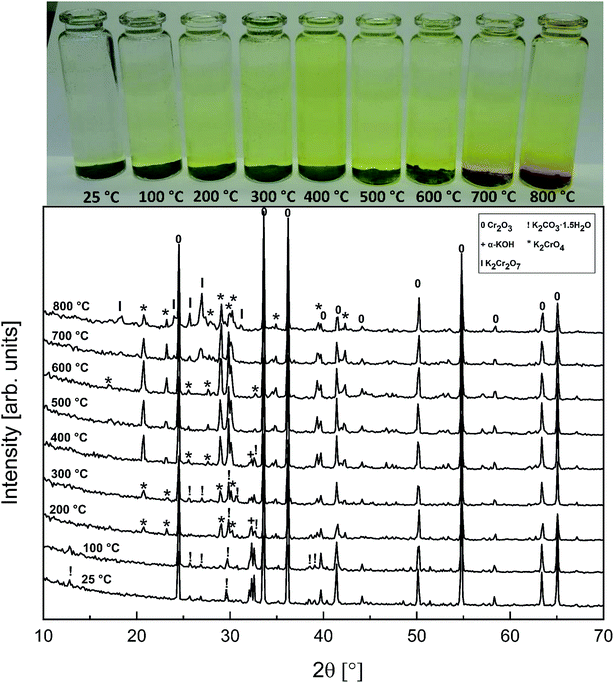 |
| | Fig. 1 XRD patterns and appearance of the water solutions on top of the KOH–Cr2O3 mixtures after furnace exposures. | |
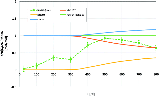 |
| | Fig. 2 Comparison of the experimentally determined amount of [CrO42−] in the filtrates with the thermodynamically predicted amount of the reaction products in the KOH–Cr2O3 system with pure water leaching. | |
3.2 K2CrO4–Cr2O3 system
In order to determine if the K2Cr2O7 formation at higher firing temperatures proceeds directly from the reaction with KOH or via first formation of K2CrO4 and then further reaction with Cr2O3, the K2CrO4–Cr2O3 system was studied with XRD analysis. Results are presented in Fig. 3. From the XRD analysis it is clear that K2CrO4 can react with Cr2O3 and form K2Cr2O7 at exposure temperatures ≥ 500 °C. Therefore, it is suggested that direct reaction of KOH with Cr2O3 forms K2CrO4 and that the formation of K2Cr2O7 requires always the K2CrO4 reaction intermediate to form first.
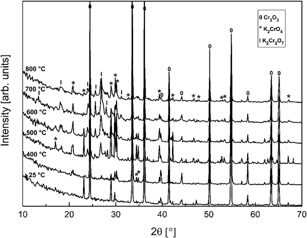 |
| | Fig. 3 XRD patterns for the K2CrO4–Cr2O3 mixtures after furnace exposures. | |
3.3 KCl–Cr2O3 system
Compared to KOH, KCl is substantially less reactive with Cr2O3. As shown in the XRD analysis in Fig. 4, there were no clear signs of reaction with Cr2O3 until the highest firing temperature, 800 °C. At 800 °C, an additional peak was detected at 26.95° (2θ). This peak coincides with the (021) reflection of K2Cr2O7. However, using only one peak in phase identification is not reliable, but based on the analogy with results from the KOH–Cr2O3 and K2CrO4–Cr2O3 systems, K2Cr2O7 was considered to be the most likely reaction product at 800 °C. CrO42− was detected qualitatively and quantitatively also at lower firing temperatures as shown in Fig. 4 and 5. Thermodynamic calculation predicted again the formation of K2Cr2O7 and K2CrO4 as the major products, but now the discrepancy between the thermodynamic prediction and experimental results was higher than with KOH. CrO42− was detected only in samples exposed to firing temperatures ≥ 400 °C and even at 800 °C the CrO42− amount was only ≈16% of the theoretical maximum.
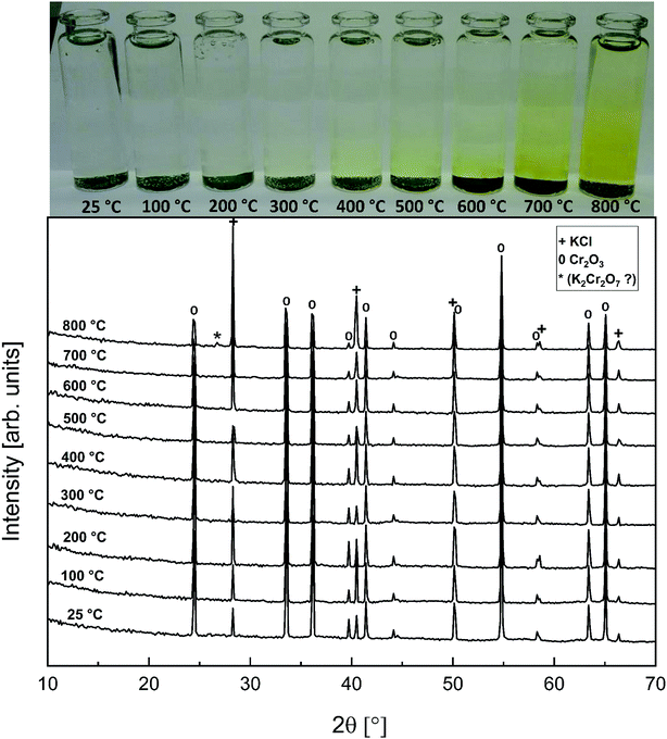 |
| | Fig. 4 XRD patterns and appearance of the water solutions on top of the KCl–Cr2O3 mixtures after furnace exposures. | |
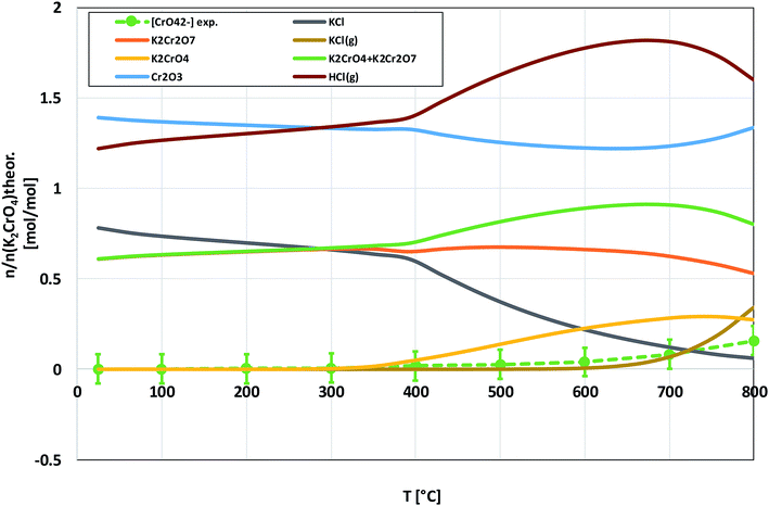 |
| | Fig. 5 Comparison of the experimentally determined amount of [CrO42−] in the filtrates with the thermodynamically predicted amount of the reaction products in the KCl–Cr2O3 system with pure water leaching. | |
3.4 KOH–Fe2O3 system
Fig. 6 shows the XRD analysis of the KOH–Fe2O3 system. Reaction with Fe2O3 started at 200 °C firing temperature, forming KFeO2 as the reaction product. KFeO2 stayed as the major reaction product throughout the temperature range. At 500 °C an additional peak at 27.95° (2θ) was detected that could not be assigned to KFeO2. This peak was assigned to potassium containing magnetite, K1.75Fe1.25O4 that has the maximum intensity powder XRD peak at this position, but with one peak only, the identification remains doubtful. At 800 °C firing temperature, K2Fe4O7 could also be identified as the reaction product in addition to KFeO2. There was no indication of higher oxidation state than +3 reaction products of Fe, such as K2FeO4. This was consistent with the lack of any colour of the water solutions containing the dissolved reaction products shown in Fig. 6. This result reflects the more favourable tendency of Cr to adapt oxidation state +6 compared to Fe. The comparison of the measured water soluble and acid soluble Fe3+ amounts with the thermodynamic prediction are presented in Fig. 7. No water soluble Fe3+ was found, but the amount of acid soluble Fe3+ was very close to the thermodynamically predicted amount of KFeO2. This difference in the filtrates as a function of pH is caused by the fact that either KFeO2 is not soluble in water, or that after initial dissolution of KFeO2, rapid formation of insoluble Fe(OH)3 takes place in the basic solution. The high OH− concentration precipitates the initially dissolved iron and captures it in the filtration residue. In acidic conditions, Fe(OH)3 formation is prevented and KFeO2 was dissolved completely in the 15 min leaching step and the dissolved iron stayed in the solution phase during the filtration step.
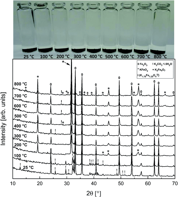 |
| | Fig. 6 XRD patterns and appearance of the water solutions on top of the KOH–Fe2O3 mixtures after furnace exposures. | |
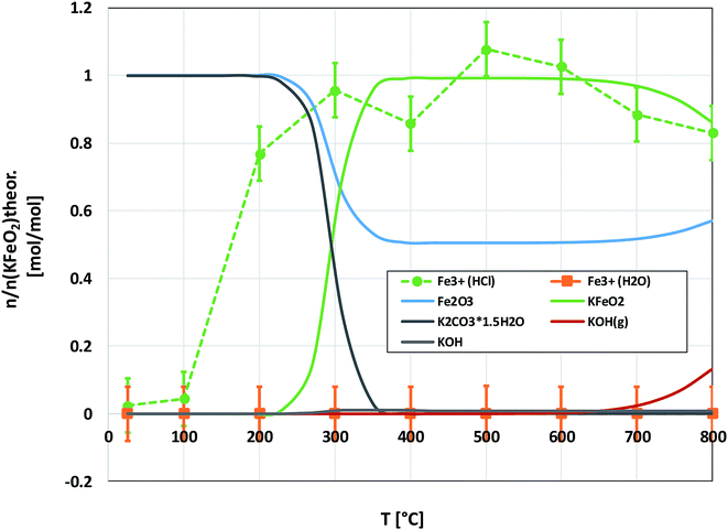 |
| | Fig. 7 Comparison of the experimentally determined amount of [Fe3+] in the filtrates with the thermodynamically predicted amount of the reaction products in the KOH–Fe2O3 system with pure water leaching and leaching in 1 M HCl(aq) solution. | |
3.5 KCl–Fe2O3 system
As with the KCl–Cr2O3 system, KCl turned out to be much less reactive towards Fe2O3 compared to KOH. There was no sign of any reaction in the XRD analysis or in the visual qualitative analysis of the water soluble reaction products as shown in Fig. 8. Similar to the KOH–Fe2O3 case, no water soluble iron was found, but now there was only traces of Fe3+ detected even in the acid soluble filtrate. The results agree with thermodynamic equilibrium calculations, which predicted only slight reaction in the KCl–Fe2O3 system at temperatures > 600 °C to form KFeO2 as shown in Fig. 9.
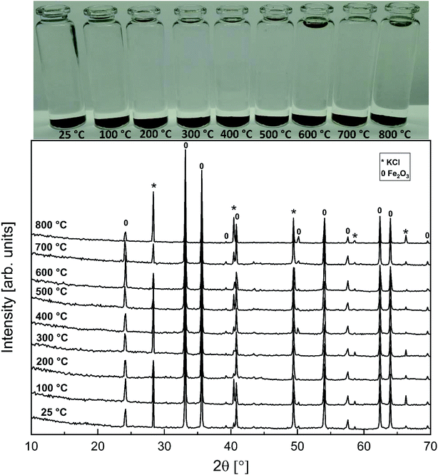 |
| | Fig. 8 XRD patterns and appearance of the water solutions on top of the KCl–Fe2O3 mixtures after furnace exposures. | |
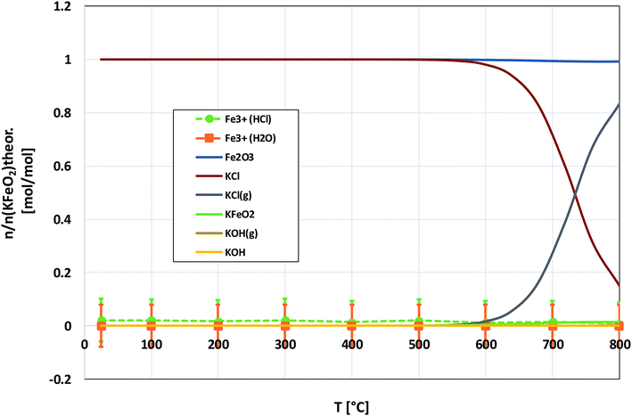 |
| | Fig. 9 Comparison of the experimentally determined amount of [Fe3+] in the filtrates with the thermodynamically predicted amount of the reaction products in the KCl–Fe2O3 system with pure water leaching and leaching in 1 M HCl(aq) solution. | |
4. Discussion
Our results are consistent with the suggestion that the reaction of KCl with Cr2O3 is initiated by K2CrO4 formation as found in the corrosion literature.22,23,43 However, we argue that the suggested overall reaction of KCl with Cr2O3:| |
 | (R1) |
starts with the initiation step:| | |
KCl + H2O(g) ↔ KOH + HCl(g)
| (R2) |
and then the formed KOH can easily react with the protective oxide as shown in the experiments. Previous hypotheses of the mechanisms of steel corrosion under KCl(s) exposures have focused on the effect of Cl2(g) or HCl(g) as the corrosive substances and the effect of KOH has been neglected.44,45 However, combustion environments contain inevitably also H2O(g) in the flue gases and therefore KOH formation should not be neglected. Furthermore, many virgin biomass fuels contain very little Cl, so there is simply not much Cl2(g) or HCl(g) available in the flue gases when combusting these types of fuels. Still KCl layer has been found on the heat exchanger surfaces and previous work has argued that the corroding Cl2(g) or HCl(g) must form from the KCl layer, but the fate of the K when the Cl2(g) or HCl(g) forms from KCl has not been studied in detail. In waste incineration, the situation is different, because the feedstock contains typically large amounts of Cl and therefore the direct gas phase attack by Cl2(g) or HCl(g) may be more relevant. It may be that the chlorine corrosion mechanisms taking place in high chlorine content feedstock combustion cannot be applied to explain the corrosion in virgin biomass combustion.
4.1 Reaction of KOH with Cr2O3
KOH will react readily with Cr2O3, reacting already at 200 °C:| |
 | (R3) |
The formed K2CrO4 can react further to K2Cr2O7 at high temperatures. Direct formation of K2Cr2O7 without the K2CrO4 intermediate is always kinetically hindered:
| |
 | (R4) |
4.2 Reaction of KOH with Fe2O3
KOH will react readily with Fe2O3, reacting already at 200 °C:| | |
2KOH + Fe2O3 → 2KFeO2 + H2O(g) (T ≥ 200 °C)
| (R5) |
Although not experimentally verified in this study, we propose that in analogy to KOH–Cr2O3 case, the formed KFeO2 can react further to K2Fe4O7 at high temperatures. It is suggested that K2Fe4O7 formation without the KFeO2 intermediate is kinetically hindered as the K2Cr2O7 formation in the Cr2O3 case:
| | |
2KFeO2 + Fe2O3 ↔ K2Fe4O7 (T > 700 °C)
| (R6) |
4.3 Reaction of KCl with Cr2O3 and Fe2O3
Based on the results in this study, it is proposed that the reactivity of KCl towards both oxides in H2O(g) containing environment can simply be explained by the thermodynamics of the decomposition reaction R2. Fig. 10 presents the thermodynamic equilibrium of R2 in ambient moist air. It is suggested that HCl(g) does not play a key role in the reaction with the oxides and that the reactive compound is the formed KOH. The reason that we did not detect any reaction between KCl and Fe2O3, but did detect K2CrO4 formation with Cr2O3 at >500 °C can be explained by the higher thermodynamic stability of K2CrO4 compared to KFeO2 as shown in Fig. 11. K2CrO4 is much more stable than KFeO2, therefore it is suggested that the KOH formed in the decomposition of KCl at >500 °C does not form KFeO2 as readily as K2CrO4 and most of the formed KOH is lost in the gas phase by vaporization before reacting with Fe2O3. That is why KFeO2 was not detected in the KCl–Fe2O3 system.
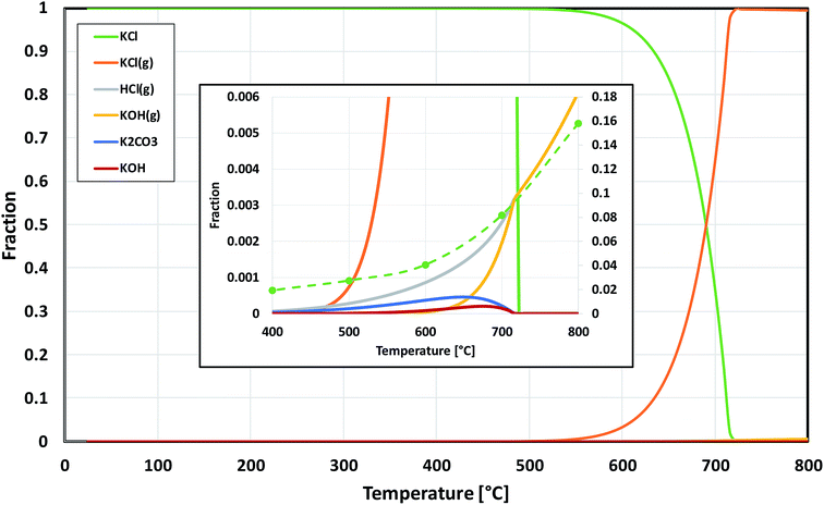 |
| | Fig. 10 Thermodynamic stability of KCl in humid air, calculated with HSC v6.12 software. The inset is a zoomed image from the bottom right corner of the chart. The green dashed line in the inset shows the trend of the experimentally determined amount of potassium reacted to K2CrO4 when KCl and Cr2O3 reacted in the furnace (shown also in Fig. 5). | |
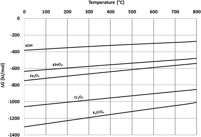 |
| | Fig. 11 Comparison of Gibbs free energies of formation of the reactants and the corrosion products, calculated with HSC v6.12 software. | |
In case of Fe–Cr steel corrosion, once the protective oxide is destroyed by KOH and if the bare metals are exposed to the atmosphere, HCl(g) may take part in the continuation of corrosion:
| |
 | (R7) |
| |
 | (R8) |
| |
 | (R9) |
| |
 | (R10) |
If KCl diffuses through the oxide scale (grain boundary diffusion), the formation of the reactive chlorine species can also take place at the metal-scale interface:
| | |
Cr + 2KCl + 2O2(g) → K2CrO4 + Cl2(g)
| (R11) |
| | |
Cr + 2KCl + 4H2O(g) → K2CrO4 + 2HCl(g) + H2(g)
| (R12) |
| | |
2Fe + 2KCl + 2O2(g) → 2KFeO2 + Cl2(g)
| (R13) |
| | |
2Fe + 2KCl + 2H2O(g) → 2KFeO2 + 2HCl(g) + H2(g)
| (R14) |
The formed chlorine compounds can further attack the metal leading to the active oxidation mechanism by chlorine.46 However, it is somewhat arbitrary to speculate about the corrosion reactions with elemental metals, because these reactive metals in the elemental form will thermodynamically favour reaction with practically any reactant. For example, a chlorine free corrosion mechanism involving only KOH may also be suggested:
| |
 | (R15) |
| |
 | (R16) |
The formed water or the O2(g) diffusing through the oxide scale can further oxidize the underlying metal and form Cr2O3 or Fe2O3 oxides, which are then consumed by KOH according to reactions R3 and R5, and a chlorine free active oxidation mechanism is established. It is argued that KOH diffuses more readily to the metal scale interphase than KCl, because of the lower melting point of KOH (406 °C) compared to KCl (773 °C) and thus higher mobility at typical service temperatures (400–600 °C). Because of the low melting point of KOH, diffusion can also take place in ionic form by K+ and O2− ions diffusing to the metal-scale interphase:
| | |
2KOH ↔ K2O + H2O(g) (in liquid KOH)
| (R17) |
| | |
K2O → 2K+ + O2− (in liquid KOH)
| (R18) |
| |
 | (R19) |
| |
 | (R20) |
The schematic image in Fig. 12 summarizes the proposed corrosion reactions.
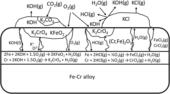 |
| | Fig. 12 Schematic of the proposed corrosion reactions under KOH and KCl containing salt deposit. | |
5. Conclusions
KOH is much more reactive towards Cr2O3 and Fe2O3 than KCl in ambient air environment. Thermodynamic calculations predict the difference in reactivity quite nicely above 400 °C. KOH reacts with both oxides at temperatures higher than 200 °C while KCl reacts with Cr2O3 at temperatures > 400 °C, but no reaction with Fe2O3 was detected in the temperature range from room temperature to 800 °C. Both KOH and KCl form K2CrO4 as the reaction product when reacting with Cr2O3. K2CrO4 can further react with Cr2O3 and form K2Cr2O7 at temperatures > 400 °C. K2CrO4 and K2Cr2O7 reaction products can be easily leached from the mixture with water at room temperature. KOH forms KFeO2 as the reaction product when reacting with Fe2O3. KFeO2 cannot be leached with pure water, but requires an acidic media. In 1 M HCl solution, KFeO2 can be easily leached at room temperature. The reactivity of KCl towards the protective oxides of Fe–Cr steels in water containing high temperature environments can be explained by its decomposition to KOH and HCl(g) and the subsequent reaction of the formed KOH with the protective oxide. These results are very valuable for the development of materials for boilers, gasifiers, furnaces and gas turbines utilizing biomass derived fuels as their energy source.
Conflicts of interest
There are no conflicts of interest to declare.
Acknowledgements
The financial support from the Academy of Finland Strategic Research Council (SRC) and Finnish Environment Institute (SYKE) through the CloseLoop project is gratefully appreciated.
References
- IEA statistics, CO2 Emissions from Fuel Combustion 2017 Highlights, 1 October 2017 Search PubMed.
- Y. Niu, H. Tan and S. Hui, Ash-related issues during biomass combustion: alkali-induced slagging, silicate melt-induced slagging (ash fusion), agglomeration, corrosion, ash utilization, and related countermeasures, Prog. Energy Combust. Sci., 2016, 52, 1–61 CrossRef.
- H. P. Nielsen, F. J. Frandsen, K. Dam-Johansena and L. L. Baxter, The implications of chlorine-associated corrosion on the operation of biomass-fired boilers, Prog. Energy Combust. Sci., 2000, 26, 283–298 CrossRef CAS.
- R. A. Antunes and M. C. L. Oliveira, Corrosion in biomass combustion: a materials selection analysis and its interaction with corrosion mechanisms and mitigation strategies, Corros. Sci., 2013, 76, 6–26 CrossRef CAS.
- I. Obernberger, F. Biedermann, W. Widmann and R. Riedl, Concentrations of inorganic elements in biomass fuels and recovery in the different ash fractions, Biomass Bioenergy, 1997, 12, 211–224 CrossRef CAS.
- L. L. Baxtera, T. R. Miles, T. R. Miles Jr, B. M. Jenkins, T. Milne, D. Dayton, R. W. Bryerse and L. L. Oden, The behavior of inorganic material in biomass-fired power boilers: field and laboratory experiences, Fuel Process. Technol., 1998, 54, 47–78 CrossRef.
- C. Chen, Z. Luo, C. Yu, T. Wang and H. Zhang, Transformation behavior of potassium during pyrolysis of biomass, RSC Adv., 2017, 7, 31319–31325 RSC.
- D. C. Dayton, R. J. French and T. A. Milne, Direct Observation of Alkali Vapor Release during Biomass Combustion and Gasification. 1. Application of Molecular Beam/Mass Spectrometry to Switchgrass Combustion, Energy Fuels, 1995, 9, 855–865 CrossRef CAS.
- T. Sorvajärvi, N. DeMartini, J. Rossi and J. Toivonen, In Situ Measurement Technique for Simultaneous Detection of K, KCl, and KOH Vapors Released during Combustion of Solid Biomass Fuel in a Single Particle Reactor, Appl. Spectrosc., 2014, 68, 179–184 CrossRef PubMed.
- P. E. Mason, L. I. Darvell, J. M. Jones and A. Williams, Observations on the release of gas-phase potassium during the combustion of single particles of biomass, Fuel, 2016, 182, 110–117 CrossRef CAS.
- Y. Niu, Z. Wang, Y. Zhu, X. Zhang, H. Tan and S. Hui, Experimental evaluation of additives and K2O–SiO2–Al2O3 diagrams on high-temperature silicate melt-induced slagging during biomass combustion, Fuel, 2016, 179, 52–59 CrossRef CAS.
- B. Anicic, W. Lin, K. Dam-Johansen and H. Wu, Agglomeration mechanism in biomass fluidized bed combustion – reaction between potassium carbonate and silica sand, Fuel Process. Technol., 2018, 173, 182–190 CrossRef CAS.
- M. Hupa, Ash-Related Issues in Fluidized-Bed Combustion of Biomasses: Recent Research Highlights, Energy Fuels, 2012, 26, 4–14 CrossRef CAS.
- L. Hindiyarti, F. Frandsen, H. Livbjerg, P. Glarborg and P. Marshall, An exploratory study of alkali sulfate aerosol formation during biomass combustion, Fuel, 2008, 87, 1591–1600 CrossRef CAS.
- S. Jiménez and J. Ballester, Formation and Emission of Submicron Particles in Pulverized Olive Residue (Orujillo) Combustion, Aerosol Sci. Technol., 2004, 38, 707–723 CrossRef.
- L. A. Hansen, H. P. Nielsen, F. J. Frandsen, K. Dam-Johansen, S. Hørlyck and A. Karlsson, Influence of deposit formation on corrosion at a straw-fired boiler, Fuel Process. Technol., 2000, 64, 189–209 CrossRef CAS.
- H. Wu, M. S. Bashir, P. A. Jensen, B. Sander and P. Glarborg, Impact of coal fly ash addition on ash transformation and deposition in a full-scale wood suspension-firing boiler, Fuel, 2013, 113, 632–643 CrossRef CAS.
- W. Weng, S. Chen, H. Wu, P. Glarborg and Z. Li, Optical Investigation of Gas-phase KCl/KOH Sulfation in Post Flame Conditions, Fuel, 2018, 224, 461–468 CrossRef CAS.
- B. Li, Z. Sun, Z. Li, M. Aldén, J. G. Jakobsen, S. Hansen and P. Glarborg, Post-flame gas-phase sulfation of potassium chloride, Combust. Flame, 2013, 160, 959–969 CrossRef CAS.
- K. Schofield, The chemical nature of combustion deposition and corrosion: the case of alkali chlorides, Combust. Flame, 2012, 159, 1987–1996 CrossRef CAS.
- M. Broström, S. Enestam, R. Backman and K. Mäkelä, Condensation in the KCl–NaCl system, Fuel Process. Technol., 2013, 105, 142–148 CrossRef.
- S. Karlsson, J. Pettersson, L.-G. Johansson and J.-E. Svensson, Alkali Induced High Temperature Corrosion of Stainless Steel: The Influence of NaCl, KCl and CaCl2, Oxid. Met., 2012, 78, 83–102 CrossRef CAS.
- J. Pettersson, H. Asteman, J.-E. Svensson and L.-G. Johansson, KCl Induced Corrosion of a 304-type Austenitic Stainless Steel at 600°C; The Role of Potassium, Oxid. Met., 2005, 64, 23–41 CrossRef CAS.
- Y. S. Lia, M. Spiegel and S. Shimada, Effect of Al/Si addition on KCl induced corrosion of 9% Cr steel, Mater. Lett., 2004, 58, 3787–3791 CrossRef.
- H. T. Ma, C. H. Zhou and L. Wang, High temperature corrosion of pure Fe, Cr and Fe–Cr binary alloys in O2 containing trace KCl vapour at 750 °C, Corros. Sci., 2009, 51, 1861–1867 CrossRef CAS.
- S. Kiamehr, K. V. Dahl, M. Montgomery and M. A. J. Somers, KCl-induced high temperature corrosion of selected commercial alloys, Mater. Corros., 2015, 66, 1414–1429 CrossRef CAS.
- T. Ishitsuka and K. Nose, Solubility study on protective oxide films in molten chlorides created by refuse incineration environment, Mater. Corros., 2000, 51, 177–181 CrossRef CAS.
- K. Segerdahl, J. Pettersson, J. E. Svensson and L. G. Johansson, Is KCl(g) Corrosive at Temperatures Above its Dew Point? Influence of KCl(g) on Initial Stages of the High Temperature Corrosion of 11% Cr Steel at 600°C, Mater. Sci. Forum, 2004, 461–464, 109–116 CAS.
- J. Lehmusto, D. Lindberg, P. Yrjas, B.-J. Skrifvars and M. Hupa, Thermogravimetric studies of high temperature reactions between potassium salts and chromium, Corros. Sci., 2012, 59, 55–62 CrossRef CAS.
- J. Pettersson, N. Folkeson, L.-G. Johansson and J.-E. Svensson, The Effects of KCl, K2SO4 and K2CO3 on the High Temperature Corrosion of a 304-Type Austenitic Stainless Steel, Oxid. Met., 2011, 76, 93–109 CrossRef CAS.
- G. Y. Lai, High-Temperature Corrosion and Materials Applications, ASM International, Ohio, 2007 Search PubMed.
- G. P. Smith, Corrosion of materials in fused hydroxides, Oak Ridge National Laboratory Report, Tennessee, 1956 Search PubMed.
- Tz. Tzvetkoff and J. Kolchakov, Mechanism of growth, composition and structure of oxide films formed on ferrous alloys in molten salt electrolytes—a review, Mater. Chem. Phys., 2004, 87, 201–211 CrossRef CAS.
- T. Blomberg, A thermodynamic study of the gaseous potassium chemistry in the convection sections of biomass fired boilers, Mater. Corros., 2011, 57, 170–175 CrossRef.
- T. Blomberg, Correlation of the corrosion rates of steels in a straw fired boiler with the thermodynamically predicted trend of KOH (g) in the flue gases, Biomass Bioenergy, 2012, 39, 489–493 CrossRef CAS.
- S. Parirenyatwa, L. Escudero-Castejon, S. Sanchez-Segado, Y. Hara and A. Jha, Comparative study of alkali roasting and leaching of chromite ores and titaniferous minerals, Hydrometallurgy, 2016, 165, 213–226 CrossRef CAS.
- N. Li, E. Vainio, L. Hupa, M. Hupa and E. C. Zabetta, High-Temperature Corrosion of Refractory Materials in Biomass and Waste Combustion: Method Development and Tests with Alumina Refractory Exposed to a K2CO3–KCl Mixture, Energy Fuels, 2017, 31, 10046–10054 CrossRef CAS.
- Z. Zhou, Y. Bo, Y. Zhang, Z. Huang, L. Chen, L. Ge, J. Zhou and K. Cen, Interactions of high-chromia refractory materials with infiltrating coal slag in the oxidizing atmosphere of a cyclone furnace, Ceram. Int., 2014, 40, 3829–3839 CrossRef CAS.
- M. Szabó, J. Kalmár, T. Ditrói, G. Bellér, G. Lente, N. Simic and I. Fábián, Equilibria and kinetics of chromium(VI) speciation in aqueous solution – a comprehensive study from pH 2 to 11, Inorg. Chim. Acta, 2018, 472, 295–301 CrossRef.
- C. C. A. Loures, M. A. K. Alcântara, H. J. I. Filho, A. C. S. C. Teixeira, F. T. Silva, T. C. B. Paiva and G. R. L. Samanamud, Advanced Oxidative Degradation Processes: Fundamentals and Applications, Int. Rev. Chem. Eng., 2013, 5, 102–120 Search PubMed.
- A. Roine, et al., Outokumpu HSC Chemistry for Windows, Chemical Reaction and Equilibrium Software 6.12, 2007 Search PubMed.
- F. T. Mackenzie and J. A. Mackenzie, Our changing planet, Prentice-Hall, Upper Saddle River, New Jersey, 1995 Search PubMed.
- T. Jonsson, J. Froitzheim, J. Pettersson, J.-E. Svensson, L.-G. Johansson and M. Halvarsson, The Influence of KCl on the Corrosion of an Austenitic Stainless Steel (304L) in Oxidizing Humid Conditions at 600 °C: A Microstructural Study, Oxid. Met., 2009, 72, 213–239 CrossRef CAS.
- M. Spiegel, A. Zahs and H. J. Grabke, Fundamental aspects of chlorine induced corrosion in power plants, Mater. High Temp., 2003, 20, 153–159 CrossRef CAS.
- M. Montgomery, A. Karlsson and O. H. Larsen, Field test corrosion experiments in Denmark with biomass fuels. Part 1: Straw-firing, Mater. Corros., 2002, 53, 121–131 CrossRef CAS.
- H. J. Grabke, E. Reese and M. Spiegel, The effects of chlorides, hydrogen chloride, and sulfur dioxide in the oxidation of steels below deposits, Corros. Sci., 1995, 37, 1023–1043 CrossRef CAS.
Footnotes |
| † Electronic supplementary information (ESI) available. See DOI: 10.1039/c9ra00582j |
| ‡ The raw/processed data required to reproduce these findings are partly included in the ESI section of the manuscript. Additional raw data is available from the authors upon request. |
|
| This journal is © The Royal Society of Chemistry 2019 |
Click here to see how this site uses Cookies. View our privacy policy here.  Open Access Article
 *,
Tripurari Tripathi and
Maarit Karppinen
 , starting with the initiation step: KCl + H2O(g) ⇒ KOH + HCl(g) and then the formed KOH reacts with Cr2O3 to form K2CrO4. This explains the initial breakdown of the protective Cr2O3 under KCl salt in water containing high temperature atmospheres. The result is essential for the development of new alloys for biomass fired combustors.
![[thin space (1/6-em)]](https://www.rsc.org/images/entities/char_2009.gif) :
:![[thin space (1/6-em)]](https://www.rsc.org/images/entities/char_2009.gif) 10 or 1
10 or 1![[thin space (1/6-em)]](https://www.rsc.org/images/entities/char_2009.gif) :
:![[thin space (1/6-em)]](https://www.rsc.org/images/entities/char_2009.gif) 20 dilution ratios, which ever was suitable to bring the absorbance value in between the standards. Molar ratios reacted to K2CrO4 and K2Cr2O7 were calculated as follows:
20 dilution ratios, which ever was suitable to bring the absorbance value in between the standards. Molar ratios reacted to K2CrO4 and K2Cr2O7 were calculated as follows:

![[thin space (1/6-em)]](https://www.rsc.org/images/entities/char_2009.gif) :
:![[thin space (1/6-em)]](https://www.rsc.org/images/entities/char_2009.gif) 1 ratio of sample with a solution to 1 mol l−1 HCl (1
1 ratio of sample with a solution to 1 mol l−1 HCl (1![[thin space (1/6-em)]](https://www.rsc.org/images/entities/char_2009.gif) :
:![[thin space (1/6-em)]](https://www.rsc.org/images/entities/char_2009.gif) 2 dilution). This pH stabilized solution was then used to fill the quartz cuvette in the UV/VIS absorption measurements. The added Cl-ion can also form complex ions with Fe in the form Fe(H2O)6−x(Cl)x3−x. Concentration standards were prepared by dissolving known amounts of FeCl3·6H2O powder to ion exchanged water and diluting (ESI†). The pH of the standards were buffered to 1 with 1 mol l−1 HCl before measurement as with the samples. Then the absorbance of the standards were measured and linear concentration–absorbance curves were established. Then the absorbance of the sample filtrates were measured and the concentrations were determined using the standard curves. Molar ratios reacted to KFeO2 were calculated as follows:
2 dilution). This pH stabilized solution was then used to fill the quartz cuvette in the UV/VIS absorption measurements. The added Cl-ion can also form complex ions with Fe in the form Fe(H2O)6−x(Cl)x3−x. Concentration standards were prepared by dissolving known amounts of FeCl3·6H2O powder to ion exchanged water and diluting (ESI†). The pH of the standards were buffered to 1 with 1 mol l−1 HCl before measurement as with the samples. Then the absorbance of the standards were measured and linear concentration–absorbance curves were established. Then the absorbance of the sample filtrates were measured and the concentrations were determined using the standard curves. Molar ratios reacted to KFeO2 were calculated as follows:

![[thin space (1/6-em)]](https://www.rsc.org/images/entities/char_2009.gif) :
:![[thin space (1/6-em)]](https://www.rsc.org/images/entities/char_2009.gif) 2, 1
2, 1![[thin space (1/6-em)]](https://www.rsc.org/images/entities/char_2009.gif) :
:![[thin space (1/6-em)]](https://www.rsc.org/images/entities/char_2009.gif) 50 or 1
50 or 1![[thin space (1/6-em)]](https://www.rsc.org/images/entities/char_2009.gif) :
:![[thin space (1/6-em)]](https://www.rsc.org/images/entities/char_2009.gif) 100 dilution ratios, which ever was suitable to bring the absorbance value in between the standards. In the 1
100 dilution ratios, which ever was suitable to bring the absorbance value in between the standards. In the 1![[thin space (1/6-em)]](https://www.rsc.org/images/entities/char_2009.gif) :
:![[thin space (1/6-em)]](https://www.rsc.org/images/entities/char_2009.gif) 50 and 1
50 and 1![[thin space (1/6-em)]](https://www.rsc.org/images/entities/char_2009.gif) :
:![[thin space (1/6-em)]](https://www.rsc.org/images/entities/char_2009.gif) 100 dilution cases, the dilution was done by adding 1 ml of sample, then 5 ml of 1 mol l−1 HCl, and then filling the volumetric flask with pure H2O.
100 dilution cases, the dilution was done by adding 1 ml of sample, then 5 ml of 1 mol l−1 HCl, and then filling the volumetric flask with pure H2O.


