 Open Access Article
The conversion of α-pinene to cis-pinane using a nickel catalyst supported on a discarded fluid catalytic cracking catalyst with an ionic liquid layer†
Shunyou Hu a,
Linlin Wang
 *ab,
Xiaopeng Chenab,
Xiaojie Weiab,
Zhangfa Tong
 ab and
Lijiang Yina
aSchool of Chemistry and Chemical Engineering, Guangxi University, Nanning 530004, P. R. China. E-mail: wanglinlin1971@sina.com; Fax: +86-771-323-3718; Tel: +86-771-3272702
bGuangxi Key Laboratory of Petrochemical Resource Processing and Process Intensification Technology, Nanning 530004, P. R. China
First published on 18th February 2019
Abstract
The concept of a solid catalyst coated with a thin ionic liquid layer (SCILL) was applied to the stereoselective hydrogenation of α-pinene. Nickel, a non-noble metal, was supported on a discarded fluid catalytic cracking catalyst (DF3C) and then modified with different loadings of the ionic liquid 1-ethanol-3-methylimidazolium tetrafluoroborate ([C2OHmim][BF4]). The resulting catalysts showed a range of conversions and selectivities for the hydrogenation of α-pinene. The SCILL catalysts afforded cis-pinane with high selectivity and their activity depended on the ionic liquid loading. For an ionic liquid loading of 10 wt%, although the catalytic activity was suppressed, the selectivity and conversion could reach above 98% and 99%, respectively. In addition, the catalyst remained stable after 13 runs and the activity was almost unchanged with the conversion maintained at approximately 99%. Thus, the ionic liquid layer not only improved the selectivity for cis-pinane but also protected the active site of the catalyst and prolonged the service lifetime of the catalyst. The SCILL catalytic system provides an example of an ionic liquid catalytic system which eliminates organic solvents from the catalytic process.
Introduction
As a natural, green, and renewable product, α-pinene has drawn great interest for applications in the pharmaceutical, bioenergy, fine chemistry, and flavouring industries.1 There are two kinds of hydrogenation products of α-pinene, namely, cis-pinane and trans-pinane, and among these two products, cis-pinane is more desirable since the content of cis-pinane in raw materials should be greater than 90% to reduce by-products and simplify post-treatments. There is a need to design and identify more effective catalysts for the selective hydrogenation of α-pinene to improve the yield of cis-pinane. To date, various studies have focused on hydrogenation of α-pinene, including a report by Hou et al. on Ru nanoparticles in aqueous micellar microreactors as catalysts with a high selectivity for cis-pinane under mild conditions.2 Milewska et al. studied biphasic hydrogenation of α-pinene over Pd/C under a high pressure of carbon dioxide.3 Deliy et al. reported that hydrogenation and isomerization of pinenes occur simultaneously on Ru/C, Rh/C, Pt/C, and Ir/C catalysts.4 Selka et al. achieved excellent catalytic activity and selectivity based on their studies into hydrogenation of α-pinene over Pd-based catalysts on different supports; however, the reusability of these catalysts was poor.1 Simakova et al. investigated the hydrogenation of α-pinene over 4 wt% palladium on carbon (Pd/C) as a catalyst with n-octane as a solvent.5 Tanielyan et al. used ethanol as solvent in their studies of pinene hydrogenation over anchored Wilkinson catalyst.6 However, noble metal catalysts and organic solvents are expensive, environmentally unfriendly, and the lack of reusability of these catalysts poses major challenges.Discarded fluid catalytic cracking catalyst (DF3C) is a kind of industrial waste product from petroleum refining processes. DF3C contains heavy metals such as iron, nickel, and vanadium, which were contained in the heavy oil subjected to the reactions. A large amount of DF3C is produced every year, the majority of which is sent to landfill, risking environmental pollution, from heavy metals seeping into groundwater.7 Recently, attention has been paid to recovering DF3C, and it has been applied as a catalyst for cracking of waste plastics,8 a source of heavy metals,7 and rare earth elements.11,12 DF3C is mainly composed of Al2O3, SiO2, and residual nickel, with a rich pore structure and large specific surface area; hence, DF3C might act as an effective active metal carrier.
Ionic liquid is a new molten salt system that consists of cation and anion that exist in liquid form at room temperature, which can be designed according to specific requirements. Ionic liquids have many properties different from conventional organic solvent, such as thermal stability,9 electrochemical stability,10,11 and adjustable electric fields, which were the powerful supports for using ionic liquids as catalysts modifiers to achieve excellent catalytic performance and longer service lives. These features enable ionic liquid to regulate the activity and selectivity of catalysts. Owing to its unique properties, the ionic liquid is used in chemical research as a solvent for various types of reactions,12–16 extractant in separation/purification,17–20 and has applications in the field of electrochemistry.21–23 Zhao et al. have reported the synthesis of CoSx nanosheets from ionic liquid and applied it for the oxygen evolution reaction.24 Zhao et al. have developed liquid-exfoliation method to produce stable and high-concentration dispersions of mono- to few-layer black phosphorus nanosheets using ionic liquid.25 Li et al. has used the ionic liquid to assist synthesis of Au–Pd bimetallic particles with enhanced electrocatalytic activity.26 And Brown et al. have studied the asymmetric hydrogenation and catalyst recycling using ionic liquid and supercritical carbon dioxide.27 When an ionic liquid is used as a reaction medium, it can alter the electronic environment of catalyst active sites; thus, ionic liquids can tune the catalytic effectiveness of non-precious metal catalysts to be as good as, or even better than those of noble metal catalysts, particularly in terms of catalyst selectivity. Ionic liquids can act as selective controllers for organic transformations, such as the selective hydrogenation of nitriles or alkynes.28 The inherent high viscosity of ionic liquids causes mass transfer resistance, which severely inhibits the reaction rate. Additionally, ionic liquids are not generally mass-produced but rather used on a laboratory scale, which limits the use of ionic liquids as reaction media. To address the above problems, the concept of a solid catalyst coated with a thin ionic liquid layer (SCILL) has been proposed and applied in various catalytic reactions.29 Notably, selective hydrogenation reactions show markedly enhanced selectivity compared with those of conventional solid catalysts. Schwab et al. reported a highly cis-selective and lead-free hydrogenation of 2-hexyne by a supported Pd catalyst with an ionic liquid layer.30 Hou et al. reported on Pd/SiO2 coated with [DMIM][MeHPO3] for the selective hydrogenation of acetylene.31 The excellent selectivity of SCILL-based catalysts can be mainly attributed to the filter effect, which regulates the effective concentration of substances at the active sites of catalysts together with the ligand effects of the ionic liquid, which change the electron density distribution of active sites and affect interactions of reactants and intermediates with active metals.32
In this work, a SCILL catalyst for α-pinene hydrogenation with nickel, a non-noble metal, was developed in combination with the industrial waste carrier DF3C and the ionic liquid 1-ethanol-3-methylimidazolium tetrafluoroborate ([C2OHmim][BF4]), as shown in Scheme 1. The effects of temperature, pressure, ionic liquid loading on the hydrogenation of α-pinene were explored. The lifetime of the catalyst with or without ionic liquid, under the same reaction conditions was also examined. The textural and morphological properties of the catalysts were investigated through X-ray diffraction (XRD), scanning electron microscope (SEM) imaging, Fourier transform infrared (FT-IR), N2 adsorption–desorption, and X-ray photoelectron spectroscopy (XPS).
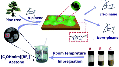 | ||
| Scheme 1 The preparation procedure and application of SCILL catalyst. Ni/DF3C (A), NiO/DF3C (B), DF3C (C). | ||
Experimental
Materials
Nickel(II) nitrate hexahydrate (Ni(NO3)2·6H2O, Shanghai Xingao Chemical Reagent Co., Ltd., 99.0%), acetone (CH3COCH3, KESHI, 99.9%), α-pinene (C10H16, Aladdin, 98%), N-methylimidazole (C4H6N2, Aladdin, 99.0%), 2-chloroethanol (C2H5ClO, Xiya Chemical Co., Ltd., 99.0%), sodium fluoroborate (NaBF4, Macklin, 99.0%), and dichloromethane (CH2Cl2, Beijing Chemical Works Co., Ltd., 99.0%). DF3C was provided by Guangxi Tiandong Petrochemical Co., Ltd. All materials were commercially available and used without further purification except for the DF3C.Synthesis of ionic liquid
The ionic liquid 1-ethanol-3-methylimidazolium tetrafluoroborate [C2OHmim][BF4] was synthesized according to a literature procedure.33 First, 1-methylimidazole (50.00 g, 0.60 mol) was placed in a round-bottom flask (250 mL) with a magnetic stirrer and spherical condenser. Then 2-chloroethanol (60.38 g, 0.75 mol) was added slowly with a constant pressure funnel at a steady rate (two drops a second) for 72 h under argon atmosphere at 85 °C with oil bath heating. After two stable phases formed, the upper liquid phase (containing the reactants for the reaction) was poured off and the bottom phase was washed with ethyl acetate (6 × 30 mL). The combined washings were dried by rotary evaporation over 48 h at 90 °C in a high vacuum environment. The dried product (50 g, 0.3 mol), acetone (150 mL), and NaBF4 (38 g, 0.34 mol) were added to a single-neck round bottom flask (250 mL) and stirred at room temperature for 72 h. The liquid phase product was separated by vacuum filtration and washed with acetone (4 × 30 mL) and then transferred to the vacuum rotary evaporator to remove the solvent and obtain the pure ionic liquid, [C2OHmim][BF4].Preparation of IL-Ni/DF3C
First, DF3C was placed in a muffle furnace and calcined at a high temperature of 500 °C for 5 h to burn off carbon deposits on its surface. Then the DF3C was impregnated by incipient wetness with a nickel nitrate solution (10 wt% Ni loading) and polyvinylpyrrolidone (1.5 wt%). The mixture was left overnight at room temperature and then dried at 110 °C for 4 h under vacuum. The dried product was again placed in a muffle furnace and calcined at 550 °C for 4 h to obtain the precursor for the catalyst, NiO/DF3C. Finally, the precursor was reduced under flow of H2 under temperature programmed to obtain Ni/DF3C. The IL-Ni/DF3C was prepared by a conventional impregnation method. The acetone solution of [C2OHmim][BF4] was added dropwise to the Ni/DF3C, mixed fully, and then transferred to a vacuum drying oven at 60 °C for 3 h. The acetone slowly evaporated from the slurry; however, the ionic liquid remained on the inner surface of the Ni/DF3C as a result of its characteristically high viscosity and low volatility. The initial ionic liquid loading ranged from 0 wt% to 20 wt%. The catalysts are denoted as X-Ni/DF3C, where X refers to the ionic liquid loading.Characterization
XRD patterns were obtained with a Shimadzu XRD-600 advance powder diffractometer operated at 45 kV and 40 mA, using Cu-Kα radiation. The samples were scanned over Bragg angles in the range from 10–80° at a scan rate of 10° min−1. XPS was measured with an ESCALAB 250XI+ spectrometer, and the binding energy scales for samples were referenced by calibration to the C 1s binding energy of adventitious carbon at 284.8 eV, with peaks fitted by Gaussian–Lorentzian curves with the use of XPSPEAK. SEM imaging was performed on a Zeiss Sigma HD with an SE detector. The specific surface areas, average pore width, and total pore volume were calculated with the Brunauer–Emmett–Teller (BET) equation and Barrett–Joyner–Halenda (BJH) methods with the use of a Micromeritics 3Flex instrument. FTIR measurements were performed in a Nicolet IS 10 FTIR spectrometer at a resolution of 4 cm−1 with an average of 20 background scans and 50 sample scans from 4000 to 400 cm−1.Catalyst performance testing
Catalytic hydrogenation experiments of α-pinene were performed in a batch reactor comprising a 100 mL stainless steel autoclave (Shanghai Huotong Experimental Instrument Co., Ltd., China) with a maximum pressure of 25 MPa. A schematic of the experimental setup is depicted in Scheme S1.† Approximately 60 mL of α-pinene and 5 g of the catalyst were introduced into the autoclave. The air in the reactor was purged with a vacuum pump for 20 minutes. Then, hydrogen from the cylinder was introduced into the reaction still at a pressure of 5 MPa and maintained for 20 minutes to ensure that the reactor did not leak. Then the gas in the reactor was discharged to the atmosphere through the discharge valve, and the vessel was recharged with hydrogen at 5 MPa. This operation was cycled 4 times to ensure that the reactor contained no residual air. The reactor was heated to a target temperature of 100 °C at a relatively low hydrogen pressure (0.05 MPa) and rotation speed (50 rpm stirring rate) to avoid excessive reaction during the heating process. The stirring speed and hydrogen pressure were adjusted to the desired value (5 MPa). During the reaction, the hydrogen pressure in the reactor was maintained at a constant value by controlling the inlet valve. After the reaction, cooling water was flowed through the heat exchange coil in the reaction vessel bring the temperature of the reactor to room temperature. The product was then separated from the mixture by vacuum filtration and samples were qualitatively analyzed by a gas chromatography-mass spectrometer (GC-MS) on an Agilent 6890/5973 GC-MS equipped with a HP-5MS capillary column (30 m × 0.25 mm i.d. × 0.25 μm film thickness). Quantitative analyses were carried out using GC on an HP7820 GC equipped with a flame ionization detector (FID) and an HP-5 capillary column (30 m × 0.25 mm i.d. × 0.25 μm film thickness). The temperature of the injector and the detector were 250 °C. The oven temperature was programmed as follows: from 50 °C to 65 °C at a rate of 1 °C min−1, and finally holding at 150 °C for 5 min. The qualitative analysis was conducted on the basis of the holding time of the peak. The content of the reactants and products was directly obtained by the GC chemstation system, according to the area of each chromatograph peak. Conversion of α-pinene (Xα-pinene) and selectivity to cis-pinane (Scis-pinane) were calculated by eqn (1) and (2):
 | (1) |
 | (2) |
Results and discussion
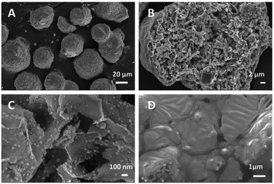
The main goal of the present work was to achieve maximum selectivity to cis-pinane in the hydrogenation of α-pinene. In the present work on catalyst screening for α-pinene, Ni supported on DF3C coated with ionic liquid layer showed about 98% selectivity to cis-pinane by suppressing the by-product formation. In continuation, detail catalyst characterization for understanding the observed highest selectivity to cis-pinane is discussed below.Nitrogen adsorption–desorption isotherms of the catalysts were measured as shown in Table 1. The specific surface area of the DF3C without any pretreatment was 124.06 m2 g−1, however, after calcination, the specific surface area of the DF3C increased to 225.74 m2 g−1, and the average pore width decreased from 9.23 nm for DF3C to 5.28 nm and the total pore volume increased from 0.15 to 0.16 cm3 g−1. These changes are likely caused by the layer of carbon on the surface of DF3C, which also contributed to catalyst deactivation. A relatively large specific surface area and specific pore volume were confirmed in the treated DF3C by SEM imaging (Fig. 1). Comparing the catalysts with different ionic liquid loadings showed that the specific surface area of the catalyst decreased rapidly as the ionic liquid loading increased. Comparing the catalysts before and after used showed that the specific surface area of the catalysts decreased after used, which is attributed to deposition of reactants on the catalyst surface during the reaction. Furthermore, the specific surface area for 0.10-IL-Ni/DF3C after 20 runs was greater than that of 0.10-IL-Ni/DF3C (fresh), which might be caused by the leaching ionic liquid as reported by early literature.34
| Samples | Surface area (m2 g−1) | Average pore size (nm) | Total pore volume (cm3 g−1) |
|---|---|---|---|
| DF3C | 124.06 | 9.23 | 0.15 |
| DF3C after calcinations | 225.74 | 5.28 | 0.16 |
| Ni/DF3C | 197.83 | 6.79 | 0.16 |
| 0.05-IL-Ni/DF3C | 153.72 | 9.06 | 0.15 |
| 0.10-IL-Ni/DF3C | 99.38 | 10.15 | 0.14 |
| 0.10-IL-Ni/DF3C (used) | 96.05 | 10.69 | 0.14 |
| 0.10-IL-Ni/DF3C (20 runs) | 149.74 | 9.33 | 0.15 |
| 0.15-IL-Ni/DF3C | 37.95 | 14.87 | 0.07 |
| 0.20-IL-Ni/DF3C | 8.26 | 28.39 | 0.03 |
The morphologies and microstructures of the prepared samples were characterized by SEM. The DF3C was composed of spherical particles with a rugged surface and a particle size of approximately 50 μm (Fig. 1A). Notably, the rich pore structure of DF3C and its large specific surface area (Fig. 1B), are suitable characteristics for a catalyst support. Comparing the pictures of the Ni/DF3C coated with or without ionic liquid, the ionic liquid layer caused the inner surface of the catalyst to appear smooth (Fig. 1D), unlike the rough surfaces of the DF3C support. This viscous appearance in the SEM images is attributed to the surfaces of the nickel crystal being covered by a layer of ionic liquid. SEM-EDX was used to analyze the dispersion of the ionic liquid and the active metal nickel on the DF3C (Fig. S1†). Here, nitrogen and fluorine could be representative of the distribution of the ionic liquid, and the results showed that the ionic liquid and active metal nickel were relatively evenly distributed over the surface of the catalyst.
The X-ray diffraction (XRD) pattern of the catalysts is shown in Fig. 2. The patterns featured 13 peaks, which corresponded to zeolite Y, Al2O3, and ZSM-5, respectively (Fig. 2a). The diffraction peaks for the DF3C sample became more intense after calcination (Fig. 2b) since the carbon covering the surface of the catalyst is burned off. For DF3C loaded nickel (Fig. 2c), in addition to the previously mentioned diffraction peaks, three characteristic peaks at 2θ = 44.5°, 51.8°, and 76.3° corresponded to the (111), (200), and (220) planes of Ni, respectively. Moreover, there was no a great difference in the diffraction patterns of Ni/DFCC coated with various contents of IL (Fig. 2c–f), which indicated that the crystal structure was unaffected by the content of ionic liquid.35
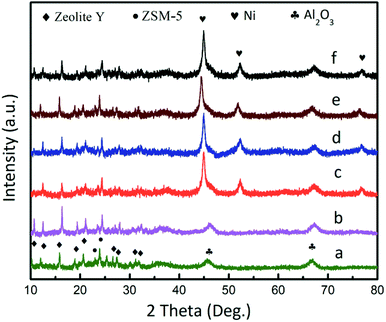 | ||
| Fig. 2 XRD patterns of the DF3C (a), DF3C after calcinations (b), Ni/DF3C (c), 0.05-IL-Ni/DF3C (d), 0.10-IL-Ni/DF3C (e), 0.15-IL-Ni/DF3C (f). | ||
The FT-IR results (Fig. S2†) showed characteristic peaks of [C2OHmim][BF4] at 3557 and 3426 cm−1 resulting from telescoping vibrations of hydroxyl groups. The typical peaks for the imidazole ring were also observed at 1578, 1467, 2965, 2895, 3168, and 3122 cm−1, which are attributed to stretching of CH3(N), stretching of the ring in plane, asymmetric stretching of HCH on the hydroxyethyl group, symmetric stretching of HCCH, asymmetric stretching of ring HCCH, and stretching of NC(H)NCH, respectively. In addition, a characteristic peak of [BF4]− also appeared at 846 cm−1. The peaks at 3557, 3426, and 1648 cm−1 are attributed to bending and stretching vibrations of physically adsorbed water on the surface of the DF3C, whereas those at 2169, 1079, and 464 cm−1 are attributed to Si–H telescopic vibrations, RO4 (R: tetrahedral Si or Al) asymmetric stretching vibrations, and RO bending vibrations, respectively. There was not Si–O(H)–Ni peak at 985 cm−1, which indicated that no covalent bonds formed between Ni and DF3C.
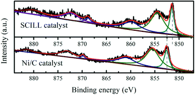
XPS measurements (Fig. 3) were performed on the Ni/DF3C with or without ionic liquid film to better understand high stability and selectivity to cis-pinane of the Ni/DF3C coated with ionic liquid. The binding energy of the Ni 2p3/2 in the Ni/DF3C catalyst were 852.6 eV (Ni0), and 855.6 eV (Ni2+). Notably, these energies were 1.3 eV higher than those in the IL-Ni/DF3C catalytic system. Oxidization of nickel might be attributed to reactions with oxygen in the air during the sample testing, similar to previous reports.36 The differences observed here are attributed to interactions of ionic liquid with the active metal sites. The IL may act as a ligand directly interacting with the catalytically active site.37 The lower binding energy of the SCILL catalyst suggested that [C2OHmim][BF4] directly interacted with the active metal nickel, which could be related to similar effects reported in bimetallic catalysis.38,39 Supported metallic catalysts are generally highly reactive in the hydrogenation of unsaturated compounds; however, the selectivity and stability of such catalysts are generally poor. To increase the selectivity to the product of interest, conventional monometallic catalysts are typically doped with other metals or non-metal elements to regulate the electronic environment of the active components.32 For SCILL-based catalysts, a thin film of ionic liquid covers the active sites of the catalyst and interacts with the active metal by controlling the electron density at the metal sites, where the degree of electron donation correlates with the interionic interactions in the ionic liquids, which in turn controls the activity and selectivity of the catalyst. Schwab et al. used a supported Pd catalyst with an ionic liquid layer in the stereoselective hydrogenation of 2-hexyne to cis-2-hexene and achieved an outstanding yield of 88%.30 Babucci et al. have reported a class of atomically dispersed supported metal catalysts with performance tuned by ionic liquid coatings, where the coatings controlled the electron density of active metal sites.40
The influence of the ionic liquid loading on the activity of the catalyst in the hydrogenation of α-pinene was examined. The conversions of α-pinene over the catalysts with different ionic liquid loadings are shown in Fig. 4. In the hydrogenation of α-pinene, the Ni/DF3C system reached a total pinene conversion within 50 min, whereas, for the SCILL system, the conversion was much lower over the same reaction time. For the 0.20-IL-Ni/DF3C catalyst, the reaction rate was very slow and the conversion of reactants was only 5.63% after 180 min; however, for the 0.15-IL-Ni/DF3C catalysts, 38.51% conversion was achieved within the same time. Comparing the catalytic performance on SCILL and Ni/C catalyst revealed that the active metal nickel on the inner surface of the SCILL catalyst might be partially poisoned by the ionic liquid as the chemical interaction between ionic liquid and metal nickel as the results shown in XPS analysis. As Canova et al.41 have studied that the α-pinene hydrogenation was carried out in the presence of a hydrogenation Ni-based catalyst, wherein to obtain increased stereoselectivity, an effective amount of the reactive surface of the hydrogenation catalyst is inactivated with a catalyst modifier. Since the ionic liquid layer was only a few nm thick, when the ionic liquid loading was less enough, the diffusion inside film will play a minor role in the overall rate.42 As increasing the ionic liquid loading or even as reaction solvent, the ionic liquid might be able to block the active sites and the internal pores of the catalyst, at this time, the mass transfer resistance might not be ignored in the reaction rate.31 In summary, it can be inferred that the mass resistance alone was not the only reason for the reduced reaction rate in SCILL catalytic system, but also the chemical interaction between the [C2OHmim][BF4] layer and the active site on the surface of the SCILL catalyst.
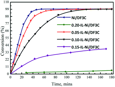 | ||
| Fig. 4 Conversion vs. time profiles. Reaction conditions: α-pinene 60 mL, catalyst 5.0 g, H2 5.0 MPa, 100 °C, 180 min. | ||
The results for selectivity as a function of α-pinene conversion (Fig. 5) indicated that the selectivity toward cis-pinane remained constant throughout the reaction with only minor fluctuations. However, the selectivity of the catalyst varied with different ionic liquid loading. When the loading of the ionic liquid was greater than 10 wt%, the selectivity of the catalyst was more than 98%; however, when the loading of ionic liquid was 5 wt%, the selectivity decreased to approximately 90%. The ionic liquid-free catalyst had a selectivity of approximately 87%. The coating of Ni/DF3C with [C2OHmim][BF4] improved the cis-pinene selectivity further with the activity decreased. The amount of modifier should be sufficient to effect a stereochemical improvement, and yet less than that amount which substantially adversely affects reaction rate and conversion.41 The increase in the cis-pinene selectivity after the application of the ionic liquids could be attributed to the following reasons. The active metal nickel was directly modified by the ligand effects of [C2OHmim][BF4], as confirmed by XPS analysis of IL-Ni/DF3C (Fig. 3). Additionally, a strong electrostatic interfacial field was created by the adsorbed ionic liquid, which generated diffusion barriers and modified the access of different substances into the reaction system.38 The bulky gem-dimethyl bridge group on the α-pinene has a larger steric hindrance, preventing the α-face of α-pinene from making contact with the catalyst.6,43 Hence, hydrogen activated by nickel preferentially attacks the α-face, which is less sterically hindered. Furthermore, the ionic liquid layer might increase the difference of the steric hindrance between α-face and β-face, which improves the cis-pinane selectivity.44
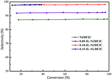 | ||
| Fig. 5 Selectivity vs. conversion profiles. Reaction conditions: α-pinene 60 mL, catalyst 5.0 g, H2 5.0 MPa, 100 °C, 180 min. | ||
This result is attributed to the thickness of the ionic liquid layer, which can be estimated from the mass ratio of the ionic liquid to Ni/DF3C. Interestingly, Cheng et al. have reported that less than a monolayer IL coating on the surface of the catalysts as the mIL/mcatalyst ration is below 0.10, and multilayer IL coatings when the ratio is above 0.10, and his conclusions are a good explanation for our experimental results.35 The thickness of the ionic liquid layer was estimated by using eqn (3)45
 | (3) |
| IL loading (wt%) | 0 | 5 | 10 | 15 | 20 |
| MLs | 0 | 0.37 | 1.15 | 4.51 | 27.60 |
To further study the effect of the catalyst coated with ionic liquid on the hydrogenation of α-pinene, several parameters such as reaction temperature and H2 pressure were studied, and the results were shown in Fig. S3.† The catalytic performances of 0.10-IL-Ni/DF3C in α-pinene hydrogenation at different temperatures under H2 pressure of 5 MPa are shown in Fig. S3A.† At a lower temperature of 70 °C, the conversion was low at 15.77%. As the reaction temperature increased from 70 to 100 °C, the conversion gradually increased and when the temperature was 100 °C, the conversion reached above 99%; however, the cis-pinane selectivity remained at approximately 98% with a slight decrease. It's worth noting that the ionic liquid used in our catalytic system under mild conditions (the maximum reaction temperature was 110 °C) was thermal stable according to a literature reported by Cao et al.48 Thus, it may be concluded that higher temperatures increased conversion but had no notable effects on catalyst selectivity, which is consistent with previous reports in the literature.49 Hydrogenation of α-pinene was performed at different H2 pressures from 2 to 7 MPa, and the results of conversion of α-pinene and selectivity to cis-pinane are shown in Fig. S3B.† The conversion increased markedly as the H2 pressure was increased and at 5 MPa the conversion reached 99.26%. In addition, the selectivity for cis-pinane increased slightly with increasing H2 pressure. The findings presented herein and their discussion, indicate that the reaction temperature and H2 pressure had not distinct effects on the selectivity for cis-pinane, but played an important role in the reaction rate and conversion.
Because the ionic liquid molecule could be synthesized according to the actual needs, so far, various ionic liquids have been prepared. The conventional ionic liquid 1-butyl-3-methylimidazolium tetrafluoroborate ([BMIM][BF4]), 1-ethyl-3-methylimidazolium tetrafluoroborate, ([EMIM][BF4]), etc. have been always used as a stabilizer to protect the metal nanoparticles catalysts (NPs) from aggregating to prolong the lifetime of the NPs catalyst. Zhao et al. have synthesized well-dispersed NiO nanoparticles with room temperature ionic liquid [BMIM][BF4].50 One of the attractive features of ionic liquids is the option to modify them to maximize their benefits in specific reactions and a variety of functionalized ILs are now available.51 Functionalized ILs have a more unique function than traditional ionic liquid. Xue Yang et al. has studied the biphasic hydrogenation over Rh nanoparticles in hydroxyl functionalized ionic liquid (OH-ILs).51 For the α-pinene hydrogenation over SCILL catalysts, we have studied the conventional ionic liquid [EMIM][BF4] and corresponding hydroxylated ionic liquid [C2OHmim][BF4] as modifier for the Ni/DF3C catalyst with the same thick 1 ML, the results were listed in Table S1.† Almost all the reactant was converted in 180 min over these three catalysts, although, maybe there were some difference in reaction rate which have been particularly discussed above. And we could found that the selectivity toward cis-pinane over [EMIM][BF4]-Ni/DF3C was similar to that of Ni/DF3C without ionic liquid layers. However, for the [C2OHmim][BF4]-Ni/DF3C, the selectivity toward cis-pinane increased to approximately 98%, which could be attributed to some special performance of the functional ionic liquid such as viscosity, boiling point, melting point, electrochemical environment and electrochemical interaction between metal particles and ionic liquid. Ethanol has been used as solvent in general hydrogenation reaction and especially for the pinene hydrogenation.1 Cocker et al. has studied the hydrogenation of α-pinene over Pt/C (5 wt%) catalyst with EtOH as solvent and obtained high selectivity for cis-pinane (98.5%).44 Dorjnamjin et al. have used the OH-ILs as a reducing agent which reduces the Ag ion to Ag0 as well as a stabilizer in forming Ag nanoparticles, and the –CH2OH– group in OH-ILs is converted to the –CHO– group by reducing Ag ion and protects the Ag nanoparticles at the same time.52 For the SCILL catalytic system, the –OH functional group was grafted in the traditional ionic liquid [EMIM][BF4], making the SCILL catalytic performance was similar to the case of using EtOH as reaction solvent, at the same time, the lifetime of the catalyst was prolonged as a result of the OH-ILs protection.52
The work also studied varies of catalysts for the hydrogenation of α-pinene at the same conditions as shown in Table 3. It can be seen that the hydrogenation of α-pinene was difficult to take place without the catalyst (entry 1). Ni/DF3C and Pd/C showed excellent catalytic efficiency, the conversion of the α-pinene could reach over 99%, however, the selectivity toward cis-pinane was below 90%. For 0.10-IL-Ni/DF3C, the α-pinene conversion and cis-pinane selectivity were over 99% and 98%, respectively. Hou et al. have studied the α-pinene hydrogenation over the Ru nanoparticles, and the selectivity for cis-pinane could reach above 98%.53 Yang et al. applied the Pd-based catalyst for the hydrogenation of the α-pinene, and the conversion and selectivity could reach 99.4% and 81.3%, respectively.49 In summary, metal Ni, Pt, Ru-based catalysts47 could achieve high α-pinene conversion and selectivity (over Ni-SCILL and Ru-based catalyst), but the price of these three kinds of metal catalysts was greatly different, metal Ni is very cheap compared with other noble metal like Pt, Ru, etc. It was possible to teach a cheap Ni-based catalyst to act like an noble Ru metal catalyst for hydrogenation reaction by coating it with an ionic liquid film.32
| Entry | Catalyst | X (%) | S (%) |
|---|---|---|---|
| a Reaction conditions: α-pinene 60 mL, catalyst 5 g, H2 5.0 MPa, 100 °C, 180 min. X: conversion of α-pinene; S: selectivity toward cis-pinane.b Commercial Pd/C (5%), the molar ratio of the Pd to α-pinene was similar to the case of Ni-based catalyst.c The experimental data was obtained from ref. 47. | |||
| 1 | Blank | 1.70 | 72.36 |
| 2 | Ni/DF3C | 99.47 | 87.94 |
| 3 | 0.10-IL-Ni/DF3C | 99.06 | 98.26 |
| 4b | Pd/C | 99.31 | 88.91 |
| 5c | Ru/C | 98.10 | 96.0 |
Finally the reusability of the catalyst coated with or without ionic liquid was also investigated for the hydrogenation of α-pinene (Fig. 6). The recycled catalyst was easily removed from the reaction mixture by simple vacuum filtration for the next cycle. The conversion of α-pinene was maintained at approximately 99.0% throughout the first 13 cycles for the SCILL system, indicating its excellent stability; however, in the case of the Ni/DF3C catalytic system, the conversion steadily decreased from 99.8% to 62.5% after fourth cycles. Moreover, after 13 cycles, the activity of IL-Ni/DF3C began to decrease, the conversion eventually decreased to 84.3% and the selectivity also decreased from 98.2% to 87.5%. The decrease of activity and selectivity might be explained by the loss of ionic liquid from the catalyst over multiple runs owing to weak interactions between the ionic liquid and the Ni/DF3C as the earlier literature reported that it should be further emphasized that even a very low solubility of the ionic liquid in the flowing liquid media will make long term stability of the SCILL catalyst system impossible due to slow but steady leaching.34 As shown in Fig. S4,† The SCILL catalyst used after 20 runs has approximately 4% weight loss, which corresponds to the residual ionic liquid on the surface of the catalyst. The quality of the residual ionic liquid estimated by the thermogravimetric analysis may not be accurate enough, but it could reflect the fact of the leaching loss of ionic liquid during the multiple cycles of reaction as reported in some literature.34,42,54 Overall, these studies demonstrate greatly enhanced reusability and selectivity of the IL-Ni/DF3C catalyst, which is attributed to the effects of the ionic liquid layer.
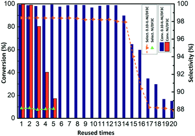 | ||
| Fig. 6 Recycling of the Ni/DF3C coated with or without ionic liquid. Reaction conditions: α-pinene 30 mL, catalyst 2.5 g, H2 5 MPa, 100 °C, 90 min. | ||
Conclusion
In the present study, SCILL catalysts were prepared from waste industrial catalysts, solvent ionic liquid, and the non-precious metal nickel for successful application to catalysis of α-pinene hydrogenation. To explore the mechanism of the catalyst, a series of characterization tests were performed on the catalyst. The XPS analysis confirmed that [C2OHmim][BF4] donated electron density to the nickel in the catalysts, which changed the electronic properties of the active site and likely contributed to the improved selectivity to cis-pinane and greater cycling stability. In the catalyst performance tests, the ionic liquid layer also inhibited the reaction rate to some extent and improved the selectivity to cis-pinane above 98%. When the loading of the ionic liquid was approximately 10 wt%, the yield of cis-pinane improved above 97% under the optimal catalyst and reaction conditions. Furthermore, the SCILL catalyst could be recovered easily and reused for up to 13 runs without a notable loss of the catalytic activity and selectivity. The designable molecular structure of the ionic liquid and range of immobilization modes will make it possible to design SCILL catalysts with high activity, high selectivity, and long lifetime for hydrogenation of α-pinene and other reactions in the future.Conflicts of interest
There are no conflicts to declare.Acknowledgements
The authors are grateful for the financial support for this work from the National Natural Science Foundation of China (Grant No. 21878056, 31560241), Key Laboratory of Petrochemical Resource Processing and Process Intensification Technology (Grant No. 2016Z002).References
- A. Selka, N. A. Levesque, D. Foucher, O. Clarisse, F. Chemat and M. Touaibia, Org. Process Res. Dev., 2017, 21, 60–64 CrossRef CAS.
- S. Hou, X. Wang, C. Huang, C. Xie and S. Yu, Catal. Lett., 2016, 146, 580–586 CrossRef CAS.
- A. Milewska, A. M. B. Osuna, I. M. Fonseca and M. N. da Ponte, Green Chem., 2005, 7, 726–732 RSC.
- I. V. Deliy and I. L. Simakova, Russ. Chem. Bull., 2008, 57, 2056–2064 CrossRef CAS.
- I. L. Simakova, Y. Solkina, I. Deliy, J. Wärnå and D. Y. Murzin, Appl. Catal., A, 2009, 356, 216–224 CrossRef CAS.
- S. Tanielyan, N. Biunno, R. Bhagat and R. Augustine, Top. Catal., 2014, 57, 1564–1569 CrossRef CAS.
- K. R. Vuyyuru, K. K. Pant, V. V. Krishnan and K. D. Nigam, Ind. Eng. Chem. Res., 2010, 49, 2014–2024 CrossRef CAS.
- F. Ferella, V. Innocenzi and F. Maggiore, Resour., Conserv. Recycl., 2016, 108, 10–20 CrossRef.
- Y. Cao and T. Mu, Ind. Eng. Chem. Res., 2014, 53, 8651–8664 CrossRef CAS.
- B. Wang, L. Qin, T. Mu, Z. Xue and G. Gao, Chem. Rev., 2017, 117, 7113–7131 CrossRef CAS PubMed.
- Z. Xue, L. Qin, J. Jiang, T. Mu and G. Gao, Phys. Chem. Chem. Phys., 2018, 20, 8382–8402 RSC.
- B. Sánchez, C. Calderón, C. Garrido, R. Contreras and P. R. Campodónico, New J. Chem., 2018, 42, 9645–9650 RSC.
- A. A. Elgharbawy, F. A. Riyadi, M. Z. Alam and M. Moniruzzaman, J. Mol. Liq., 2018, 251, 150–166 CrossRef CAS.
- S. Tiwari, N. Khupse and A. Kumar, J. Org. Chem., 2008, 73, 9075–9083 CrossRef CAS PubMed.
- C. W. Duan, L. X. Hu and J. L. Ma, J. Mater. Chem. A, 2018, 6, 6309–6318 RSC.
- P. Zhang, X. Tian and D. Fu, Energy, 2018, 161, 1122–1132 CrossRef CAS.
- U. Domańska, A. Wiśniewska, Z. Dąbrowski and M. Więckowski, J. Mol. Liq., 2018, 255, 504–512 CrossRef.
- M. J. Jacinto, P. Djs, I. M. Marrucho, J. Gonã§Alves, R. C. Willson, A. M. Azevedo and M. R. Aires-Barros, J. Chromatogr. A, 2018, 1532, 246–250 CrossRef CAS PubMed.
- Y. Zhang, X. Ji, Y. Xie and X. Lu, Appl. Energy, 2018, 217, 75–87 CrossRef CAS.
- Y. Zhao, M. Pan, X. Kang, W. Tu, H. Gao and X. Zhang, Chem. Eng. Sci., 2018, 189, 43–55 CrossRef CAS.
- A. J. Lucio and S. K. Shaw, Analyst, 2018, 143, 4887–4900 RSC.
- M. C. Buzzeo, R. G. Evans and R. G. Compton, ChemPhysChem, 2004, 5, 1106–1120 CrossRef CAS PubMed.
- H. Wan, H. Yin, L. Lin, X. Zeng and A. J. Mason, Sens. Actuators, B, 2018, 255, 638–646 CrossRef CAS PubMed.
- X. Zhao, J. Jiang, Z. Xue, C. Yan and T. Mu, Chem. Commun., 2017, 53, 9418–9421 RSC.
- W. Zhao, Z. Xue, J. Wang, J. Jiang, X. Zhao and T. Mu, ACS Appl. Mater. Interfaces, 2015, 7, 27608–27612 CrossRef CAS PubMed.
- Z. Li, R. Li, T. Mu and Y. Luan, Chem.–Eur. J., 2013, 19, 6005–6013 CrossRef CAS PubMed.
- R. A. Brown, P. Pollet, E. McKoon, C. A. Eckert, C. L. Liotta and P. G. Jessop, J. Am. Chem. Soc., 2001, 123, 1254–1255 CrossRef CAS PubMed.
- H. Konnerth and M. H. G. Prechtl, Green Chem., 2017, 19, 2762–2767 RSC.
- U. Kernchen, B. Etzold, W. Korth and A. Jess, Chem. Eng. Technol., 2007, 30, 985–994 CrossRef CAS.
- F. Schwab, N. Weidler, M. Lucas and P. Claus, Chem. Commun., 2014, 50, 10406–10408 RSC.
- R. Hou, X. Lan and T. Wang, Catal. Today, 2015, 251, 47–52 CrossRef CAS.
- A. Jalal and A. Uzun, J. Catal., 2017, 350, 86–96 CrossRef CAS.
- L. C. Branco, J. N. Rosa, J. J. Moura Ramos and C. A. Afonso, Chem.–Eur. J., 2002, 8, 3671–3677 CrossRef CAS.
- T. Selvam, A. Machoke and W. Schwieger, Appl. Catal., A, 2012, 445–446, 92–101 CrossRef CAS.
- Q. Cheng, S. Xu, X. Wang and C. Guo, Chem. Eng. Technol., 2013, 36, 228–232 CrossRef CAS.
- A. Jalal and A. Uzun, J. Catal., 2017, 350, 86–96 CrossRef CAS.
- M. Sobota, M. Happel, M. Amende, N. Paape, P. Wasserscheid, M. Laurin and J. Libuda, Adv. Mater., 2011, 23, 2617–2621 CrossRef CAS PubMed.
- T. Bauer, S. Mehl, O. Brummel, K. Pohako-Esko, P. Wasserscheid and J. Libuda, J. Phys. Chem. C, 2016, 120, 4453–4465 CrossRef CAS.
- Y. Zhang, Y. Qi, Z. Yin, H. Wang, B. He, X. Liang, J. Li and Z. Li, Green Chem., 2018, 20, 3944–3953 RSC.
- M. Babucci, C.-Y. Fang, A. S. Hoffman, S. R. Bare, B. C. Gates and A. Uzun, ACS Catal., 2017, 7, 6969–6972 CrossRef CAS.
- L. A. Canova, US Pat. 4018842, 1977.
- N. C. Antonels, M. Benjamin Williams, R. Meijboom and M. Haumann, J. Mol. Catal. A: Chem., 2016, 421, 156–160 CrossRef CAS.
- M. L. Casella, G. F. Santori, A. Moglioni, V. Vetere, J. F. Ruggera, G. M. Iglesias and O. A. Ferretti, Appl. Catal., A, 2007, 318, 1–8 CrossRef CAS.
- W. Cocker, P. V. R. Shannon and P. A. Staniland, J. Chem. Soc. C, 1966, 41–47 RSC.
- Q. Cheng, S. Xu, X. Wang and C. Guo, Chem. Eng. Technol., 2013, 36, 228–232 CrossRef CAS.
- T. Cremer, M. Stark, A. Deyko, H. P. Steinrück and F. Maier, Langmuir, 2011, 27, 3662–3671 CrossRef CAS PubMed.
- Y. Liu, L. Li, C. Xie, S. Yu and S. Liu, Chem. Eng. J., 2016, 303, 31–36 CrossRef CAS.
- Y. Cao and T. Mu, Ind. Eng. Chem. Res., 2014, 53, 8651–8664 CrossRef CAS.
- Y. Yang, X. Liu, D. Yin, Z. Zhang, D. Lei and J. Yang, J. Ind. Eng. Chem., 2015, 26, 333–334 CrossRef CAS.
- M. Zhao, N. Li, L. Zheng, G. Li and L. Yu, J. Dispersion Sci. Technol., 2008, 29, 1103–1105 CrossRef CAS.
- X. Yang, N. Yan, Z. Fei, R. M. Crespo-Quesada, G. Laurenczy, L. Kiwi-Minsker, Y. Kou, Y. Li and P. J. Dyson, Inorg. Chem., 2008, 47, 7444–7446 CrossRef CAS PubMed.
- D. Dorjnamjin, M. Ariunaa and Y. K. Shim, Int. J. Mol. Sci., 2008, 9, 807–820 CrossRef CAS PubMed.
- S. Hou, C. Xie, H. Zhong and S. Yu, RSC Adv., 2015, 5, 89552–89558 RSC.
- T. Gallert, M. Hahn, M. Sellin, C. Schmöger, A. Stolle, B. Ondruschka, T. F. Keller and K. D. Jandt, ChemSusChem, 2011, 4, 1654–1661 CrossRef CAS PubMed.
Footnote |
| † Electronic supplementary information (ESI) available. See DOI: 10.1039/c9ra00675c |
| This journal is © The Royal Society of Chemistry 2019 |

