 Open Access Article
A comprehensive review of recent developments in 3D printing technique for ceramic membrane fabrication for water purification
Hitesh Dommati†
abc,
Saikat Sinha Ray†
d,
Jia-Chang Wang
*abc and
Shiao-Shing Chen
 *d
*d
aDepartment of Mechanical Engineering, National Taipei University of Technology, Taiwan. E-mail: jcw@mail.ntut.edu.tw
bAdditive Manufacturing Center for Mass Customization Production, National Taipei University of Technology, Taiwan
cCollege of Mechanical & Electrical Engineering, National Taipei University of Technology, Taiwan
dInstitute of Environmental Engineering and Management, National Taipei University of Technology, Taiwan. E-mail: f10919@ntut.edu.tw
First published on 29th May 2019
Abstract
Additive manufacturing (AM), which is also commonly known as 3D printing, provides flexibility in the manufacturing of complex geometric parts at competitive prices and within a low production time. However, AM has not been used to a large extent in filtration and water treatment processes. AM results in the creation of millions of nanofibers that are sublayered on top of each other and compressed into a thin membrane. AM is a novel technique for fabricating filtration membranes with different shapes, sizes and controlled porosity, which cannot be achieved using conventional process such as electrospinning and knife casting. In this paper, we review the advantages and limitations of AM processes for fabricating ceramic membranes. Moreover, a brief background of AM processes is provided, and their future prospects are examined. Due to their potential benefits for fabrication and flexibility with different materials, AM methods are promising in the field of membrane engineering.
1. Introduction
In additive manufacturing (AM), a 3D part with complex geometry is built through the layer-by-layer deposition of material.1 The introduction of new materials has considerably broadened the applications of AM. Currently, AM is being applied in various fields, such as prototyping, education, manufacturing, biomedicine, pharmaceuticals, architecture, construction, military, and aerospace. In contrast to the conventional subtractive manufacturing process, AM can be used to fabricate complex geometries, such as net-shaped parts with extreme overhangs and porous structures. Currently, a wide range of materials, such as thermoplastics,2 photopolymers3 ceramics,4 metals,5 and clay,6 can be used in AM. Different AM processes require materials in different phases, and the change in material phases depends on the process.1.1 Brief history
In 1981, a Japanese inventor named Hideo Kodama registered the first ever 3D printing technology through the additive process. Kodama developed a system in which ultraviolet (UV) light was used to harden polymers and create solid objects; this was the first step toward stereolithography (SLA).1 Charles Hull, who is considered the father of SLA, used a process similar to 3D printing to produce smaller versions of products, which can be tested before spending money, energy, and time on producing the actual version. Typically, in this process, the object is printed layer-by-layer by using computer-aided designs (CADs) to create 3D models, which are then rinsed with a solvent and hardened with UV light.Selective laser sintering (SLS) is an advanced form of the 3D printing process. In general, it involves using AM and a powder polymer to create objects. Fused deposition modeling (FDM), which was developed by Scott Crump, is one of the most common 3D printing techniques till date. FDM is also known as “desktop 3D printing” because desktops are most commonly utilized in this technology. In this process, the printer heats a cable of thermoplastic into the liquid form and extrudes it layer-by-layer to create an object. Thus, 3D printing has transformed and advanced over the past three decades. The aforementioned description of the three processes provides a brief history of 3D printing. These processes allow virtually anything to be fabricated by designing a simple 3D model.7
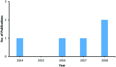
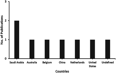
Since the last 5 years, the 3D printing technique has attracted considerable attention probably due to its potential benefits in the printing of 3D membranes for water filtration. AM techniques provide increased control over the architecture of filtration membrane systems and can be considered novel membrane fabrication techniques. They can be used to cast membranes of various designs, shapes, architectures, and types, which cannot be achieved through conventional processes such as electrospinning and phase inversion. A survey of peer-reviewed research articles related to “3D membranes” and “water filtration” in the previous 5 years is illustrated in Fig. 1. Moreover, the number of publications related to 3D-printed membranes for water filtration from various countries is indicated in Fig. 2. Saudi Arabia is leading country contributing to such research as per the advanced Scopus search database. The number of publications clearly illustrates that the 3D printing technique has received much attention in recent years for membrane fabrication.
1.2 Background
AM can be used to fabricate any complex design. In the last decade, many AM systems have been developed, and they feature high adaptability for more than one material. Materials such as high-performance ceramics, photopolymers, graphene, metals, and composite materials have attracted considerable attention and have been used in major innovations in various applications. However, limited studies have applied AM for membrane fabrication. Tan et al. reviewed the use of solid, liquid, and powder loadings in the AM method for membrane spacer fabrication.8 Tan et al. concluded that spacers fabricated using the FDM, SLS, and Polyjet processes exhibited superior performance to commercially available spacers in terms of mass transfer and critical flux. Fee et al.,9 used AM to fabricate porous media with finely packed morphology through UV-curing of acrylonitrile–butadiene–styrene powder layers. Fee et al. indicated that AM methods can be successfully used to produce precisely controlled porous media and are applicable in flow distribution. Siddiqui et al.10 fabricated feed spacers for spiral-wound membrane systems by using the AM process and characterized the spacers. They found that the spacers improved the cleanability of spiral-wound nanofiltration (NF) and reverse osmosis (RO) membrane systems by reducing the formation of biofilms over them.Although membranes have been successfully fabricated using AM, AM is limited by either the materials required or the porosity and size of the work pieces. Nonmetallic materials such as ceramics, polymers, thermoplastics, and composites have been used in AM. 3D Printing enables the precise control over fabrication of any complex object and provides flexibility over resolution, porosity, layer thickness, materials and design. 3D printing a ceramic membrane for water filtration enables to fabricate long lasting membranes with improved design structure and better performance than conventional membranes. The 3D printed ceramic parts are tend to possess high mechanical properties and non-reactive to external agents. This makes them more suitable for indulging with bacteria killing agents to improve the filtration process. By 3D printing ceramic membranes design the filtration process can be improved by controlling the pore density layer wise with different grain sizes of the structure particles. Therefore, various AM processes have been introduced for building objects with a wide variety of precisely controlled porosities. These processes are applicable for different water treatment applications, such as microfiltration (MF), ultrafiltration (UF), NF, RO, forward osmosis, and membrane distillation (MD).
2. Why the AM technique?
In this review, membrane fabrication methodologies for pressure-driven membrane processes and MD are discussed in detail. To enhance membrane performance, modifications are required for commonly used membrane fabrication methodologies, such as phase inversion, electrospinning, and track etching.11 However, the selection of an optimal methodology for membrane fabrication depends on the chemical nature of the polymer and desired shape and structure of the membrane.2.1 Various state-of-art membrane fabrication techniques
Phase inversion is a well-known method for controlling polymer transformation from a liquid phase to a solid phase. Typically, four processes are used to produce phase-inversion-based membranes: (a) precipitation from the vapor phase, (b) precipitation through controlled evaporation, (b) thermally induced phase separation, and (d) immersion precipitation.(a) Precipitation from the vapor phase: In this technique, a polymer and solvent are mixed and placed in a vapor atmosphere, where the vapor phase consists of a nonsolvent saturated with the used solvent. The high solvent concentration in the vapor phase prevents the evaporation of the solvent from the fabricated layer. The membrane forms due to the diffusion of the nonsolvent into the cast film.
(b) Precipitation through controlled evaporation: In this technique, polymeric pellets are dissolved in a mixture of a nonsolvent and solvent. Evaporation occurs because the solvent is considerably more volatile than the nonsolvent. As a result, polymer precipitation occurs because the nonsolvent content is higher than the solvent content.12
(c) Thermally induced phase separation: Polymeric pellets are mixed with one or multiple solvents. The mixture is then cooled to allow phase separation to occur. Typically, evaporation of the solvent leads to the formation of a film.13
(d) Immersion precipitation: Immersion precipitation is one of the most commonly used phase inversion techniques. This technique is also known as nonsolvent-induced phase inversion. In this technique, a film of homogenous polymeric solution is cast on a flat surface (substrate). Then, the cast film is placed in a coagulation bath containing DI water or methanol. Typically, precipitation occurs due to the exchange between the solvent and nonsolvent.14
Electrospinning is a commonly used technique for fabricating fibrous tissue engineering scaffolds, which are also known as electrospun membranes or electrospun nanofibers. In the electrospinning technique, an electric field is used to create a charged jet of polymer solution. By increasing the applied voltage, the fiber jet is ejected from the apex of the Taylor cone when the electrostatic force is higher than the surface tension. Moreover, the solvent evaporates during ejection and elongation processes. The elongation and evaporation of the solvent reduces the scale of the fiber diameter from micrometers to nanometers. Finally, the produced polymeric nanofibrous material is attracted by a metallic collector.15 In general, the electrospun nanofibrous membrane possesses the following advantages:
(a) Large surface-area-to-pore-volume ratio: Electrospun nanofibrous material has a high surface-area-to-pore-volume ratio, which makes it a very promising material for the fabrication of sensors and membranes, where a high surface area is required.
(b) Ease of material combination: Various materials can be easily combined for the production of nanofibers.
(c) Large-scale production capability: Till date, many research centers and companies have used the electrospinning technique to produce nanofibrous membranes on a large scale.
(d) Commercial applications: The electrospinning technique is used in the production of several commercially available products, such as air filtration membranes, face masks, water filtration membranes, cell culture plates, and wound care patches.
2.2 Overview of additive manufacturing technique
The 3D printing technique or AM process has emerged as an efficient technique for manufacturing membranes with desired characteristics. In 3D printing, a computer commands successive layers of material to accumulate and form a computed design. In traditional manufacturing based on molds and fixed processes, the same object tends to be produced repeatedly. However, the 3D printing technique can be used to produce a specifically designed membrane. Since the previous decade, 3D printing has advanced to the point where it can control the resolution and precision of membrane fabrication. AM can be used to fabricate microstructure and macrostructure membranes, offering the effectiveness for integrated design between the materials utilized and their purposes.16To determine the appropriateness of AM techniques for membrane fabrication, various features of the processes must be considered. The following features are desired for ceramic membrane fabrication:
(1) A high resolution is required.
(2) High accuracy and precision are required to 3D print the designed membrane.
(3) A large membrane whose size is similar to that of an actual membrane should be produced.
(4) The production time of the membrane must be as low as possible.
(5) For ease of selection of materials, commonly used materials must be given high priority for membrane fabrication.
(6) The mechanical properties should enable membranes to withstand high pressure processes (1–40 bar).
(7) The technique used must be more economic than the phase inversion technique for membrane fabrication.
Table 1 indicates the different state-of-art techniques available for membrane fabrication. Using this table, researchers and beginners can select a suitable casting method for shaping their membrane as well as utilize the membrane for various purposes, which plays a key role in separation and purification performance. The main focus of this review is to indicate the prominent advantages of the AM technique. In addition to that, the other conventional membrane fabrication techniques possess lot of drawbacks including limited options of materials, time consuming, non-uniformity and mechanically unstable. Although, the AM technique possesses a few drawbacks, such as scalability and high computational load. These drawbacks can be considered in future studies. The AM technique is more suitable than other conventional techniques for membrane fabrication (Table 1).
| Techniques available | Types | Advantages | Disadvantages | References |
|---|---|---|---|---|
| Phase inversion technique | (1) Precipitation from vapor phase | ✓ Rapid film formation | ✓ Limited for specific polymers or polymeric solution | 17 |
| (2) Precipitation by controlled evaporation | ✓ Inexpensive technique | ✓ No-uniformity in pore size distribution | ||
| (3) Thermally induced phase separation; and | ✓ Utilized at industrial scale | ✓ Uncontrolled pore size, pore diameter or pore width | ||
| (4) Immersion precipitation | ✓ Uniform thickness distribution | ✓ Time consuming technique | ||
| ✓ Good flatness | ||||
| ✓ Long term stability | ||||
| Electrospinning technique | (1) Coaxial electrospinning | ✓ Comparatively lower startup cost | ✓ Process depends on many parameters | 18 |
| (2) Emulsion electrospinning | ✓ Larger surface area to pore volume ratio | ✓ Utilized solvents can be toxic in nature | ||
| (3) Melt electrospinning | ✓ Easily combined with different materials | ✓ Jet instability | ||
| ✓ Large scale production | ✓ Non-uniform pore distribution | |||
| ✓ Ease of nano-fiber functionalization | ✓ Mechanically less stable | |||
| ✓ Availability of various polymers to produce nanofibrous material | ✓ Time consuming technique | |||
| Additive manufacturing technique or 3D printing technique | (1) Stereolithography (SLA) | ✓ Speed | ✓ Scalability of AM technique is doubtful | 16 |
| (2) Direct Light Processing (DLP) | ✓ Single step production | ✓ High computational load | ||
| (3) Continuous DLP (CDLP) | ✓ Cost effective | ✓ Long printing times | ||
| ✓ Less complexity and design freedom | ||||
| ✓ Ease of access | ||||
| ✓ Sustainability | ||||
| ✓ Risk mitigation | ||||
| ✓ Desirable thickness |
The AM technique is based on one-step production. The ability to produce the product (ceramic membrane) in a single step considerably decreases the dependence on different manufacturing processes (such as welding, machining, and painting) and provides the designer increased control over the final product. Fig. 3 illustrates a comparison of the 3D printing technique with conventional manufacturing processes. The 3D printing technique helps manufacturers reduce unnecessary manufacturing steps and use one device to create geometrically complex products. The single-step AM technique represents the next level of manufacturing and the next generation of design, optimization, and validation.19
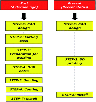 | ||
| Fig. 3 The past and present scenario of AM technique compared to the traditional manufacturing process. | ||
3. AM techniques and specifications
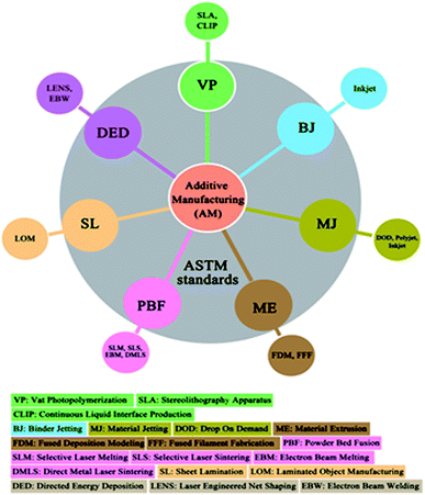
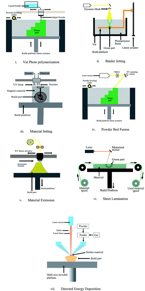
As per ASTM standards, AM processes are classified into seven categories as indicated in Fig. 4.1 The processes are classified according to the material deposition method, curing technique, and binding mechanism. Different AM processes exhibit different process parameters, including fabrication speed, surface finish, mechanical strength, build volume, and layer resolution. However, these parameters are partially dependent on the type of material being used and its state.3.1 Classifications of AM methods
In addition to ASTM standards for classifying AM processes, reviewers have also classified AM processes according to the fabrication type (direct or indirect fabrication);20 material state – liquid, solid or powder.21 In this study, this ASTM classification is considered as the standard for AM methods. The advantages, disadvantages, and applications of all the AM methods are described in Table 3. The seven types of AM processes are as follows:| Process | Material | Porosity | Applications | References |
|---|---|---|---|---|
| VP | Bioactive glass and poly (ε-caprolactone) | 63–77 vol% | Microfiltration and particle filtration | 23 |
| Silica | 33.3 vol% | Microfiltration | 24 | |
| Al2O3–ZrO2 | 36 vol% | Microfiltration | 25 | |
| MJ | Polycaprolactone | 92% | Microfiltration | 26 |
| PZT | 1 vol% | Particle filtration | 27 | |
| BJ | Si3N4 | 60–70 vol% | Particle filtration | |
| Tricalcium phosphate | 42–63 vol% | Microfiltration | 28 | |
| Polyethylene | 23–40 vol% | Microfiltration | 29 | |
| ME | Alumina and other ceramics | 1.5 vol% | Particle filtration | 30 |
| Stratasys ABS (P400) | ∼50.7 vol% | Microfiltration | 31 | |
| Polycaprolactone | 48–77% | Microfiltration | 32 | |
| PBF | Al2O3 | 34 vol% | Microfiltration | 33 |
| Polycaprolactone | 37–55% | Particle filtration | 32 | |
| SL | Al2O3 | 2.9 vol% | Particle filtration | 34 |
| Si–SiC | 69.4 vol% | Microfiltration | 35 | |
| DED | Ti, NiTi | 12–42 vol% | Particle filtration and microfiltration | 36 |
| AM process | Materials used | Advantages | Disadvantages | Applications | References |
|---|---|---|---|---|---|
| Vat Photopolymerization (VP) | Photopolymers like acrylate based resins, ceramics, thermoplastics, biomaterials, hydrogels (Chan et al., 2012) | (1) High-resolution parts can be fabricated with feature sizes minimum of 0.2–20 μm | (1) Low build volumes for ceramic structures | Casting, prototyping, tissue scaffolds, microfluidics, dentistry, etc. | 45 |
| Commercial machines: carbon 3D – CLIP technology, 3D systems – projet series, Formlabs Form 1&2, etc. | (2) SLA is relatively a fast fabrication process | (2) Usage of support structures for complex overhangs is necessary | |||
| (3) Less energy consumption | (3) Final parts are not functional grade | ||||
| Binder Jetting (BJ) | Ceramics – alumina, zirconia, etc.; metals – SS, cobalt chrome, etc.;46 polymers, silica, metal–metal and metal–ceramic composites etc. | (1) No support structures are required for the complex overhangs | (1) Rough surface finishing; for smoother surface, additional post processing is required | Tissue engineering, fuel cell fabrication, robotic structures, etc. | 47 |
| Commercial machines: Voxeljet, Exone, 3D systems-CJP, etc. | (2) Flexible to adapt different types of materials | (2) Poor mechanical strengths | |||
| (3) Large build volumes are possible | (3) High porosity of the final parts | ||||
| (4) Color printing is possible for polymer materials | |||||
| Material Jetting (MJ) | Simulated ABS, polypropylene, polycaprolactone, plastic, flexible materials, ceramics, etc. | (1) Possibility of fabrication using multi-materials together | (1) MJ system expensive; that may directly affect the price of the final part | Dentistry, educational purposes, drug manufacturing, low cost antenna manufacturing, wax casting, multi-color printing | 48 |
| Commercial machines: Stratasys Polyjet, 3D systems MJM, Solidscape, etc. | (2) Homogenous mechanical and thermal properties | (2) Requires additional post processing | |||
| (3) High dimensional accuracy | (3) Poor mechanical properties | ||||
| (4) Full color 3D printing is possible | (4) Low durability | ||||
| Material Extrusion (ME) | Thermoplastics like ABS, PLA, nylon, etc.; clay, porcelain, concrete, etc. | (1) Wide range of materials which are abundantly available for very economic prices | (1) Requires additional support structures for overhangs | Educational, construction, architecture, prototyping, etc. | 49 |
| Commercial machines: Ultimaker, RepRap, Stratasys, Markforged, etc. | (2) Most affordable system and fabrication process | (2) Requires additional post processing for cleaning the support structures | |||
| (3) Lead time is short | (3) Poor surface finishing | ||||
| (4) Possible to build large volumes | (4) Lower durability | ||||
| Powder Bed Fusion (PBF) | Plastics & polymers – nylon, TPU, glass filled nylon; metals – SS, titanium, inconel, etc.;50 ceramics – zirconia, alumina, silicon nitride,51 etc. | (1) Highly durable parts | (1) Tall structures are prone to damage while fabrication | Aerospace applications, machine tools, automotive applications, medical implants, etc. | 50 |
| Commercial machines: Arcam A2X, Q20; EOS M 280, 290; Renishaw AM250, Concept Laser – mLab, etc. | (2) Wide range of materials are available | (2) Addition surface finishing is required post 3D printing process | |||
| (3) High mechanical properties are achievable | (3) For hollow cavities perforation is required to drain the non-sintered material | ||||
| (4) Composite materials are adaptable | |||||
| (5) Direct functional grade parts can be manufactured | |||||
| Sheet Lamination (SL) | Paper, alumina, titanium composites,52 copper | (1) The parts are able to be printed in the whole color spectrum | (1) Very poor durability due to the binding material degradation | Educational, architecture prototyping, etc. | 22, 52 and 53 |
| Commercial machines: mCor, Fabrisonic, etc. | (2) No state change of the materials is required in this process | (2) Impossible to print overhang structures | |||
| (3) Very economical process | (3) Poor mechanical properties | ||||
| Directed Energy Deposition (DED) | Metals – cobalt chromium, SS, titanium, etc.; ceramics – alumina, zirconia, other oxides, silicon nitride, HAP, etc. | (1) Very high mechanical properties | (1) Additional post processing is required to achieve high grade surface finishing | Medical implants, machine tools, casting molds, automotive, aerospace, electronics, etc. | 22 |
| Commercial machines: BeAM Magic, RPMI 222, 557, Optomec LENS, etc. | (2) Multi axial platform allows to build any kind of complex parts without support structures | (2) Tiny features are complex to be build | |||
| (3) Bigger volumes (several cubic feet) can be fabricated | (3) Expensive process | ||||
| (4) Composite materials can be easily adapted in this process |
(1) Vat photo-polymerization (VP): VP is a process in which a photopolymer is selectively cured in a vat by using a light source (ASTM International, 2013). SLA is the most common VP process. In SLA, light is projected in vector form or as a masked projection. The two-photon approach can be used to fabricate a high-resolution part with a size of 0.2 μm. The layout of the VP process is displayed in Fig. 7(i).
(2) Binder jetting (BJ): BJ is the process of selectively depositing a binder liquid to join the powder material. The binder liquid is deposited through a print head that travels over the powder platform along the XY-axis. Furthermore, the powder platform moves downward along the Z-axis. The layout of the BJ process is depicted in Fig. 7(ii).
(3) Material jetting (MJ): In the MJ process, the material is mixed with the binder material and is selectively deposited through an orifice over a platform. The deposited material can be cured using an external lamp source or atmospheric conditions. The binder coating over the structure material binds together when cured and burns at high temperatures, which facilitates the fusion of structure particles. The uncured portion of the material can be washed off. The layout of the MJ process is displayed in Fig. 7(iii).
(4) Material extrusion (ME): The ME process involves selectively extruding the structure material in solid form through a nozzle or print head onto the platform in a layer-by-layer manner until the 3D object is formed. This process is also commonly known as FDM or fused filament fabrication. A typical layout of the ME process is depicted in Fig. 7(iv).
(5) Powder bed fusion (PBF): In the PBF process, the raw material is paved layer-by-layer in the powder form and selectively sintered using thermal energy from a laser source through a laser plotter. The powder particles tend to either fuse or melt and combine when subjected to thermal energy. SLS and selective laser melting are the most common PBF processes. The layout of the PBF process is illustrated in Fig. 7(v).
(6) Sheet lamination (SL): In the SL process, the structure material is available in the sheet form, and the sheets are bonded one above the other, where each sheet forms one layer. The sheet at each layer is cut into the desired shape by using a laser plotter or cutting tool. Tape casting is an example of an SL process. SL is also termed as laminated object manufacturing. Fig. 7(vi) displays the layout of the SL process.
(7) Directed energy deposition (DED): In DED, the structure material is mixed with a gas and is deposited on the platform when the material is exposed to thermal energy. When exposed to thermal energy, the structure material melts and forms a molten pool before solidifying into the desired pattern.22 Laser-engineered net shaping is the most common DED process. DED is also used to repair existing parts. The layout of the DED process is displayed in Fig. 7(vii).
Fig. 5(a–d) depicts the dense and porous samples collected from four different AM processes. The samples were obtained from ME, VP, BJ and PBF systems respectively. The ME, VP and PBF systems are custom built; while using clay, alumina and TPU as initial materials. The BJ process sample is obtained from ComeTrue T10 3D printer by utilizing TP – 71 powder. The X–Y and 80× magnification results are measured with Keyance VR 3000 series with analyzer equipment. The results showed the dense structure with a line roughness in between 8–34 μm for all the samples. The VP process used 3S system and exhibited high density structure with minimum roughness value while the PBF and BJ processes resulted in moderate roughness values with high pore density. Additionally, ME process is one of the most economical processes that can exhibit decent roughness values with high pore density.
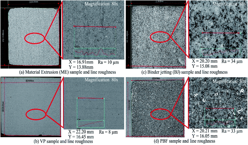 | ||
| Fig. 5 Morphological study of ceramic materials obtained from (a) Material Extrusion (ME); (b) Vat Photo-polymerization (VP); (c) Binder Jetting (BJ); and (d) Powder Bed Fusion (PBF). | ||
The shape and size of pores vary from process to process despite using the AM technique. It is dependent upon the material specifications such as type, particle size, and material synthesis. The spherical particles allow the flowability of the material without obstruction and mechanically entangle with each other during curing process. While the non-spherical particles can cause reduced rate of flowability and increase the surface area and pore density and size.
Table 2 presents the detailed information of pore size and porosity of the various samples obtained by different AM processes and materials. From the given information, the potential of AM processes can be stated by controlling the material properties and the process parameters, the desired pore size and porosity parameters can be obtained and applied for suitable applications. The samples obtained with pore size between 1 μm to 1000 μm can be used for particle filtration, 0.1–10 μm for micro filtration, 0.01–0.5 μm for ultrafiltration; while objects with <0.1 μm are applicable for nano filtration and reverse osmosis. In context, most of the AM processes are suitable for particle and micro filtration applications. Through the design of AM, different porous bed structures can be shaped like sphere, tetrahedral, stella octangula, etc. which can increase the fluid-solid contact efficiency.
3.2 Direct and indirect manufacturing process
The AM processes can also be categorized as direct or indirect type fabrication. The specific meaning of for direct and indirect is stated as following by Zocca et al.:37• Direct manufacturing means, the material is deposited directly as per the desired 3D shape to create the final object and requires no post processing.
• Indirect manufacturing means that, the material deposited above the platform forms a green body and requires additional steps like curing, debinding, sintering process to let the work object achieve its final strengths and properties. The additional steps may vary based on the type of process and the material.
For materials like photopolymers and the VP and ME type AM process, the fabrication type is considered indirect type as the printed objects tend to have scaffold structures that are printed along with the object to support the overhang features of the object. The scaffold structures must be removed after the print is completed. The AM processes like PBF and DED can fabricate the work objects through direct type fabrication. The PBF and DED uses the laser or plasma sources, which can heat the material and fuse the powder particles causing a dense final object. Where as in SL, BJ and MJ processes the binder material that is used to hold the structure particles, requires sintering process to make a dense final object. Debinding and sintering steps are usually required for ceramics and metal materials. The polymer and thermoplastic materials are usually infiltrated with resin,38 copper,39 ceramic or metals40 to obtain additional strength and mechanical properties.
In the next section, different kinds of effect have been demonstrated for the ease of ceramic membrane fabrication by utilizing 3D printing. Thus, as per the Fig. 6, sintering temperature, thermal debinding and infiltration processes were elaborated thoroughly. Fig. 6 indicates the flowchart of 3D printing process for ceramic membrane fabrication.
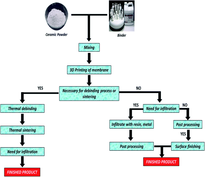 | ||
| Fig. 6 Schematic flowchart of 3D printing process of ceramic membrane fabrication [note: specifically, ceramic material has been considered for production of membrane]. | ||
3.3 Suitable AM methods for ceramic membrane fabrication
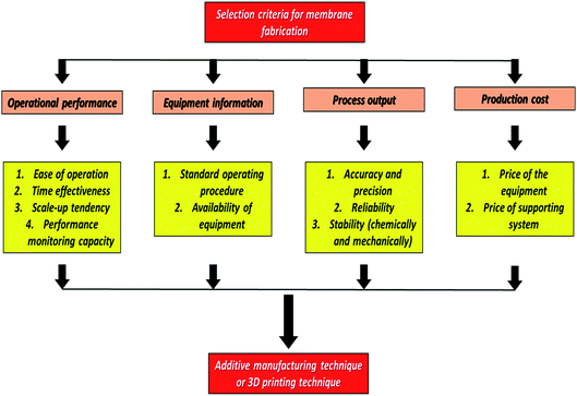
In this section, a three-level hierarchy model is presented, as illustrated in Fig. 8. The selection criteria in the three-level hierarchy are as follows:(a) Goal 1: Goal 1 is the overall goal for ceramic membrane fabrication.
(b) Goal 2: Goal 2 involves the identification of relevant goals, such as the operational performance, equipment information, process output, and production cost.
(c) Goal 3: Goal 3 involves dividing the criteria into subcriteria according to priority rankings and the optimal alternative.
Different AM methods have their advantages and disadvantages, which makes them suitable for specific applications. In this paper, the AM materials and methods available for ceramic membrane fabrication are reviewed. The key parameters of the AM methods are reviewed to select suitable methods for ceramic membrane fabrication. The key parameters selected in the review are presented in Table 4. According to the key parameter values, AM methods are used to fabricate ceramic membranes for various water treatment processes, such as MF, UF, NF, and RO.
| Commercial AM system | AM technology | Materials | Layer resolution (μm) | Material phase | Applications in water treatment |
|---|---|---|---|---|---|
| 3D systems | SLA | Photopolymers | 50 | Resin | Depends on surface chemistry and pore size |
| Carbon 3D | CLIP | Photopolymers | 50 | Resin | Same as above |
| Lithoz | LCM | Alumina, zirconia, silicon nitride | 10–100 | Slurry | Applicable where ceramic based membrane can be utilized |
| 3S | Alumina, zirconia | 50 | Slurry | Same as above | |
| Nanoscribe GmbH | TPP | Photoresists | 0.15 | Resin | To be explored |
| ExOne | Voxeljet | Polymers, ceramics, alloys and composites | 1.0 | Powder | MF, UF, NF, RO, MD, FO |
| 3D systems | Multijet (MJM) | Photopolymers, ceramics, polyamide, binders, solvents | 30 | Powder | MF |
| Stratasys | Polyjet | Photopolymers, ceramics, polyamide, binders, solvents | 50 | Powder mixed with binder/resin | MF |
| Stratasys | FDM | Thermoplastics, porcelain, clay, eutectic metals | 127–330 | Filament | To be explored |
| 3D systems | SLS | Photopolymers, thermoplastics, ceramics, metals | 60–180 | Powder | MF |
| 3D systems | SLM | Metals, alloys, ceramics | 20–100 | Powder | Applicable where ceramic based membrane can be utilized |
4. Advantages and implementations of AM technique for novel ceramic membrane fabrication
Selecting the most appropriate AM technique for any application is difficult. Hence, this section presents the main advantages of AM techniques in comparison with conventional manufacturing techniques. Table 5 summarizes the major advantages of AM techniques that can be useful for the fabrication of novel ceramic membranes for separation and purification technology.| Factors | Description | References |
|---|---|---|
| Speed | • Designing of geometrically complex designs | 54 |
| • 3D printing by using CAD model within few hours | ||
| • Rapid verification | ||
| One step manufacturing process | • Starts with CAD model | 55 |
| • Uploaded to the machine and printed | ||
| Cost effectiveness | • Machine cost: first installation is expensive | 56 |
| • Machine operational cost: consume same amount of electricity as a computer (cheaper) | ||
| • Material cost: depends on various applications | ||
| • Labor cost: almost zero as compared to other conventional techniques | ||
| No wastage of material | • Produces less wastage | 57 |
| • Designs as per the model | ||
| Avoiding risk | • Verification by printing production-ready prototype | 58 |
| • Avoids loss of money and time before mass production | ||
| Freedom of designing | • Printed with more precision and accuracy | 59 |
| • Less chance of faulty design | ||
| • Easy production of complex geometries |
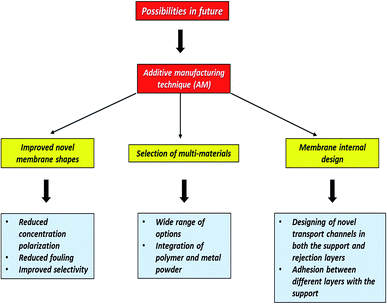
Ceramic membrane fabrication through conventional techniques involves many challenges, including the alignment of transport channels in both the support and separating layers and adhesion between different phases and with the support. Therefore, AM plays a prominent role in the field of ceramic membrane fabrication. It provides a unique pathway to accurately print ceramic membranes as multimaterial single monolithic pieces with a complex configuration. This pathway can prevent AM drawbacks related to accuracy and resolution. Moreover, microporous materials can be combined with printing materials. As a result, the final product has achievable micrometer-size properties, with microporosity of its porous components. AM techniques can be used to fabricate a tailored scaffold-like membrane made of porous nanomaterials and polymers. Thus, novel membrane shapes with reduced concentration polarization and fouling and improved selectivity can be designed using AM techniques. AM approaches must be suitably executed so that a product can be printed accurately. Fig. 9 illustrates how AM techniques can be used for fabricating improvised ceramic membranes with enhanced selectivity and productivity.
AM techniques can be easily implemented for ceramic membrane fabrication. Certain parameters can be easily optimized for AM techniques during the ceramic membrane fabrication process. These parameters are as follows:
(1) Membrane configuration: Membranes are currently restricted to mainly flat sheets and tubular/hollow fiber configurations due to the limitations of current manufacturing processes. However, AM techniques can be effectively utilized to eliminate this limitation.
(2) Surface shape: Novel membranes with complex pore structures and surface shapes improve micromixing and shear flow across the membrane surface. These membranes can be utilized to reduce energy and downtime associated with cleaning pore blockages and membrane fouling.
(3) Porous structure: AM techniques allow superior control over the membrane structure. AM techniques can easily adjust the pore size and pore size distribution through CAD for optimizing water flux and separation efficiency.
(4) Membrane thickness: The membrane thickness is considered as an important parameter in various systems. AM techniques offer superior control over the membrane thickness, which can be optimized using a computer program. AM can also provide researchers with unprecedented control over the membrane architecture.
(5) Environmental friendliness: AM techniques are associated with decreased energy consumption and solvent use during the membrane fabrication process. Thus, AM is an environmentally friendly method for membrane fabrication.
5. Research challenges and future perspectives
Despite the numerous advantages of AM techniques, these techniques have few disadvantages that may influence ceramic membrane fabrication. Current research challenges must be considered for optimizing the parameters and factors in the future. The current research challenges related to using the 3D printing technique for ceramic membrane fabrication are as follows:(a) The resolution of AM techniques must be improved to fabricate ceramic membranes with increased precision and accuracy.
(b) The fabrication of ceramic membranes through AM techniques is currently in the infancy stage. Therefore, updated research and development are required to increase the scalability of the techniques.
(c) The cost of AM techniques should be made competitive with that of other conventional processes, such as phase inversion.
The advantages and applications of AM techniques may revolutionize the design of innovative ceramic membranes if the inherent drawbacks of 3D printing for membrane fabrication can be overcome (Table 1). The most suitable areas in which the AM technique can be applied are the separation and purification fields as well as the medical field.16,59,60 Compared with conventional ceramic membrane fabrication techniques, AM techniques have unique features, which are listed as follows:
(a) Wide range of applications: AM techniques can be used to generate a structure with almost any complex geometrical shape. AM techniques can also be applied in different fields, including manufacturing, art, medicine, and engineering. However, AM is a relatively new technique for ceramic membrane fabrication engineering. Through AM, novel and unique ceramic membranes and membrane modules can be designed, which may enhance mass transfer.
(b) Designing innovative and accurate membranes: 3D printing techniques can be used to fabricate geometrically novel ceramic membranes of different structures, shapes, and types. Ceramic membranes can be designed and controlled more accurately with 3D printing techniques than with recent conventional membrane fabrication methods. Furthermore, 3D printing techniques can be utilized to fabricate ceramic membranes with precisely designed pores and surface shapes, which can improve mass transfer and shear flow across the membrane surface and simultaneously reduce membrane fouling. The 3D printing technique can be used to control the membrane thickness, which is not possible in other conventional methodologies. In general, traditional techniques cannot be used to control these properties independently with high resolution or precision.
(c) Time effectiveness: One of the major advantages of 3D printing technology is the speed at which membranes can be created. Geometrically complex designs can be created using CAD models and can be printed in a few minutes to few hours.
6. Conclusions
The current trend of research and development of 3D printed ceramic membranes has attracted a lot of attention from researchers due to high versatility. The production of ceramic membranes by AM technique comes out as one of the emerging techniques in ceramic membrane technology in the areas of water purification application. The AM technique has the ability to generate ceramic membranes of different structures, various types and geometrically complex designs, that improves the mass transfer as well as shear flow across the membrane.This review article analyses the recent AM technology and how it is useful for ceramic membrane-based water treatment. Overall it can be concluded that AM technique cannot be provided at low cost as the basic set-up cost is bit expensive compared to all the other conventional techniques available. 3D printing technique is a high-cost protocol to produce ceramic membranes which has become a prohibitive factor.
6.1 Need of high-resolution AM technique
It is the right time to have an ideal 3D printing technique for producing membranes with high precision, high resolution, and high printing speed ability.6.2 Wide range of materials for membrane fabrication
The printing materials are limited as well as restricted to specific 3D printing technologies. In other words, development of the printing materials as well as 3D printing technique need to be expanded as both are equally important to produce membrane for separation and purification technology.6.3 Cost effectiveness
As per the recent report, it is believed that 15 per cent of energy is utilized worldwide for separation and purification of industrial products such as chemicals, reusable water and gases. However, membrane processes offer lower operational cost, lower energy consumption and more sustainable molecular separations which can be utilized for a wide range of applications including gas and liquid separations. Therefore, it is important to decrease the carbon footprint and costs within industry by using this technique in future.This comprehensive review article demonstrates a clear picture of 3D printing technique (or so-called AM techniques) could be utilized in membrane engineering field. The applications of AM technique in membrane technologies may expect more research and development in near future.
Conflicts of interest
There are no conflicts to declare.Acknowledgements
(1) This work was financially supported by the “Additive Manufacturing Center for Mass Customization Production” from The Featured Areas Research Center Program within the framework of the Higher Education Sprout Project by the Ministry of Education (MOE) in Taiwan. (2) Ministry of Science and Technology (MOST), Taiwan, Republic of China (ROC) under grant number 107-2221-E-027-001-MY3.References
- R. Bogue, Assemb. Autom., 2013, 33, 307 CrossRef
.
- P. Dudek, Arch. Metall. Mater., 2013, 58, 1415 CAS
.
- S. C. Ligon, R. Liska, J. r. Stampfl, M. Gurr and R. Mülhaupt, Chem. Rev., 2017, 117, 10212 CrossRef CAS PubMed
.
- J. Deckers, J. Vleugels and J.-P. Kruth, J. Ceram. Sci. Technol., 2014, 5, 245 Search PubMed
.
- W. E. Frazier, J. Mater. Eng. Perform., 2014, 23, 1917 CrossRef CAS
.
- J. Lee, Three-dimensional printer, ceramic article and method of manufacture, US Pat., US 8,568,649 B1, 2018
.
-
(a) J. Wang, A. Goyanes, S. Gaisford and A. W. Basit, Int. J. Pharm., 2016, 503, 207 CrossRef CAS PubMed
; (b) F. Fina, A. Goyanes, S. Gaisford and A. W. Basit, Int. J. Pharm., 2017, 529, 285 CrossRef CAS PubMed
; (c) J. Skowyra, K. Pietrzak and M. A. Alhnan, Eur. J. Pharm. Sci., 2015, 68, 11 CrossRef CAS PubMed
.
- W. S. Tan, S. R. Suwarno, J. An, C. K. Chua, A. G. Fane and T. H. Chong, J. Membr. Sci., 2017, 537, 283 CrossRef CAS
.
- C. Fee, S. Nawada and S. Dimartino, J. Chromatogr. A, 2014, 1333, 18 CrossRef CAS PubMed
.
- A. Siddiqui, N. Farhat, S. S. Bucs, R. V. Linares, C. Picioreanu, J. C. Kruithof, M. C. van Loosdrecht, J. Kidwell and J. S. Vrouwenvelder, Water Res., 2016, 91, 55 CrossRef CAS PubMed
.
- B. S. Lalia, V. Kochkodan, R. Hashaikeh and N. Hilal, Desalination, 2013, 326, 77 CrossRef CAS
.
- R. W. Baker and U. b. Staff, Kirk-Othmer Encyclopedia of Chemical Technology, 2000 Search PubMed
.
- Z. Cui, N. T. Hassankiadeh, S. Y. Lee, J. M. Lee, K. T. Woo, A. Sanguineti, V. Arcella, Y. M. Lee and E. Drioli, J. Membr. Sci., 2013, 444, 223 CrossRef CAS
.
- J. Kong and K. Li, J. Appl. Polym. Sci., 2001, 81, 1643 CrossRef CAS
.
-
(a) S. S. Ray, S.-S. Chen, C.-W. Li, N. C. Nguyen and H. T. Nguyen, RSC Adv., 2016, 6, 85495 RSC
; (b) Z.-M. Huang, Y.-Z. Zhang, M. Kotaki and S. Ramakrishna, Compos. Sci. Technol., 2003, 63, 2223 CrossRef CAS
.
- Z.-X. Low, Y. T. Chua, B. M. Ray, D. Mattia, I. S. Metcalfe and D. A. Patterson, J. Membr. Sci., 2017, 523, 596 CrossRef CAS
.
-
(a) A. M. Stephan and D. Teeters, Electrochim. Acta, 2003, 48, 2143 CrossRef
; (b) J. Mulder, Basic principles of membrane technology, Springer Science & Business Media, 2012 Search PubMed
; (c) S. S. Ray, M. Gandhi, S.-S. Chen, H.-M. Chang, C. T. N. Dan and H. Q. Le, Environ. Sci.: Water Res. Technol., 2018, 4, 1612–1623 RSC
; (d) S. S. Ray, M. Gandhi, S.-S. Chen, H.-M. Chang, C. T. N. Dan and H. Q. Le, Environ. Sci.: Water Res. Technol., 2018, 4, 1612 RSC
; (e) S. S. Ray, S.-S. Chen, H.-M. Chang, C. N. D. Thanh, H. Q. Le and N. C. Nguyen, RSC Adv., 2018, 8, 9640 RSC
.
-
(a) N. Bhardwaj and S. C. Kundu, Biotechnol. Adv., 2010, 28, 325 CrossRef CAS PubMed
; (b) S. S. Ray, S.-S. Chen, H.-T. Hsu, D.-T. Cao, H.-T. Nguyen and N. C. Nguyen, Sep. Purif. Technol., 2017, 186, 352–365 CrossRef CAS
.
-
(a) S. Knowlton, B. Yenilmez and S. Tasoglu, Trends Biotechnol., 2016, 34, 685 CrossRef CAS
; (b) A. A. Yazdi, A. Popma, W. Wong, T. Nguyen, Y. Pan and J. Xu, Microfluid. Nanofluidics, 2016, 20, 50 CrossRef
.
- N. Guo and M. C. Leu, Front. Mech. Eng., 2013, 8, 215 CrossRef
.
- K. V. Wong and A. Hernandez, ISRN Mech. Eng., 2012, 2012, 1–10 CrossRef
.
- A. C. C.-o. Concrete and C. Aggregates, Standard specification for coal fly ash and raw or calcined natural pozzolan for use in concrete, ASTM International, 2013 Search PubMed
.
- L. Elomaa, A. Kokkari, T. Närhi and J. V. Seppälä, Compos. Sci. Technol., 2013, 74, 99 CrossRef CAS
.
- C. E. Corcione, A. Greco, F. Montagna, A. Licciulli and A. Maffezzoli, J. Mater. Sci., 2005, 40, 4899 CrossRef CAS
.
- H. Wu, W. Liu, R. Huang, R. He, M. Huang, D. An, H. Li, Q. Jiang, Z. Tian and X. Ji, Mater. Chem. Phys., 2018, 209, 31 CrossRef CAS
.
- J. L. Li, Y. L. Cai, Y. L. Guo, J. Y. H. Fuh, J. Sun, G. S. Hong, R. N. Lam, Y. S. Wong, W. Wang and B. Y. Tay, J. Biomed. Mater. Res., Part B, 2014, 102, 651 CrossRef PubMed
.
- T. Wang and B. Derby, J. Am. Ceram. Soc., 2005, 88, 2053 CrossRef CAS
.
- S. Tarafder, V. K. Balla, N. M. Davies, A. Bandyopadhyay and S. Bose, J. Tissue Eng. Regenerat. Med., 2013, 7, 631 CrossRef CAS PubMed
.
- J. Suwanprateeb, F. Thammarakcharoen, V. Wongsuvan and W. Chokevivat, J. Porous Mater., 2012, 19, 623 CrossRef CAS
.
- A. Ghazanfari, W. Li, M. C. Leu and G. E. Hilmas, Addit. Manuf., 2017, 15, 102 CrossRef
.
- M. Too, K. Leong, C. Chua, Z. Du, S. Yang, C. Cheah and S. Ho, Int. J. Adv. Manuf. Technol., 2002, 19, 217 CrossRef
.
- S. J. Hollister, Nat. Mater., 2005, 4, 518 CrossRef CAS PubMed
.
- K. Shahzad, J. Deckers, J.-P. Kruth and J. Vleugels, J. Mater. Process. Technol., 2013, 213, 1484 CrossRef CAS
.
- Y. Zhang, X. He, S. Du and J. Zhang, Int. J. Adv. Manuf. Technol., 2001, 17, 531 CrossRef
.
- H. Windsheimer, N. Travitzky, A. Hofenauer and P. Greil, Adv. Mater., 2007, 19, 4515 CrossRef CAS
.
- A. Bandyopadhyay, B. V. Krishna, W. Xue and S. Bose, J. Mater. Sci.: Mater. Med., 2009, 20, 29 CrossRef
.
- A. Zocca, P. Colombo, C. M. Gomes and J. Günster, J. Am. Ceram. Soc., 2015, 98, 1983 CrossRef CAS
.
- M. P. Paranthaman, C. S. Shafer, A. M. Elliott, D. H. Siddel, M. A. McGuire, R. M. Springfield, J. Martin, R. Fredette and J. Ormerod, JOM, 2016, 68, 1978 CrossRef CAS
.
- R. Melcher, S. Martins, N. Travitzky and P. Greil, Mater. Lett., 2006, 60, 572 CrossRef CAS
.
- A. Levy, A. Miriyev, A. Elliott, S. S. Babu and N. Frage, Mater. Des., 2017, 118, 198 CrossRef CAS
.
- Z. Cui, Encyclopedia of Membranes, 2015, vol. 1 Search PubMed
.
-
(a) M. Huang, T. Liu, Y. Deng, H. Geng, Y. Shen, Y. Lin and C.-W. Nan, Solid State Ionics, 2011, 204, 41 CrossRef
; (b) G. Muralithran and S. Ramesh, Ceram. Int., 2000, 26, 221 CrossRef CAS
.
-
(a) M. Trunec and J. Cihlář, J. Eur. Ceram. Soc., 1997, 17, 203 CrossRef CAS
; (b) E. Thian, N. Loh, K. Khor and S. Tor, Adv. Powder Technol., 2001, 12, 361 CrossRef CAS
.
-
(a) X. Li, L. Zhang, X. Yin, L. Feng and Q. Li, Scr. Mater., 2010, 63, 657 CrossRef CAS
; (b) B. Sun, T. Fan, D. Zhang and T. Okabe, Carbon, 2004, 42, 177 CrossRef CAS
; (c) E. O. Garzón, J. L. Alves and R. J. Neto, in Materials Design and Applications, Springer, 2017 Search PubMed
.
-
(a) N. A. Chartrain, C. B. Williams and A. R. Whittington, Acta Biomater., 2018, 74, 90–111 CrossRef CAS
; (b) S. Nayar, S. Bhuminathan and W. M. Bhat, J. Pharm. BioAllied Sci., 2015, 7, S216 Search PubMed
; (c) J.-C. Wang and H. Dommati, Int. J. Adv. Manuf. Technol., 2018, 98, 1537 CrossRef
.
- Y. Tang, Y. Zhou, T. Hoff, M. Garon and Y. Zhao, Mater. Sci. Technol., 2016, 32, 648 CrossRef CAS
.
-
(a) B. K. Gu, D. J. Choi, S. J. Park, M. S. Kim, C. M. Kang and C.-H. Kim, Biomater. Res., 2016, 20, 12 CrossRef PubMed
; (b) G. Manogharan, M. Kioko and C. Linkous, JOM, 2015, 67, 660 CrossRef CAS
; (c) D.-A. Türk, L. Triebe and M. Meboldt, Procedia CIRP, 2016, 50, 402 CrossRef
.
-
(a) J. Ebert, E. Özkol, A. Zeichner, K. Uibel, Ö. Weiss, U. Koops, R. Telle and H. Fischer, J. Dent. Res., 2009, 88, 673 CrossRef CAS PubMed
; (b) J. Norman, R. D. Madurawe, C. M. Moore, M. A. Khan and A. Khairuzzaman, Adv. Drug Deliv. Rev., 2017, 108, 39 CrossRef CAS PubMed
.
- A. R. Torrado, C. M. Shemelya, J. D. English, Y. Lin, R. B. Wicker and D. A. Roberson, Addit. Manuf., 2015, 6, 16 CrossRef CAS
.
- M. Mani, B. M. Lane, M. A. Donmez, S. C. Feng and S. P. Moylan, Int. J. Prod. Res., 2017, 55, 1400 CrossRef
.
- S. L. Sing, W. Y. Yeong, F. E. Wiria, B. Y. Tay, Z. Zhao, L. Zhao, Z. Tian and S. Yang, Rapid Prototyp. J., 2017, 23, 611 CrossRef
.
- X. Yin, N. Travitzky and P. Greil, Int. J. Appl. Ceram. Technol., 2007, 4, 184 CrossRef CAS
.
- D. Klosterman, R. Chartoff, G. Graves, N. Osborne and B. Priore, Composites, Part A, 1998, 29, 1165 CrossRef
.
- B. Mueller, Assemb. Autom., 2012, 32 DOI:10.1108/aa.2012.03332baa.010
.
- C. L. Ventola, Pharm. Therapeut., 2014, 39, 704 Search PubMed
.
- B. Berman, Bus. Horiz., 2012, 55, 155 CrossRef
.
- X. Wang, M. Jiang, Z. Zhou, J. Gou and D. Hui, Composites, Part B, 2017, 110, 442 CrossRef CAS
.
- A. Roth and T. Singer, Adv. Drug Deliv. Rev., 2014, 69, 179 CrossRef PubMed
.
- J.-Y. Lee, W. S. Tan, J. An, C. K. Chua, C. Y. Tang, A. G. Fane and T. H. Chong, J. Membr. Sci., 2016, 499, 480 CrossRef CAS
.
- J.-Y. Lee, J. An and C. K. Chua, Appl. Mater. Today, 2017, 7, 120 CrossRef
.
Footnote |
| † Both authors contributed equally to this manuscript. |
| This journal is © The Royal Society of Chemistry 2019 |

